Page is loading ...

OWNER'S MANUAL
H-6700 SERIES
DIGITAL IR LANGUAGE DISTRIBUTION SYSTEM
Version: REV1.0 (2015)

1
[Table of Contents]
Important Safety Instructions---------------------------------------------------------------------------------------------------3
1. Overview-------------------------------------------------------------------------------------------------------------------5
1.1 Digital Infrared transmitter --------------------------------------------------------------------------------------------6
1.1.1 Picture of the actual object --------------------------------------------------------------------------------------------6
1.1.2 Features of digital infrared transmitter------------------------------------------------------------------------------6
1.1.3 Schematic diagram of digital infrared transmitter----------------------------------------------------------------6
1.1.4 Parameter of infrared transmitter------------------------------------------------------------------------------------7
1.2 Digital infrared radiator-------------------------------------------------------------------------------------------------8
1.2.1 Picture of the actual object --------------------------------------------------------------------------------------------8
1.2.2 Features of infrared radiator ------------------------------------------------------------------------------------------8
1.2.3 Schematic diagram of infrared radiator ----------------------------------------------------------------------------8
1.2.4 Parameter of infrared radiator ----------------------------------------------------------------------------------------9
1.3 Digital interpreter console --------------------------------------------------------------------------------------------9
1.3.1 Picture of the actual object --------------------------------------------------------------------------------------------9
1.3.2 Features of interpreter console --------------------------------------------------------------------------------------9
1.3.3 Schematic diagram of interpreter console -----------------------------------------------------------------------10
1.3.4 Parameter of interpreter console ----------------------------------------------------------------------------------10
1.4 Digital Infrared receiver ----------------------------------------------------------------------------------------------11
1.4.1 Picture of the actual object ------------------------------------------------------------------------------------------11
1.4.2 Features of digital Infrared receiver -------------------------------------------------------------------------------11
1.4.3 Schematic diagram of digital Infrared receiver -----------------------------------------------------------------11
1.4.4 Parameter of digital Infrared receiver -----------------------------------------------------------------------------12
1.5 Charging unit------------------------------------------------------------------------------------------------------------12
1.5.1 Picture of the actual object ------------------------------------------------------------------------------------------12
1.5.2 Features of charging unit- -------------------------------------------------------------------------------------------12
1.5.3 Schematic diagram of charging unit ------------------------------------------------------------------------------12
1.5.4 Parameter of charging unit ------------------------------------------------------------------------------------------13
1.6 Repeater unit-----------------------------------------------------------------------------------------------------------13
1.6.1 Picture of the actual object ------------------------------------------------------------------------------------------13
1.6.2 Features of repeater unit---------------------------------------------------------------------------------------------13
1.6.3 Parameter of repeater unit-------------------------------------------------------------------------------------------13
2. System installation-----------------------------------------------------------------------------------------------------14
2.1 System connection diagram-----------------------------------------------------------------------------------------14
2.2 Warning------------------------------------------------------------------------------------------------------------------15
2.2.1 CAUTION on handling of the receiver unit---------------------------------------------------------------------15
2.2.2 CAUTION on installation radiator----------------------------------------------------------------------------------15
2.2.3 CAUTION on battery charger handling---------------------------------------------------------------------------15
2.3 Planning------------------------------------------------------------------------------------------------------------------16
2.3.1 Aspects of infrared distribution systems--------------------------------------------------------------------------16
2.3.2 Directional sensitivity of the receiver------------------------------------------------------------------------------16
2.3.3 The footprint of the radiator------------------------------------------------------------------------------------------17
2.3.4 Position the radiator---------------------------------------------------------------------------------------------------18
2.3.5 Cabling--------------------------------------------------------------------------------------------------------------------20
2.3.6 Set the delay switches------------------------------------------------------------------------------------------------21

2
2.3.7 Determine the radiator delay switch positions-----------------------------------------------------------------21
2.4 System configuration-------------------------------------------------------------------------------------------------22
2.5 Transmitter installation and connection--------------------------------------------------------------------------22
2.5.1 Transmitter installation------------------------------------------------------------------------------------------------22
2.5.2 TNC connector installation method--------------------------------------------------------------------------------22
2.5.3 Connect radiators------------------------------------------------------------------------------------------------------23
2.5.4 Connect interpreter console-----------------------------------------------------------------------------------------23
2.5.5 Connect other external audio sources----------------------------------------------------------------------------24
2.6 Installation of IR radiator---------------------------------------------------------------------------------------------24
2.6.1 Installation of radiator with bracket---------------------------------------------------------------------------------24
2.6.2 Caution item-------------------------------------------------------------------------------------------------------------25
2.7 Installation of interpreter console----------------------------------------------------------------------------------25
2.7.1 Mounting and dismounting the microphone---------------------------------------------------------------------25
2.7.2 Connection headset to interpreter console----------------------------------------------------------------------25
2.8 Installation of infrared receiver-------------------------------------------------------------------------------------26
2.8.1 Battery install------------------------------------------------------------------------------------------------------------26
2.8.2 Connect earphone to receiver---------------------------------------------------------------------------------------26
2.9 System setting----------------------------------------------------------------------------------------------------------26
2.9.1 System mode------------------------------------------------------------------------------------------------------------26
2.9.2 Interpreter setting------------------------------------------------------------------------------------------------------28
3. System operation and function-------------------------------------------------------------------------------------30
3.1 Digital infrared transmitter-------------------------------------------------------------------------------------------30
3.3.1 On/Off the transmitter---- --------------------------------------------------------------------------------------------30
3.3.2 Transmitter LCD--------------------------------------------------------------------------------------------------------30
3.3.3 Transmitter LED--------------------------------------------------------------------------------------------------------30
3.3.4 Mini IR-radiator---------------------------------------------------------------------------------------------------------30
3.2 Interpreter Console----------------------------------------------------------------------------------------------------30
3.3.1 On/Off the interpreter---- ---------------------------------------------------------------------------------------------30
3.3.2 Monitor (Input channel) --- -------------------------------------------------------------------------------------------31
3.3.3 Interpreter microphone on/off---------------------------------------------------------------------------------------31
3.3.4 Mute function------------------------------------------------------------------------------------------------------------31
3.3.5 Slow function------------------------------------------------------------------------------------------------------------31
3.3 Digital infrared receiver-----------------------------------------------------------------------------------------------32
3.3.1 On/Off the receiver---- ------------------------------------------------------------------------------------------------32
3.3.2 Channel/volume debug-----------------------------------------------------------------------------------------------32
3.3.3 Battery capacity warning---------------------------------------------------------------------------------------------32
3.3.4 Automatically off--------------------------------------------------------------------------------------------------------32
3.4 Charging unit------------------------------------------------------------------------------------------------------------33
4. Troubleshooting-------------------------------------------------------------------------------------------------------34

3
Important Safety Instructions
1. Please read this safety instruction carefully before installing and using the apparatus.
2. Please keep these safety instructions for future reference.
3. Please strictly heed all warnings in the user’s guide.
4. Please follow all the operation instructions in the user’s guide.
5. To prevent from any hazard, do not use this apparatus near water.
6. Equipment cleaning: Make sure to turn off the power supply and disconnect the units before cleaning.
Clean only with a dry soft cloth.
7. Do not block any ventilation openings. Install in accordance with the manufacture’s instructions.
8. Do not install near any heat sources such as radiators. Heat registers, stoves or other apparatus
(including amplifiers) that produce heat.
9. Grounding: 3-wire grounding plug, and do not defeat the safety purpose of this plug. A grounding type
plug has two blades and a third grounding prong, the third prong are provided for your safety. If the
provided plug does not fit into your outlet, consult an electrician for replacement of the obsolete outlet.
10. Protect the power cord from being walked on or pinched particularly at plugs, convenience
receptacles, and the point where they exit from the apparatus.
11. To prevent from any hazard, only use attachments/accessories specified by the manufacturer.
12. Use only with the cart, stand, tripod, bracket, or table specified by the manufacturer, or sold with the
apparatus. When a cart is used, use caution when moving the cart/apparatus combination to avoid
injury from tip-over.
13. Unplug this apparatus during lighting storms or when unused fro long periods of time.
14. Refer all servicing to nearest qualified service centre. Servicing is required when the apparatus has
been damaged in any way, such as power-supply cord or plug is damaged, liquid has been spilled or
objects have fallen into the apparatus, the apparatus has been exposed to rain or moisture, does not
operate normally, or has been dropped.
15. Do not place the equipment on any uneven or unstable stand; original product package or appropriate
package should be used to avoid damage caused by strong impacts during transportation.
16. The quantity if connected IR radiators in one system should not exceed prescribed quantity. For
service, please contact the nearest service center.
17. All products are guaranteed for 1 year excluding the following cases:
a. all damage or malfunction caused by human negligence;
b. Damage or malfunction caused by improper operating by operator;
c. Parts damage or loss caused by disassembling the product by non-authorized personnel.
18. Use only specified connection cable to connect the system equipment.

4
This label appears on the rear of the unit duce to space limitations

5
1. Overview
The digital IR language distribution system is a system for wireless distribution of audio signals via
infrared radiation. It can be used in a simultaneous interpretation system for international conferences
where multiple languages are used. To enable all participants to understand the discussion, interpreters
simultaneously translate the speaker’s language as required. These interpretations are distributed
throughout the conference venue, and delegates select the language of their choice and listen to it
through headphones. The system can also be used for music distribution.
This digital language distribution system comprises one or more of the following:
Infrared transmitter
The transmitter is the core of the system. Four types are available:
- Inputs for 4 audio channels
- Inputs for 8 audio channels
- Inputs for 12 audio channels
- Inputs for 16 audio channels
Infrared radiator
The radiators can be mounted on walls, ceilings or floor stands.
- The raidator support up to 32 channels audio transmission
Infrared receivers
Five multi-channel infrared receivers are available:
- 4 audio channels
- 8 audio channels
- 12 audio channels
- 16 audio channels
- 32 audio channels
The receivers can operate with rechargeable NiMH batteries or with disposable batteries. Charging
circuitry is incorporated in the receiver.
Interpreter consoles
Five Interpreter consoles are available:
- 4 audio channels
- 8 audio channels
- 12 audio channels
- 16 audio channels
- 32 audio channels
Charging equipment
- The charging unit is for charging and storing 24 infrared receivers.
Repeater
-The repeater for boost the transmission signals of interpreter consoles

6
1.1 Digital Infrared transmitter H-6700M
1.1.1 Picture of the actual object
1.1.2 Features of digital infrared transmitter
a. Fully digital wireless transmission technology. System conforms to IEC61603, part 7.
b. 2-8MHz frequency band eliminates disturbance from all types of lighting systems.
c. The system provides multi-channel 4/8/12/16 for option
d. High security, prevent external interference.
e. Elegant configuration in accordance to ergonomics.
f. 160x32 dot matrix LCD display system information
g. Installation: 19-inch frame
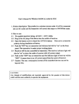
1.1.3 Schematic diagram of digital Infrared transmitter
1) Power on/off switch: Power switch (Press I to turn on the power, power indicator is lighting, press O to
turn off the power)
2) Menu display LCD: The LCD-display gives information about the transmitter status,. It also use as an
interactive display for configuring the system)
3) Transmitter communication LED: This LED is used for display the system communication status, if
the communication properly, the LED will flashing rhythmically, if the LED stop flashing during
working, the transmitter may has problem.

7
4) Menu button: To operate the configuration system inputs/languages/safety settings, etc.
5) Normal button: To setting the normal working status—interpretation, the corresponding LED is green
one.
6) Auxiliary button: To setting the auxiliary working status—music, the corresponding LED is orange
one.
7) Alarm button: To setting the alarm working status—emergency time, the corresponding LED is red
one.
8) Management card LED: the LED will lighting when management card correctly insert.
9) Management card interface: User must insert the correct card during setting
10) Mini IR-radiator: Four IREDs, transmitting the same infrared signal as the radiator output. This can be
used for monitoring purposes.
11) Interpreter connector: Use for connection interpreter consoles
12) Conference connector: Use for connect compatible conference system
13) RS232 interface: Use for connect computer.
14) Auxiliary audio inputs: Female RCA connector for external audio inputs to connect auxiliary audio
signals such as music, floor language or emergency audio signal
15) Emergency audio inputs: Female RCA connector for emergency audio signal, when this function
available, system will distribute the emergency audio signal to all output channels and overriding all
other audio inputs.
16) HF signal output: Four HF TNC connectors, used to connect the radiators. Up to 30 Radiators can be
loop-through connected to each output.
17) Audio signal output: 4/8/12/16 audio connectors to connect other audio equipments. The number of
connectors depends on the transmitter type
18) Audio signal input: 4/8/12/16 audio connectors to connect external unbalanced audio input signals.
The number of connectors depends on the transmitter type.
19) Power supply: The transmitter has automatic voltage selection. A power cable is provided.
1.1.4 Parameter of infrared transmitter
Items Parameter
Modulation frequency
Carriers 0 to5: 2 to 6 MHz, according to IEC 61603
part 7, Carriers 6 and 7: up to 8MHz
Protocol and modulation DQPSK, according to IEC technique 61603 part 7
Audio frequency response 20Hz-10kHz (-3dB) at standard quality
Total harmonic distortion at 1 kHz <0.05%
Crosstalk attenuation at 1 kHz >80dB
Dynamic range >80dB
Weighted signal-to noise ratio >80dB(A)
Power consumption Operating:100W; Standby: 25W
Asymmetrical audio inputs +3 dBV nominal, +6dBV maximum(±6dB)
HF output 1 Vpp, 6VDC, 50Ohm
Interpreter console connector interface 12P-DIN

8
Audio input RCA x16
Items Parameter
Audio output RCA x16
HF output connector interface TNC x 4
Operating temperature range 0-40 degree
Power supply AC110V-200V ~ 50Hz-60Hz
Dimensions 485×355×90mm
Mounting 19” rack mounting
N.W 8kg
1.2 Digital Infrared radiator H-6700S
1.2.1 Picture of the actual object
1.2.2 Features of digital infrared transmitter
a. Fully digital wireless transmission technology. System conforms to IEC61603, part 7
b. Radiates & distributes up to 32 channels of digital audio signal
c. Digitized audio ensures very high audio quality
d. Powerful compression techniques enable efficient, low-loss transmission.
e. Mounted on ceiling, wall, floor stand or optional tripod
f. Easily daisy-chained together to expand coverage
g. Angle of half intensity: ±22°
1.2.3 Schematic diagram of digital infrared radiator
1) Infrared Leds and IR lens.

9
2) Delay compensation switches: 8-position switches to compensate for differences in cable lengths to
the radiators.
3-4) IR signal input/output: 2 HF TNC connectors for connecting the transmitter and radiator. Input
connector for connecting transmitter directly or the output connector from previous radiator. Output
connector for connecting input connector of next radiator.
5) Power input: Male power plug connector. The radiators have automatic voltage selection.
6) Radiator power on/off switch
7) Bracket hole: Tapped hole to mount the suspension bracket.
1.2.4 Parameter of digital Infrared radiator
Items Parameter
HF input Nominal 1 Vpp, minimum 10mVpp
Angle of half intensity ±22°
Total optical peak intensity 24 W/sr
Power consumption Operating: 30W; Standby:25 W
Transmission distance <30 meters/16 CH
Number of IREDs 312
Power supply AC110V-220V ~ 50Hz-60Hz
Dimensions 445×235×113mm
Operating temperature range 0-40 degree
Mounting Standard: Bracket, Option: tripod
N.W 4.2kg
1.3 Digital interpreter console H-6700Y
1.3.1 Picture of the actual object
1.3.2 Features of interpreter console
a. Digital audio processing and transmitting technology.
b. Up to 32 Channel audio signals transmitted on a dedicated 12P-DIN cable.
c. Interpreter consoles powered by the transmitter.
d. Voice adjustable and with prevention on feedback
e. Ensure that every channel is correspondent to the RELAY function respectively.
f. Delegates speak too fast; give a request for slow the speed.

10
g. Automatic numbering on system units
h. Prevention on interpreter's cough
i. LCD can display input and output channel
1.3.3 Schematic diagram of interpreter console
1) Microphone red indicator to show mic state (on/off)
2) Unidirectional electret MIC
3) Microphone TFT display to show interpreter console’s status
4-5) Interpreter input/loop-through (output): two 12P-DIN connectors for connecting the interpreter
console to the transmitter and for loop-through connection to other interpreter consoles.
6) Earphone jack (ø 3.5mm)
7) Menu key
8) Slow key (SLOW): When the delegate is speaking too fast, press this button (microphone of the
interpreter unit must be active) to remind him/her to slow down)
9) Microphone on/off switch (Micro): Press this button to turn on the microphone and the red indicating
light will be activated, press this button again to turn off the microphone.
10) Microphone mute key (Mute): Push and hold the “Mute” button to temporarily disable the microphone.
Release this button on voice recovery.
11) Volume control and interpreter’s function set knob
12) Built-in Hi-Fi loudspeaker
1.3.4 Parameter of digital Infrared radiator
Items Parameter
Frequency response 50Hz – 20kHz
Sensitivity -42 ± 2dB
Interpreter connector interface 12P-DIN
Length of gooseneck 410mm
Dimensions 300×150×70mm
Operating temperature range 0-40 degree
N.W 1.7kg

11
1.4 Digital infrared receiver H-6700D
1.4.1 Picture of the actual object
1.4.2 Features of digital infrared receiver
a. Fully digital wireless transmission technology. Receiver conforms to IEC61603, part 7
b. Pocket size wireless handheld unit
c. Accommodates up to 32 different languages
d. Channel selector and headphone connector
e. Power on/off switch and volume level control
f. Powered by (2 x AA) rechargeable batteries
g. No power used when headphone is disconnected
h. Aluminum carrying cases provided for receivers
i. 2-digit LCD display with battery and reception status indication
1.4.3 Schematic diagram of digital infrared receiver
1) LCD display: A two digit display showing the selected channel. An antenna symbol is visible when the
receiver picks up an infrared signal of adequate quality. A battery symbol is visible when the batteries
are almost empty.
2-3) Channel selector: An up/down switch to select an audio channel. The channel number is shown on
the LCD display
4) On/Off button: When headphone is connected, the receiver switches to stand-by state. Pressing the
On/Off button switches the receiver from stand-by to on. To switch back to stand-by, press and hold
the button approx. 2 seconds. When the headphone is removed, the receiver switches automatically
to the off-state.
5) Charging contacts: Used in combination with the charging equipment to recharge the batteries
6) Headphone connector: A 3.5mm (0.14 inch) stereo jack output socket for the headphone.
7) IR lens: To receive infrared signals from IR radiators.
8) Volume control: A slider to adjust the volume +/-

12
1.4.4 Parameter of digital Infrared receiver
Items Parameter
Receiving sensitivity -101dBM
Angle of half sensitivity ± 50°
Headphone output level at 2.4V 450 mVrms (Speech at maximum volume, 32 ohm
headphone)
Headphone output frequency range 20 Hz to 10 kHz
Headphone output impedance 32 ohm
Max. signal-to-noise ratio 78 dB(A)
Supply voltage 1.8 to 3.6 V, nominal 2.4 V
Power consumption at 2.4V (battery voltage) 60 mA (speech at maximum volume, 32 ohm
headphone)
Power consumption (standby) 60 mA
Dimensions 157×49×25mm
Operating temperature range 0-40 degree
N.W 150g without battery
1.5 Charging unit H-6700CG
1.5.1 Picture of the actual object
1.5.2 Features of charging unit
a. The charging unit can recharge up to 24 pieces receivers
at once.
b. The charging unit contains the power supply with
automatic input voltage selection.
c. The charging electronics and a charging indicator LED
are integrated in each receiver.
d. The charging circuitry checks if a batteries is present and
controls the charging process receivers per charging
1.5.3 Schematic diagram of charging unit

13
1) Receiver positions: One charging unit can charge up to 24 receivers simultaneously.
2) Power input: Male power input socket. The charging unit has automatic input voltage selection. A
power cable is provided.
3) Power on/off switch
4) Power cable and batteries storage position
1.5.4 Parameter of charging unit
Items Parameter
Power supply AC110V-220V ~ 50Hz-60Hz
Consumption Rating 66W
Maximum charging current of each unit 220mA
Charge quantity 24
Charging time About 2 to 2.5 hours
Charging status
Red LED flashing –Charging,
Green LED –Full Charged
Operating temperature range 0-40 degree
Dimension 630x370x290mm
N.W 10.5kg
1.6 Repeater unit H-6700L
1.6.1 Picture of the actual object
1.6.2 Features of repeater unit
The standard interpreter cable length from transmitter to the first interpreter console is 10 meters, if the
cable length more than 10 meters, the system should use repeater unit to boost the signals, each repeater
unit can support 10 meters length.
1.6.3 Parameter of repeater unit
Items Parameter
Consumption Rating 1.5W
Support cable length 10 meters
Operating temperature range 0-40 degree
Dimension 120x40x50mm
N.W 211g

14
2. System installation
2.1 System connection diagram

15
2.2 Warning
If the units demonstrate any problems, such as abnormal sound, smoke, heat from or damage to
power cables, disconnect the power plug from the outlet and contact your sales representative.
If the power plug blades are distorted or discolored, do not use the unit. (Transmitter, IR radiator,
Battery charger)
Uncoil the power cables before use, Do not bundle the cables during use, or fie with nails.
(Transmitter, IR radiator, Battery charger)
Do not pull on the cable. Hold the plug section and insert/remove it in a straight line, damaged cables
may result in electric shock, malfunction, or fire. (Transmitter, IR radiator, Battery charger)
Do not place anything on the power cables. Do not route them under a rug or furniture. (Transmitter,
IR radiator, Battery charger)
Do not cover the units with cloth or place them in locations with poor ventilation.
Doing so traps heat, and may result in electric shock or fire
If you do not use the units for long periods of time, disconnect the power plugs from the outlet.
(Transmitter, IR radiator, Battery charger)
Do not disassemble the units. Touching the inside of the units may result in electric shock
Do not expose the units to any strong shock
Do not expose the units to direct sunlight, heat from heating appliances, high temperatures, or dust
Do not expose the units to high humidity or moisture
Water that accidentally enters the inside of the units may result in electric shock, malfunction, or fire
Do not touch the power cables or plugs with wet hand.(Transmitter, IR radiator, Battery charger)
Transmitter, IR radiator, Battery charger is a class I device. Be certain to connect to an AC outlet with
a protective grounding connection
Transmitter, IR radiator, Battery charger can be separated from the AC receptacle by turning off the
unit by the power switch. In case of emergency, turn off this switch or unplug the power cable from
the AC receptacle
2.2.1 CAUTION on handling of the receiver unit
Do not drop the unit
If you do not use the unit for long periods of time, remove the battery
The dedicated battery should be used
Do not cover the infrared section
2.2.2. CAUTION on installation radiator
After mounting the IR radiator, be certain that they are securely fastened
Do not install the IR radiator near infrared-emitting objects such as direct sunlight, incandescent
lamps, halogen lamps, inverter fluorescent lamps, or plasma displays
Noise may be generated by interference regardless of the operating distance between the IR radiator
away from infrared-emitting objects
Do not place any obstructions around the radiator
2.2.3 CAUTION on battery charger handling
If the charging terminal is dirty, poor contact will prevent the battery from being charged properly.
Periodically clean the charging terminals
The battery charger may become hot during charging. Use it in a well-ventilated area
After the battery is fully charged, turn off the battery charger or remove the receivers

16
2.3 Planning
The system is based on transmission by modulated infrared radiation. Infrared radiation forms part of the
electromagnetic spectrum, which is composed of visible light, radio waves and other types of radiation. It
has a wavelength just above that of visible light. Like visible light, it is reflected from hard surfaces, yet
passes through translucent materials such as glass. The infrared radiation spectrum in relation to other
relevant spectra is shown in the next figure.
2.3.1 Aspects of infrared distribution systems
A good infrared distribution system ensures that all delegates in a conference venue receive the
distributed signals without disturbance. This is achieved by using enough radiators, placed at well planned
positions, so that the conference venue is covered with uniform IR-radiation of adequate strength. There
are several aspects that influence the uniformity and quality of the infrared signal, which must be
considered when planning an infrared radiation distribution system. These are discussed in the next
sections.
2.3.2 Directional sensitivity of the receiver
The sensitivity of a receiver is at its best when it is aimed directly towards a radiator. The axis of maximum
sensitivity is tilted upwards at an angle of 45 degrees (see the next figure). Rotating the receiver will
decrease the sensitivity. For rotations of less than +/- 45 degrees this effect is not large, but for larger
rotations the sensitivity will decrease rapidly.
Directional characteristics of the receivers

17
2.3.3 The footprint of the radiator
The cross section of the 3-deimensional radiation pattern with the floor of the conference venue is known
as the footprint (the white area in the following three figures). This is the floor area in which the direct
signal is strong enough to ensure proper reception, when the receiver is directed towards the radiator. As
shown, the size and position of the footprint depends on the mounting height and angle of the radiator.
Radiator mounted at 15° to the ceiling
Radiator mounted at 45° to the ceiling
Radiator mounted perpendicular (at 90°) to the ceiling

18
2.3.4 Position the radiator
Since infrared radiation can reach a receiver directly and/or via diffused reflections, it is important to take
this into account when considering the positioning of the radiators. Though it is best if receivers pick up
direct path infrared radiation, reflections improve the signal reception and should therefore not be
minimized. Radiators should be positioned high enough not to be blocked by people in the hall (see the
next two figures).
Infrared signal blocked by a person in front of the participant
Infrared signal not blocked by a person in front of the participant
The figures below illustrate how infrared radiation can be directed to conference participants. In left figure,
the participant is situated clear from obstacles and walls, so a combination of direct and diffused radiation
can be received. Right figure shows the signal being reflected from a number of surfaces to the
participant.
Combination of direct and reflected radiation Combination of several reflected signals

19
For concentrically arranged conference rooms, centrally placed, angled radiators located high up can
cover the area very efficiently. In rooms with few or no reflecting surfaces, such as a darkened
film-projection room, the audience should be covered by direct path infrared radiation from radiators
positioned in front. When the direction of the receiver changes, e.g. with varying seat arrangements,
mount the radiators in the corners of the room (see the next figure)
Radiator position for covering seats in a square arrangement
If the audience is always directed towards the radiators, you do not need radiators at the back (see the
next figure)
Radiator positioning in a conference hall with auditorium seating and podium
If the path of the infrared signals is partially blocked, e.g. under balconies, you should cover the ‘shaded’
area with an additional radiator (see the next figure)
Radiator for covering seats beneath a balcony
/