Page is loading ...

Operating Instructions NPPSL-PSW
MaxLite Network Power Pack PIR Sensor - 12V
© Copyright 2021. MaxLite, Inc. All Rights Reserved.
12 York Ave, West Caldwell, NJ 07006 Tel: 800-555-5629 Fax: 973-244-7333 Email: inf[email protected]
Page: 1
REV: 10/27/21
®
General Safety Information
• T
o reduce the risk of death, personal injury or property damage from fire, electric shock,
falling parts, cuts/abrasions, and other hazards read all warnings and instructions included
with and on the fixture box and all fixture labels.
• Before installing, servicing, or performing routine maintenance upon
this equipment, follow these general precautions.
• Commercial installation, service and maintenance of luminaires should be
performed by a qualified licensed electrician.
• DO NOT INST
ALL DAMAGED PRODUCT!
WARNING: RISK OF ELECTRICALSHOCK
• Turn off electrical power at fuse or circuit breaker box before wiring fixture to the power supply.
• Turn off the power when you perform any maintenance.
• Verify that supply voltage is correct by comparing it with the luminaire label information.
• Make all electrical and grounded connections in accordance with the National Electrical
Code and any applicable local code requirements.
• All wiring connections should be capped with UL approved wire connectors.
CAUTION: RISK OF INJURY
• Wear gloves and safety glasses at all times when removing luminaire from carton, installing,
servicing or performing maintenance.
• Avoid direct eye exposure to the light source while it is on.
CAUTION: RISK OF FIRE
• Keep combustible and other materials that can burn away from luminaire and lamp/lens.
• Disconnect power and allow fixture to cool before changing bulb or handling fixture.
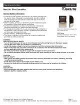
Models:
NPPSL-PSW
Picture is for illustration
purposes only. Your model
may vary.
Installation & Operation
CAUTION: Turn off electrical power at fuse or circuit breaker box before wiring fixture to the power supply.
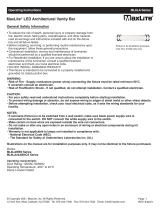
1. Drill a 1.30” diameter hole through the ceiling tile.
2. Install the sensor facing down, parallel to the mounting surface. Ensure that the rubber gasket touches the
outside surface of the ceiling tile. (FIG. 1)
3. Use the 1.3” standard tightening nut or collar to secure the sensor. Tighten the collar at a torque of 23-30
in-lbs to ensure that the IP rating is maintained. (FIG. 1)
4. Attach the lens by turning it clockwise to lock it in place.
5. Connect the NPPSL-PSW sensor with the NPP-300W following the wiring diagram. (FIG. 2)
FIG. 1
Room
Side
Tightening
Nut
Ceiling
Tile
Lens Assembly
Ceiling
Tile
Rubber
Gasket
Room Side
Tightening
Nut
Rubber
Gasket

MaxLite Inc. warrants its products for a minimum period of FIVE (5) years from the date of original purchase from
MaxLite or its authorized distributor/dealer (the “Warranty Period”), as follows: If a Product fails to operate during the
Warranty Period as a result of defects in materials or workmanship, MaxLite will, at its option, repair it, replace it with
the same or like Product.
Please refer to Maxlite’s website (at http://maxlite.com/resources/warranties) for the complete
terms and conditions of our warranty.
Limitation of Liability
THE FOREGOING WARRANTY IS EXCLUSIVE, AND IS THE SOLE REMEDY FOR ANY AND ALL CLAIMS,
WHETHER IN CONTRACT, IN TORT OR OTHERWISE ARISING FROM THE FAILURE OF PRODUCT AND IS IN
LIEU OF ALL OTHER WARRANTIES, EXPRESS OR IMPLIED, INCLUDING ALL WARRANTIES OF
MERCHANTABILITY OR FITNESS FOR A PARTICULAR PURPOSE, WHICH WARRANTIES ARE HEREBY
EXPRESSLY DISCLAIMED TO THE EXTENT PERMITTED BY LAW AND, IN ANY EVENT, SHALL BE LIMITED TO
THE WARRANTY PERIOD SPECIFIED ABOVE. THE LIABILITY OF MAXLITE SHALL BE LIMITED TO THE TERMS
OF THE EXPRESS WARRANTY SET FORTH HEREIN. IN NO EVENT WILL MAXLITE BE LIABLE FOR ANY
SPECIAL, INCIDENTAL OR CONSEQUENTIAL DAMAGES INCLUDING, WITHOUT LIMITATION, DAMAGES
RESULTING FROM LOSS OF USE, PROFITS, BUSINESS OR GOODWILL, LABOR COSTS, REMOVAL OR
INSTALLATION COSTS, DECREASE IN THE LIGHT OUTPUT OF THE LAMP, AND/OR DETERIORATION IN THE
LAMP’S PERFORMANCE, WHETHER OR NOT MAXLITE HAS BEEN ADVISED OF THE POSSIBILITY THEREOF.
UNDER NO CIRCUMSTANCES SHALL MAXLITE’S ENTIRE LIABILITY FOR A DEFECTIVE PRODUCT EXCEED
THE PURCHASE PRICE OF THAT PRODUCT. WARRANTY SERVICES PROVIDED UNDER THESE TERMS AND
CONDITIONS DO NOT ENSURE THE UNINTERRUPTED OPERATION OF PRODUCTS; MAXLITE SHALL NOT BE
LIABLE FOR DAMAGES CAUSED BY ANY DELAYS INVOLVING WARRANTY SERVICE.
This Limited Warranty gives you specific legal rights and you may also have other rights that may vary from state to
state. Because some states or jurisdictions do not allow the exclusion or limitation of liability for consequential or
incidental damages, this limitation may not apply to you.
General Wiring Diagram
© Copyright 2021. MaxLite, Inc. All Rights Reserved.
12 York Ave, West Caldwell, NJ 07006 Tel: 800-555-5629 Fax: 973-244-7333 Email: inf[email protected]
Page: 2
REV: 10/27/21
Operating Instructions NPPSL-PSW
MaxLite Network Power Pack PIR Sensor - 12V
®
Warranty Information
CAUTION: Turn off electrical power at fuse or circuit breaker box before wiring fixture to the power supply.
FIG. 2
NOTE: NPPSL-PSW should be paired with at least 1 NPP-300W (Sold Separately)
/