Page is loading ...

2024 TOWABLE
OWNER’S MANUAL

SECTION 1: INTRODUCTION
Hello, I’m Ken Walters, President and CEO of Jayco. I’d like to
personally welcome you to the Jayco Family.
The Jayco Family of Companies is comprised of four brands
- Jayco, Entegra Coach, Highland Ridge RV and Starcraft RV.
These divisions have been manufacturing RVs for over 50 years
on a tradition anchored in three pillars – Quality, Team and Family.
If you are a rst-time owner, thank you for choosing us. If you’re
a second, third or tenth owner, we are beyond pleased to have
kept you in the family.
Our mission has remained unchanged since 1968 – design and
build with innovation and safety at the forefront of all we do, and
continue to be a leading manufacturer for both towable and
motorized RVs. From the first pop-up camper built on the
Bontrager family farm, to the technology-packed lineup we build
today, we always strive for better.
Over the next few years, we hope the memories made in your
new RV are ones to remember. Thank you for taking us along for
the ride and for letting us be a part of your stories.
Sincerely,
Ken Walters
President and CEO of Jayco
Training, How-To and Walk Through Videos
Scan the QR Code to access an extensive video training series for owners of
Jayco, Starcraft & Highland Ridge brands of RVs, produced in collaboration
with the National RV Training Academy (NRVTA). The series provides an
in-depth library of videos to provide new and existing owners with training,
reference and how-to material for nearly all of the systems and components
you will utilize in your RV. VIDEO
LIBRARY

ASCEND COMMUNITY
SHARE
YOUR STORY
ASCEND
COMMUNITY
Join our Jayco Family Ascend Community
- Become a part of something bigger.
Ascend is ever-growing and is made
up of our Brand Ambassadors, owners
in groups and forums and qualied
suppliers that we partner with. Our
goal is that everyone ts into this
community in one way or another. If
you own an RV of ours and would like
to apply to be a Brand Ambassador,
you can learn more here. If you are an
owner and you want to meet others
within this family, you will nd groups
and forums we recommend that you
join. Our Ascend Community continues
to expand year after year, giving all
owners connections amongst the masses
with people with similar interests. With
over 50 brand ambassadors, hundreds
of suppliers and thousands of owners,
every one of our owners has an ally.
Get connected with your tribe.
FOLLOW
US
CHANGE OF
OWNERSHIP
GET SOCIAL WITH US!

ABOUT THIS MANUAL
This manual is a guide to operation of the features,
equipment and controls in your recreational vehicle (RV).
If you find components vary significantly from what is
described, please contact your dealer to ensure you have
the correct information. Nothing in this manual creates
any warranty, either expressed or implied, nor does it
cover every possible detail of equipment, standard or
option, installed on or in your RV.
Information, illustrations and specifications in this
manual reflect the most current available at the time
of publication approval, are subject to change and not
intended to indicate actual size.
This Owner’s Manual, Warranty Guide, and Customer
Information Packet are to be considered permanent
components of the RV. Keep them in your RV at all times
for personal reference. If the RV is sold, they should
remain with the RV for the next owner.
CUSTOMER INFORMATION PACKET
There are components that are excluded from the RV
warranty, or are warranted separately by their own
individual manufacturer’s limited warranty. The Customer
Information Packet contains the RV Warranty Guide as
welll as component manufacturer supplied manuals or
information sheets, warranty cards and/or registrations.
Consult this information for questions regarding
operating, maintenance, servicing instructions and
warranty coverage. It is important you complete and mail
warranty cards and registrations within the prescribed
time limits to avoid loss of warranty coverage.
WINGMATETM HELP
The Jayco WINGMATETM icon appears anywhere
useful information for a section may be found in
the free Jayco WINGMATETM mobile application.
Jayco WINGMATE is a user-friendly consumer app, designed not only for Jayco
owners, but for anyone camping in an RV. The app features quick-start videos,
maintenance checklists, how-to tutorials, trip and packing checklists, campsite
considerations, Jayco RV Owner’s Manuals, and an extensive glossary of RV
terms, and more. It is available for free on the Apple App Store and Google Play.
SAFETY ALERTS
Throughout this manual, certain items are labeled NOTE, NOTICE, CAUTION, WARNING, and DANGER. These signal words indicate
precautions and potential situations, which if not avoided, may result in personal injury, property damage, or damage to your RV. These
precautions are listed in the appropriate areas in this Owner’s Manual, and in the information contained in the Warranty Packet, and on safety
labels affixed to your RV. Read and follow them carefully.
National Safety Associations and organizations require many of the instructions listed. Always use the appropriate safety gear when servicing or
maintaining your RV. Please call your dealer or our customer service representatives if you are unsure how to proceed.
This is the safety alert symbol. It is used to alert you to
potential personal injury hazards. Obey all safety messages
that follow this symbol to avoid possible injury or death.
Gives helpful information.
Indicates an imminently hazardous situation that, if not avoided, will
result in death or serious injury. This alert information is limited to the
most extreme situations.
WARNINGS AND OTHER LABELS
Informational labels will be attached at various locations on the interior
and exterior of your RV. These labels are there for your guidance and
protection, and should never be tampered with or removed.
Indicates a potential situation that, if not avoided, may result in
property damage or damage to your RV.
Indicates a potentially hazardous situation that, if not avoided, may
result in minor or moderate injury. It may also be used to alert
against unsafe practices.
Indicates a potentially hazardous situation that, if not avoided, may
result in death or serious injury.
J.JAY HELP
Keep an eye out for J.Jay. He’ll be holding
a QR code, which when scanned, takes you
to info and videos specific to that section.
JAYCO UNIVERSITY
online.rvtechcourse.com/courses/jayco-university
Jayco University, developed by the
National RV Training Academy, offers
FREE video courses to familiarize you
with your RV, how the systems work in
your RV, and give you some common
troubleshooting advice. You’ll see
the University logo anywhere there is
course content that applies.
UNIVERSITY

TABLE OF CONTENTS
Page 5
SECTION 15: ADDITIONAL INFORMATION
SECTION 14: CHECKLISTS
SECTION 13: EXTERIOR
SECTION 12: INTERIOR
SECTION 11: ELECTRONICS
SECTION 10: APPLIANCES
SECTION 9: HEATING & COOLING
SECTION 8: PLUMBING SYSTEM
SECTION 7: FUEL & PROPANE SYSTEM
SECTION 6: ELECTRICAL
SECTION 5: SLIDEOUT SYSTEMS
SECTION 4: VEHICLE OPERATION
SECTION 3: PRE TRAVEL INFORMATION
SECTION 2: OCCUPANT SAFETY
SECTION 1: INTRODUCTION
2024 JAYCO FAMILY OF COMPANIES - TOWABLES OWNER’S MANUAL 24.2047700

TABLE OF CONTENTS
Page 6
WHEEL LUGS ...................................................................................22
TIRES ................................................................................................23
CHANGING A TIRE ...........................................................................24
SPARE TIRE CARRIER (IF EQUIPPED) .......................................... 24
TIRE PRESSURE MONITOR SYSTEM (TPMS) (IF EQUIPPED) ....24
SETTING UP YOUR RECREATION VEHICLE .................................25
CAMPSITE HOOK-UP ......................................................................25
SEASONAL SET-UP (BUNGALOWS ONLY) ....................................26
CARGO RAMP DOOR ......................................................................28
LOADING THE CARGO AREA ..........................................................29
PATIO DECK - REAR (IF EQUIPPED) ..............................................29
PATIO DECK – SIDE (IF EQUIPPED) ...............................................30
AWNINGS (IF EQUIPPED) ............................................................... 31
SECTION 5: SLIDEOUT SYSTEMS
ELECTRIC SLIDE ROOM(S) (IF EQUIPPED) .................................. 36
SECTION 6: ELECTRICAL
THE ELECTRICAL SYSTEM .............................................................38
12-VOLT DC SYSTEM .....................................................................38
LOAD CENTER .................................................................................39
EXTERIOR LIGHTS (IF EQUIPPED) ................................................39
REPLACING LIGHTING ....................................................................39
COMMAND CENTER ........................................................................40
GFCI RECEPTACLE ......................................................................... 40
JAYCOMMAND®/TRAVELLINK® SYSTEM (IF EQUIPPED) .............41
BMPRO MINI SYSTEM (IF EQUIPPED) ...........................................43
JAYVOICE / DIRECTOR (IF EQUIPPED) ......................................... 44
120-VOLT AC ELECTRIC SYSTEM ..................................................45
120-VOLT 30-AMP AC ELECTRIC SYSTEM (IF EQUIPPED) ..........45
120-VOLT 50 AMP AC ELECTRIC SYSTEM (IF EQUIPPED) .......... 45
TESTING CAMPSITE POWER CONNECTION ................................45
POWERED CORD REEL (IF EQUIPPED) ........................................46
INVERTER (IF EQUIPPED) ..............................................................46
CONNECTING POWER CORD(S) ...................................................46
POWER CONVERTER .....................................................................47
120-VOLT CIRCUIT BREAKERS ...................................................... 48
APPROXIMATE ELECTRICAL LOAD RATINGS .............................. 48
AUXILIARY BATTERY (CUSTOMER SUPPLIED) ............................49
DISCONNECT SWITCH (IF EQUIPPED)..........................................49
GENERATOR (IF EQUIPPED) ..........................................................50
SOLAR PREP (IF EQUIPPED) .........................................................51
SOLAR PACKAGE (IF EQUIPPED) ..................................................52
SECTION 1: INTRODUCTION
ASCEND COMMUNITY ......................................................................3
ABOUT THIS MANUAL ....................................................................... 4
CUSTOMER INFORMATION PACKET ............................................... 4
WINGMATETM HELP ............................................................................4
J.JAY HELP ......................................................................................... 4
SAFETY ALERTS ................................................................................4
WARNINGS AND OTHER LABELS .................................................... 4
SECTION 2: OCCUPANT SAFETY
SECONDARY MEANS OF ESCAPE (EXIT WINDOW) ......................8
FIRE SAFETY .....................................................................................8
FIRE EXTINGUISHER ........................................................................8
SMOKE ALARM ..................................................................................8
COMBINATION CARBON MONOXIDE /PROPANE ALARM ..............9
FORMALDEHYDE ...............................................................................9
CONDENSATION ................................................................................9
EXTENDED OR FULL TIME USAGE ..................................................9
COLD WEATHER USAGE .................................................................. 9
SECTION 3: PRE TRAVEL INFORMATION
TOW VEHICLE ..................................................................................11
VEHICLE LABELS ............................................................................. 11
REAR BUMPER ................................................................................ 12
CARGO CARRYING ACCESSORY RECEIVER (IF EQUIPPED) .....12
BIKE RACK (IF EQUIPPED) ............................................................. 12
LOADING YOUR RV ......................................................................... 12
TRAVEL TRAILER HITCH (CUSTOMER SUPPLIED) ...................... 13
FIFTH WHEEL PIN BOX (CUSTOMER SUPPLIED) ........................14
WEIGHING YOUR TOW VEHICLE AND RV .....................................15
WIRE HARNESS/CONNECTOR PLUG ............................................15
SECTION 4: VEHICLE OPERATION
TOWING ............................................................................................17
TOWING BEHIND YOUR RV ............................................................18
ENTRANCE DOOR STEP(S) ..........................................................19
STEP LIGHT ......................................................................................19
STOWABLE ENTRANCE DOOR STEP ............................................19
ENTRANCE DOOR ...........................................................................19
LEVELING SYSTEM (IF EQUIPPED) ...............................................20
STABILIZERS ....................................................................................20
TANDEM AXLE FLEX EQUALIZER (IF EQUIPPED) ........................21
EMERGENCY STOPPING ................................................................22
EMERGENCY TOWING ....................................................................22

TABLE OF CONTENTS
Page 7
SECTION 7: FUEL & PROPANE SYSTEM
EXHAUST GAS FUMES ...................................................................55
PROPANE GAS SYSTEM .................................................................55
PROPANE USE AND SAFETY .........................................................57
USING THE FUEL STATION (IF EQUIPPED - SEISMIC ONLY) ...... 58
SECTION 8: PLUMBING SYSTEM
PLUMBING SYSTEM ........................................................................61
MONITOR PANEL ............................................................................. 61
FRESH WATER SYSTEM .................................................................62
FRESH WATER CONNECTIONS ..................................................... 63
WATER PURIFICATION SYSTEM (IF EQUIPPED) ..........................64
SPRAY PORT (IF EQUIPPED) ..........................................................64
TOILET ..............................................................................................64
DRAINING THE FRESH WATER SYSTEM ...................................... 65
UTILITY CENTERS ........................................................................... 66
WATER HEATER ...............................................................................68
ON DEMAND WATER HEATER (IF EQUIPPED)..............................69
FAUCETS ..........................................................................................70
BATHROOM TUB / SHOWER ...........................................................70
OUTSIDE SHOWER (IF EQUIPPED) ............................................... 70
BLACK/GREY WATER SYSTEM AND TANKS ................................. 71
BLACK AND GREY TANK DRAINS ..................................................72
MACERATOR PUMP SYSTEM (IF EQUIPPED) ...............................73
BLACK TANK FLUSH (IF EQUIPPED) ..............................................74
TANK HEATERS (IF EQUIPPED) ..................................................... 74
SANITIZING/WINTERIZING THE PLUMBING SYSTEM ..................75
SECTION 9: HEATING & COOLING
AIR CONDITIONER .........................................................................80
POWER ROOF VENT (IF EQUIPPED) .............................................80
FIREPLACE (IF EQUIPPED) ............................................................80
CEILING FAN (IF EQUIPPED) ..........................................................81
FURNACE ....................................................................................... 81
SECTION 10: APPLIANCES
MICROWAVE ....................................................................................82
COOKTOPS, RANGE AND OVEN (IF EQUIPPED) ..........................82
RANGE HOOD (IF EQUIPPED) ........................................................83
COOKING SAFETY ...........................................................................83
REFRIGERATOR ..............................................................................83
JAYPORTTM AND GAS BBQ GRILL ..................................................84
PROPANE GRILL QUICK COUPLER ............................................... 84
OUTSIDE KITCHEN (IF EQUIPPED) ................................................84
TAILGATER CAMP KITCHEN (IF EQUIPPED - SEISMIC) ...............85
WASHER/DRYER PREP (IF EQUIPPED) ........................................86
CENTRAL VACUUM SYSTEM (IF EQUIPPED) ................................86
SECTION 11: ELECTRONICS
WINEGARD® AIRTM 360 ANTENNA ...................................................89
WINEGARD® GATEWAY ROUTER (IF EQUIPPED) .........................89
CAMERA PREP/CAMERA (IF EQUIPPED) ...................................... 90
EXTERIOR SLIDING / PIVOTING TV (IF EQUIPPED) .....................90
SECTION 12: INTERIOR
CLEANING THE INTERIOR ..............................................................91
SOFAS AND DINETTES ...................................................................91
TOKYO BED (IF EQUIPPED) ...........................................................93
POWER BUNK BED (SEISMIC CARGO BAY) ................................. 93
MURPHY BED (IF EQUIPPED) ........................................................95
STANDARD BED STORAGE ............................................................ 95
BUNK BED AND LOFT LADDERS (IF EQUIPPED)..........................96
BED RAILS ........................................................................................96
SECTION 13: EXTERIOR
CLEANING THE EXTERIOR .............................................................98
CLEANING SLIDE-OUT SEALS .......................................................99
E-Z LUBE® OR SUPER LUBETM AXLE (IF EQUIPPED) .................100
EXTERIOR ROOF AND SIDEWALL VENTS ..................................100
WINDOWS ......................................................................................100
EXTERIOR LADDER (IF EQUIPPED) ............................................100
SEALANTS ......................................................................................101
SECTION 14: CHECKLISTS
TRAVEL CHECKLIST ......................................................................103
RV STORAGE CHECKLIST ............................................................104
SECTION 15: ADDITIONAL INFORMATION
FEATURED COMPONENTS QUICK REFERENCE CHART ..........105
HELPFUL LINKS .............................................................................106

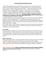
OCCUPANT SAFETY
Lever style latch
1. Remove the screen by pulling the red tab
(upper right arrow).
2. Pull the lever out from the sash clamps.
3. Swing the lever out so it is positioned
straight out from the window.
4. Push the lever (and window) out to open.
5. Exit the RV.
SECONDARY MEANS OF ESCAPE (EXIT WINDOW)
Your RV has been equipped with a window(s) that serves as a
secondary means of escape. The window(s) will allow a quick exit
from the RV during an emergency if access to the main entrance door
is not available. It is easily identified by the red latches and label.
Do not remove the EXIT window label(s).
When parking your RV, make sure the egress
window is not blocked by trees or other obstacles.
Make sure the ground below the window is solid
and can be used as an escape path.
Practice opening the window before an emergency occurs, and make
sure all occupants know how to operate it.
(See Page 10)
Exit Window Label
All windows must be closed and locked while the RV is in transit.
Your RV may be equipped with one of the following exit window styles:
Flip latch style (2 per window)
1. Push up on the front lip of the latch and the
latch unfolds.
2. Push up on the front lip of the latch again to
unhook the latch from the window.
3. When both latches are released, push out on
the window, which is hinged at the top. Exit
the RV.
The screen does not need to be removed from the window.
Slider window latch style
1. Pull the lever down to unlock the
window.
2. Slide the window to the right to
open.
3. Exit the RV.
The screen does not need to be removed from the window.
SECTION 2: OCCUPANT SAFETY
FIRE SAFETY
If a fire does start, follow these basic safety rules:
1. Evacuate everyone from the RV immediately and call 911.
2. Make sure everyone is accounted for.
3. Get clear of the RV and allow the fire department to handle the
emergency.
(See Page 10)
FIRE EXTINGUISHER
A dry chemical fire extinguisher has been installed by the entrance
door. It is suitable for extinguishing small fires of the Class B or C
type (flammable liquids and electrical) only.
We suggest you become thoroughly familiar with the operating
instructions displayed on the side of the fire extinguisher.
For information on fire extinguisher use, refer to the fire extinguisher
user’s manual included in your customer information packet.
(See Page 8)
SMOKE ALARM
A smoke alarm is installed in every RV for your safety. Most detectors
are powered by a 9 volt battery that should be inspected and
replaced as needed. Keep the smoke alarm free of dust. Refer to
and follow in detail the safety, testing, troubleshooting, maintenance,
and smoke alarm expiration and replacement information found in
the manufacturer’s user guide located in your customer information
packet.
(See Page 10)
Page 8

OCCUPANT SAFETY
COLD WEATHER USAGE
When used in freezing or below freezing temperatures, the
precautions should be taken:
• Fresh water and drainage systems - preparations to avoid
freeze-ups.
• Propane gas (if equipped) and sufficient power is needed
for protection from possible freeze-ups on the propane gas
regulator. Keep in mind that more frequent furnace operation will
substantially increase battery draw and propane gas use.
• During cool weather usage, ventilation or addition of a
dehumidifier may be required to reduce condensation.
• Check outside extrusions on compartment doors, locks, slide
outs, windows, vents, etc., for frozen moisture before operating
to avoid damage to parts.
COMBINATION CARBON MONOXIDE /PROPANE
ALARM
Your RV is equipped with a combination
carbon monoxide (CO) / propane alarm
that is listed for use in RVs. The alarm
is directly wired to the 12-volt electrical
system, with continuous power being
supplied by the RV batteries. If the
battery cable is disconnected at the
battery terminals, the combination
alarm will not work.
Be sure to read, understand and follow the owner’s information from
the manufacturer of the combination CO/propane alarm. This includes
information regarding the limited life of the alarm.
Carbon monoxide (CO) is an insidious poison. It is a colorless,
odorless and tasteless gas. Many cases of reported carbon monoxide
poisoning indicate while victims are aware they are not well, they
become so disoriented they are unable to save themselves by
either exiting the RV or calling for assistance. Young children and
household pets may be the first affected.
The following symptoms are related to carbon monoxide poisoning
and should be discussed with all members of the household:
• Mild exposure: Slight headache, nausea, vomiting, fatigue (often
described as “flu-like” symptoms).
• Medium exposure: Severe throbbing headaches, drowsiness,
confusion, fast heart rate
• Extreme exposure: Unconsciousness, convulsions, cardio-
respiratory failure, death
Your combination carbon monoxide/propane alarm is designed to
detect the toxic carbon monoxide fumes that result from incomplete
combustion, such as those emitted from appliances, furnaces,
fireplaces and auto exhaust.
Maintenance
Vacuum the alarm cover at least once a year. Clean the cover by
hand using a cloth dampened in clean water. Dry with a soft cloth.
Do not spray the front panel of the alarm with cleaning agents or
waxes. This action may damage the sensor causing an alarm or
cause the alarm to malfunction. Do not paint the face of the alarm.
Refer to the carbon monoxide/propane alarm manufacturers user’s
manual provided with your RV for additional information on functions
and alarm testing.
Test the alarm operation after the RV has been in storage, before
each trip and at least once per week during use.
Repair or replace the combination carbon monoxide/propane alarm
when the alarm no longer functions.
The carbon monoxide/propane alarm manufacturer strongly
recommends replacement of the detector five years after the date of
purchase.
Carbon monoxide/ Propane alarm
(alarm may vary)
(See Page 10)
FORMALDEHYDE
Some components in the RV contain formaldehyde-based adhesives
that may release formaldehyde fumes into the air for an unknown
period of time. Individuals who are allergic to formaldehyde gas
fumes may experience irritation to eyes, ears, nose and throat. Indoor
air quality may also be affected by leaving your RV closed for a period
of time.
To aid in dissipation, ventilate the RV by opening all windows and
circulate the air with a fan.
CONDENSATION
Condensation is a natural phenomenon. The amount of condensation
will vary with climate conditions, particularly the relative humidity.
Condensation occurs because there is water vapor present in the air.
When the temperature reaches the “dew point” the water vapor in the
air condenses and changes to a liquid form.
Proper ventilation or the use of a dehumidifier (customer supplied) will
assist in controlling the condensation. Suggestions to eliminate warm
moist air:
• Crack open windows and roof vents to allow warm moist air to
escape.
• Open the bath roof vent (if equipped) approximately 1/2” when
showering.
• Use the range hood fan (if equipped) when cooking or washing
dishes.
• Avoid hanging wet towels (or clothes) inside the RV to dry.
• If found in cabinets or closets, open the doors slightly to provide
ventilation.
(See Page 10)
EXTENDED OR FULL TIME USAGE
Unless specifically marked for full time use, your RV is not intended
for use as full-time quarters or a permanent residence. Continuous
living in your RV could cause accelerated wear and damage to the
various components.
(See Page 10)
Page 9
OCCUPANT SAFETY
2

OCCUPANT SAFETY OCCUPANT SAFETY DANGER
FIRE SAFETY (Page 8)
Do not attempt to use water to put out the fire. Water can spread
some types of fire, and electrocution is possible with an electrical fire.
FIRE EXTINGUISHER (Page 8)
Do not turn the electrical power back on or plug in any appliances
after the use of a fire extinguisher. Please refer to the fire
extinguisher’s user manual for further instructions on maintenance
and clean up.
CARBON MONOXIDE /PROPANE ALARM (Page 9)
If alarm is triggered, exit the vehicle immediately and call for
assistance. The gases may dissipate before help arrives, but it is
imperative that the source of the leak is found and repaired.
Your combination carbon monoxide/propane alarm is designed to
detect the toxic carbon monoxide fumes that result from incomplete
combustion, such as those emitted from appliances, furnaces,
fireplaces and auto exhaust as well as propane leaks. Consult the
user’s guide for instructions and audible/visual warning details.
OCCUPANT SAFETY WARNING
CONDENSATION (Page 9)
Condensation may cause dampness, mildew, mold, staining and, if
allowed to continue, it may result in damage to the recreation vehicle
(damage caused by condensation is not warrantable). It can also lead
to mold or mildew issues, which could be a health hazard.
CARBON MONOXIDE /PROPANE ALARM (Page 9)
Do not cover or obstruct the carbon monoxide/propane alarm with
anything that could prevent gas from entering the alarm.
Actuation of this detector indicates the presence of carbon monoxide
which can kill you. This alarm is not designed to detect smoke, fire or
gases other than carbon monoxide and propane.
The carbon monoxide detector installed is intended for use in
ordinary indoor locations of recreation vehicles. It is not designed to
comply with Occupational Safety and Health Administration (OSHA)
commercial or industrial standards.
Individuals with medical problems may consider using warning
devices that provide audible and visual signals for carbon monoxide
concentrations under 30 PPM.
This alarm will only indicate the presence of carbon monoxide gas at
the sensor. Carbon monoxide gas may be present in other areas.
The ultimate responsibility for protection against toxic carbon
monoxide fumes rests solely on you. Installing a carbon monoxide/
propane alarm is just the first step in protecting your family from toxic
carbon monoxide poisoning.
Do not disconnect the battery or the alarm.
Never turn the 12-volt battery disconnect control to the off position
and disconnect the battery cable to silence an alarm. The alarm will
automatically sense when the level of carbon monoxide in the air
reaches below dangerous levels. You should stay outside the vehicle
in fresh air until the alarm is silenced. When the alarm sounds, do
not stand too close to the alarm. The sound produced by the alarm is
loud (85db) because it is designed to wake a person in an emergency.
Prolonged exposure to the alarm at a close distance may be harmful
to your hearing.
OCCUPANT SAFETY CAUTION
SECONDARY MEANS OF ESCAPE - EXIT WINDOW (Page 8)
Exercise care when opening the exit window. If opened too far, it may
come off the hinge. This may result in damage to the unit or window.
EXTENDED OR FULL TIME USAGE (Page 9)
Continuous or permanent living in your recreation vehicle may
affect your warranty coverage and may void the “Limited Warranty”
applicable to your vehicle.
FIRE EXTINGUISHER (Page 8)
Do not check the pressure, test or practice using the fire extinguisher
by squeezing the trigger, even briefly. The fire extinguisher is not
rechargeable or refillable. Once used, it will gradually lose pressure
and will not be fully charged for use in an emergency.
SMOKE ALARM (Page 8)
This smoke alarm will not alert hearing impaired residents. Special
alarms with flashing strobe lights are recommended for the hearing
impaired
Only use the replacement battery recommended by the smoke
detector manufacturer. The smoke detector alarm may not operate
properly with other batteries. Never use a rechargeable battery as it
may not provide a constant charge. Never disconnect the battery to
silence the alarm.
Test the smoke alarm operation after the vehicle has been in storage,
before each trip and at least once per week during use. Do not
disconnect the battery or the alarm.
Page 10

PRE TRAVEL INFORMATION
SECTION 3: PRE TRAVEL INFORMATION
TOW VEHICLE
If you plan to tow your RV with a tow vehicle you already own, or if
you plan to purchase a new one, make sure the Gross Vehicle Weight
Rating (GVWR) of your RV does not exceed your tow vehicle’s towing
rating. Ask your automotive dealer how to obtain a copy of information
that deals with towing considerations, with or without an optional
vehicle tow package.
VEHICLE LABELS
Decals and data plates used throughout the RV aid in its safe and
efficient operation; others give service instructions. Read all decals,
data and instruction plates before operating your RV. Any decal, data
or instruction plate painted over, damaged or removed should be
replaced.
Keep a record of the 17-digit chassis vehicle identification number
(VIN), the 8-digit serial number, and your license number in the event
theft or vandalism requires you to supply this information to the
authorities.
WEIGHT TERMS
GAWR - Gross Axle Weight Rating: The value
specified by the vehicle manufacturer as the
load-carrying capacity of a single axle system, as
measured at the tire-to-ground interfaces. This is the
total weight a given axle sytem is capable of carrying.
GCWR - Gross Combined Weight Rating: The value specified by
the trailer manufacturer as the maximum allowable loaded weight of
the trailer including full propane cylinders, a full load of water, and
full generator fuel if applicable.
GVWR - Gross Vehicle Weight Rating: The value specified by
the manufacturer as the maximum permissible weight of the fully
loaded trailer.
OCCC - Occupant And Cargo Carrying Capacity: Is equal to the
GVWR of the trailer, minus the:
• Weight of the trailer (as completed at the factory).
• Weight of all personal cargo.
• Weight of a full tank (or tanks) of propane (if applicable).
(See page 16)
UNIVERSITY
• Full weight of potable water, including the water heater.
Additions to or other changes made to the trailer after it left the
factory will affect (reduce) the OCCC.
UVW - Unloaded Vehicle Weight: The weight of the trailer
as manufactured at the factory with the weight of a full tank (or
tanks) of propane.
WEIGHT AND CAPACITY LABELS
The following labels are typically located on the roadside front corner
of the RV. An additional Cargo Carrying Capacity label may also be
located on or near the entry door.
CCC Label (Cargo Carrying Capacity):
The upper portion of this yellow label is federally required and
includes the maximum Cargo Carrying Capacity that may be placed
in or on the trailer as it was manufactured and weighed before
leaving the factory. This maximum capacity would not include the
weight of a full fresh water tank.
Additions or other changes made to the trailer after it leaves the
factory will affect (reduce) the CCC.
The middle portion of this label is provided voluntarily and indicates
the weight value of the trailer as it was manufactured and weighed
CCC Label Example
XXXXXXXXXXXXXXXXX
XXX XXXX
XXX XXX
XXX
XXX
XX X X
Labels for the Canadian market are white and weight measurements
include the weight of a full water heater and fresh water tank.
Page 11
PRE TRAVEL INFORMATION
3

PRE TRAVEL INFORMATION
REAR BUMPER
The rear bumper of your RV is not designed to carry cargo. Items that
extend beyond the bumper or weigh over 100 lbs. (45kg) will place
undo strain on the bumper. The 100 lb. bumper capacity includes the
weight of the spare tire (if equipped).
CARGO CARRYING ACCESSORY RECEIVER (IF
EQUIPPED)
(See page 16)
Some items may fall within the given weight range, (IE: bike racks)
however, they can still cause damage. In addition, extra weight
behind the axle may reduce the hitch weight which can adversely
affect handling.
Receiver is for cargo carrying accessories ONLY. DO NOT tow
any trailer or other vehicle. Load Limit for this receiver is 300 lbs.
maximum. Use for towing or exceeding load limit will void the
warranty. Failure to follow the instructions can cause the carrier to
collapse or items to fall which could cause an accident resulting in
death or serious injury.
BIKE RACK (IF EQUIPPED)
Your RV may be equipped with a bike rack. Refer to the bike
rack manufacturer’s owner’s manual for detailed safety and user
information.
(See page 16)
at the factory. It includes full propane tanks and full generator fuel
(if equipped).
For example, if the tires are rated at 2,000 lbs. each x 4 tires =
8,000 lbs. and the RV has a GVWR of 9,000 lbs. with a tongue
weight of 1,200 lbs. The actual weight on the RV tires is (9,000 –
1,200) which equals 7,800 lbs. which is within the weight rating of
the tires.
The Federal Certification Label
The Federal Certification Label is required by the government
to verify the trailer complies with all motor vehicle standards for
Canada and the United States. It includes the following information:
Manufacturer name, VIN, GVWR, GAWR (front/rear), tire and rim
sizes and cold tire inflation pressures.
Tire and Loading Label
Tire and Loading Label provides information on the tire sizes, cold
tire inflation pressures, the VIN and maximum cargo capacity. The
maximum cargo capacity listed on the label does not include the
weight of a full load of water.
If you have further questions, please contact your dealer or our
Customer Service department.
LOADING YOUR RV
Store and secure all loose items inside the RV before traveling.
Distribute cargo side-to-side so the weight on each tire does not
exceed one-half of the GAWR for either axle. Make sure any tie down
straps (if equipped) on appliances or furniture are secure. Load
heavy objects on the floor, or as low as possible.
The total weight capacity of the tires on your RV can be less than the
GVWR. The calculation for the actual weight on the RV tires does
not include the tongue weight. Your tow vehicle, not the RV tires, is
actually carrying the tongue weight.
XXXXXXXXXXXXXXXXX
XX/XX
RV MANUFACTURER NAME
XX
XX
XX XX XX XX
XX XX
XXXXX/XXXXXX
XXXXX/XXXXXX XXXX X
XXXX X
Federal Certification Label Example
XXX XXXX
XXXXXXXXXXXXXXXXX
XXXXX/XXXXXX
XXXXX/XXXXXX
XXXXX/XXXXXX
XXX
XXX
XXX
XX
XX
XX
Tire and Loading Label Example
(See page 16)
Page 12

PRE TRAVEL INFORMATION
TRAVEL TRAILER HITCH (CUSTOMER SUPPLIED)
Hitch selection affects the towing and handling characteristics of your
RV. There are many kinds of hitches available and assuring that you
have the correct hitch installed is critical to safe towing.
Ask your dealer about the proper class and type of hitch you need for
your individual tow vehicle/RV combination. A travel trailer requires a
frame mounted hitch.
The hitch class rating is based on the capacity that hitch has for
towing and a weight classification. The weight classification is
determined from the hitch’s weight carrying capacity (the tongue
weight on a travel trailer). Before selecting a hitch, you must know
your GVWR and tongue weight. The rating of the hitch package
purchased should be equal to or greater than the RV’s GVWR
and the hitch weight.
Equipment that sometimes gives autos, trucks and sport utility
vehicles a softer ride can accentuate swaying when pulling an
RV. Suspension that is too stiff will increase vibration, bounce and
accelerate wear of your tow vehicle and RV combination.
Your RV manufacturer cannot be responsible for the suspension
system of any tow vehicle. There are a variety of tow vehicle
suspension systems available that will affect the ball height,
stability and levelness of a hooked up RV. Make sure your dealer
is aware of the tow vehicle you are using so a compatible hookup is
achieved.
Travel trailer hitch weight
Maintain the proper tongue weight of the trailer. Stay within the target
range of 10%-15% of the overall gross weight (travel trailer weight
plus contents).
Travel trailer hitch height and hitch ball
To determine the hitch height for your model, make sure that the
trailer is level. When the loaded RV is hitched to the tow vehicle,
check the hitch ball height. This can be determined by
measuring the distance from the center of the hitch
ball to the ground. Record this number in the box for
future reference.
Adjust the hitch assembly so that the tow vehicle and the trailer are
essentially level. A high hitch will transfer weight behind the axles and
cause the vehicle to fishtail. A low hitch will transfer additional weight
to the hitch. Refer to the hitch manufacturer instructions to adjust the
weight-distributing hitch to the proper height.
If you have additional questions, consult with your dealer. Make
certain your dealer is aware of the tow vehicle you are using so
a compatible hookup is achieved. Depending on the model, your
required travel trailer hitch ball diameter is either 2” or 2-5/16” (consult
your dealer for assistance).
Travel Trailer Hitching Procedure
The following procedure will help to assist you in
securely hooking up your RV to your tow vehicle.
1. Chock the trailer wheels.
(See page 16)
Hitch
height is:
2. Turn the tongue jack crank (or press EXTEND/UP on electric
jacks) to raise the travel trailer tongue above the hitch ball.
3. Open the coupler latch on the travel trailer hitch.
4. Back the tow vehicle into the proper position.
5. Turn the tongue jack crank (or press RETRACT/DOWN on
electric jacks) to lower the coupler onto the hitch ball.
6. Close the coupler latch after it is completely seated.
7. Install the (customer supplied) weight distributing bars
(equalizers) as directed by the OEM (if equipped).
8. Remove any dolly wheel or platform and retract the tongue jack
to its maximum height off of the ground.
9. Attach the breakaway switch cable to the tow vehicle.
10. Attach the safety chains (See “Travel Trailer Safety Chains” on
page 14).
11. Plug in your wire harness/connector plug from the tow vehicle to
the travel trailer.
12. Walk around the RV to verify exterior lights are working correctly.
13. Remove the trailer wheel chocks.
Travel Trailer Weight Distributing System (customer supplied)
This system provides a more stable tow vehicle/RV combination.
It will distribute the weight evenly to the tow vehicle front and rear
axles and the trailer axle. Consult with your dealer for information
on requirements and operation of this system. Be certain your tow
vehicle can carry the hitch weight.
Travel Trailer Sway Control (customer supplied)
Sway control devices are available to reduce the sway produced by
crosswinds, air displacement caused by other vehicles passing you
in transit, incorrect weight distribution, excessive speed, the RV tires
dropping onto the shoulder of the road, etc. Have a sway control
device installed to help control side-to-side movement and keep sway
in check. Consult your dealer for additional information.
Suggestions for sway situations:
• Slowly ease your foot off
the accelerator.
• Turn the steering wheel
as little as possible.
Natural lag time reaction
when counter-steering
to correct sway could
possibly make it worse.
• As soon as possible, stop to determine the cause of the sway.
Check all equipment and load distribution. If the problem
cannot be solved immediately, contact your dealer for a service
appointment. Reduce your speed until the issue is resolved.
If using a brake actuator, refer to the manufacturer’s owner’s manual
for detailed and important hitching and safety information.
Sway Control/ Weight Distribution Hitch Example
Page 13
PRE TRAVEL INFORMATION
3

PRE TRAVEL INFORMATION
Travel Trailer Safety Chains
Your RV is equipped with chains to meet SAE standard requirements
for maximum gross trailer weight. Always have the safety chains
attached when towing. Install them as shown below so they do not
restrict sharp turns, but tight enough so they do not drag on the
ground.
Crisscross the left safety chain under the coupler and attach to the
right mounting slot in the trailer hitch; repeat with the right safety
chain. Slack for each length should be the same but not more than
necessary to permit the vehicle to turn at its minimum radius, but tight
enough not to drag on the ground.
Your RVs emergency brake line should never be installed to the safety
chain or safety chain hook. Attach the emergency brake line to a
permanent fixture on the tow vehicle with a sturdy carabiner or other
strong removable connector.
1. Inspect chains to determine if they are
properly attached to the trailer frame. 2. Connect driver side chain to passenger
side mounting point on tow vehicle hitch.
3. Connect passenger side chain to
driver side mounting point on tow vehicle
hitch. Chains should cross but not touch
the ground.
4. Properly mounted safety chains.
Trailer plug and emergency brake line
attached. Trailer jack raised.
FIFTH WHEEL PIN BOX (CUSTOMER SUPPLIED)
Hitch selection affects the towing and handling characteristics of
your RV, and is critical to safe towing. Talk to your dealer about the
appropriate hitch for your individual tow vehicle/RV combination. A
fifth wheel requires a pin box hitch bolted directly to the floor of the
truck bed through the frame.
Your tow vehicle’s bed length will also determine hitch options. Using
the wrong hitch on a short bed truck, as an example, could cause
damage to the truck when the front edge of the trailer swings into the
truck cab during tight turns while backing up.
The rating of the hitch package purchased should be equal to or
greater than the RV’s GVWR and the pin box rating.
(See page 16)
Suspension equipment that gives trucks and sport utility vehicles
a softer ride can often accentuate swaying when pulling an RV.
Conversely, suspension that is too stiff will increase vibration, bounce,
and accelerate wear of your tow vehicle and RV combination. Your
RV manufacturer cannot be responsible for the suspension
system of any tow vehicle. There are a variety of tow vehicle
suspension systems available that will affect the pin box height,
stability and levelness of a hooked up RV.
The fifth wheel factory installed pin box is not interchangeable.
Maintain the proper pin box weight on the hitch. A low hitch will
transfer additional weight to the hitch. Refer to a professional to
adjust the hitch to the proper height.
If you have additional questions, consult with your dealer. Make
certain your dealer is aware of the tow vehicle you are using so a
compatible hookup is achieved.
Fifth Wheel Hitching Procedure
The following procedure will help to assist you in securely hooking up
your RV to your tow vehicle.
1. Chock the trailer wheels.
2. Make sure the hitch lever is in its open
or “cocked” position unless it has been designed to open
automatically.
3. Adjust the fifth-wheel travel trailer pin to the proper height by
raising or lowering the landing gear.
4. Lower the tailgate, if applicable.
5. Back the truck so the hitch encircles the fifth-wheel/travel trailer
pin. You may need to adjust the trailer pin height to be even with
or slightly below the coupler.
6. A gentle contact of the hitch saddle jaws against the pin will
cause the mechanism to close.
7. Secure the hitch lever as specified by the manufacturer.
8. Put the truck in drive (DO NOT press on the accelerator) and
‘bump’ the hitch to make sure it is locked. After which, put the
truck back in park.
9. Be sure to raise the fifth-wheel landing gear all the way up.
10. Attach the breakaway switch cable to the tow vehicle.
11. Plug the wire harness/connector plug from the tow vehicle to the
fifth wheel.
12. Remove the wheel chocks from the trailer wheels.
Fifth wheel landing gear can be operated manually. The fifth wheel
landing gear must be fully retracted before moving or towing the RV to
prevent damage.
(See page 16)
5th Wheel Hitch Example
Hitch Pin or
King Pin
5th Wheel Receiver Example
Saddle
Hitch
Lever
Page 14

PRE TRAVEL INFORMATION
WIRE HARNESS/CONNECTOR PLUG
A 7-way wire harness/connector plug is wired into your trailer to
connect electrical power from the tow vehicle for travel. This supplies
power to the RV brakes, taillights, clearance lights, turn signals, brake
lights, etc. Wiring to operate your brakes must be the same size in
both the tow vehicle and RV (the RV brake wiring is 12-gauge wire).
The connector plug may build up corrosion with extended use. It
should be cleaned periodically to insure good electrical contact. Make
sure the connector plug is kept clean and protected from road
elements as you travel.
A 12V circuit tester is recommended to verify the trailer connections.
7-Way Trailer Plug (Cord End)
(White) Ground
(Yellow) Back Up Lights
(Red) Stop &
Left Turn
(Green) Running
Lights
(Black) Auxiliary +12V
Battery Charge Line
(Brown/Orange)
Stop & Right Turn
(Blue) Trailer
Brakes
WEIGHING YOUR TOW VEHICLE AND RV
When the RV is fully loaded it should be weighed. The actual weight
of the RV, all options, liquids, the hitch weight, and your personal
cargo is important for you to know so you do not exceed the GVWR.
Two important factors when loading your RV are total weight and
balance.
It is imperative that you verify compliance within all applicable weight
ratings. Overloading your RV will void the Towable Limited Warranty
and the warranties of many component part manufacturers.
Periodically weigh your RV at a public scale to determine proper
load distribution. To obtain the side-to-side weights, there needs to
be enough space on either side of the scale to accommodate the RV
being partially off the scale. Keep in mind that individual scales
will operate differently.
To weigh your tow vehicle and RV
Your RV must be weighed loaded as you would drive with it with food,
clothing, fuel, water (if dry camping), propane, supplies, etc.
1. Weigh the RV, including the tongue weight, while detached from
the tow vehicle. This actual overall weight must be less than or
equal to the GVWR for safe operation. If the overall weight is
greater than the GVWR, some contents must be removed until
the actual overall weight is less than or equal to GVWR.
2. Hitch the RV to your tow vehicle. Weigh the RV and the tow
vehicle to determine the GCW. Make sure that this rating is less
than or equal to the GCWR as specified by the manufacturer of
your tow vehicle. If this overall weight is greater than the GCWR,
some contents must be removed to bring the combination into
compliance with the listed ratings.
3. Weigh the RV while attached to but excluding the tow vehicle.
This will result in the actual weight that is exerted on all of the RV
tires. This weight may be subtracted from the overall RV GVWR
to determine the actual “tongue” weight.
4. With the RV still attached to the tow vehicle, weigh each wheel
position separately to ensure each tire is not overloaded.
To determine the wheel position weight
1. Pull the RV onto the scale so only one side’s tire(s) is on the
scale. Record the weight. Your RV must remain as level as
possible (even though one side is not physically on the scale).
2. To calculate the opposite side RV wheel position weight, subtract
the first side’s weight from the weight determined in step #3.
If there is a difference in the weights on one side of the RV as
compared to weights on the other side, rearrange cargo to try to
equalize the load and not overburden the suspension on one side.
Once actual weights are obtained, compare them to the Weight
Information Label weight ratings to ensure you are below the posted
minimum ratings.
See “WEIGHT TERMS” on page 11 and “LOADING YOUR RV” on
page 12 for important weight information.
(See page 16)
Page 15
PRE TRAVEL INFORMATION
3

PRE TRAVEL INFORMATION
PRE TRAVEL INFORMATION CAUTION
PRE TRAVEL INFORMATION WARNING
VEHICLE LABELS (page 11)
The factory-installed weight labels are specific to the recreation
vehicle for which they are supplied and are not interchangeable. Do
not remove these labels from your vehicle. If labels are missing
contact your dealer or Customer Service for replacements.
Do not exceed any applicable weight ratings. Doing so could damage
your RV or tow vehicle and adversely affect handling and braking
characteristics.
LOADING YOUR RECREATION VEHICLE (page 12)
Never load the RV in excess of the GAWR for either axle. Overloading
your RV may result in adverse handling characteristics and damage
to the RV.
DO NOT EXCEED YOUR GVWR! This means you should weigh your
RV as loaded for your normal travel to determine the actual weight.
If you exceed the GVWR, you MUST remove items from the RV, or
drain liquids, then re-weigh the vehicle to ensure you have achieved
a safe weight. Do not travel with full grey/black holding tanks. This not
only wastes gas but, depending upon the location of the grey or black
holding tanks, can affect handling characteristics
Your recreation vehicle’s load capacity is designated by weight, not
by volume, so you cannot necessarily use all available space when
loading the vehicle. Do not exceed your GVWR and ensure you
are loading the vehicle as evenly as you can for the best possible
handling. Ensure heavy items are secured so they do not shift during
travel.
Store items in areas designated for storage. Do not store anything in
the areas reserved for the converter, electrical panels or the furnace
or water heater, etc.
REAR BUMPER (page 12)
Do not add items to the recreation vehicle rear bumper. Add-on items will eventually damage your bumper. Damage caused by such aftermarket
equipment installation or improper loading voids the Towable Limited Warranty.
BIKE RACK (page 12)
Always make sure all connections between the bicycle rack and
the recreation vehicle are secure/tight/ready for travel. Periodically
re-check the bicycles to make sure they are still securely fastened to
the bike rack.
Know your recreation vehicles weight limitations prior to loading the
bicycle rack. The weight of the bicycles should be included in the
weight calculation when determining the maximum cargo weight load
or your recreation vehicle.
BIKE RACK (page 12)
It is critical that you properly secure the bikes to the bike rack. You
are responsible for securing bikes to your bike rack, checking the
attachments prior to use, and periodically inspecting the products for
adjustment, wear, and damage. You should read and understand all
of the information supplied with your product prior to use. The bike
rack should only be used for transporting bikes. Failure to properly
attach and secure bikes to the rack, or using the racks to transport
items other than bikes, may result in property damage or serious
injury.
TRAVEL TRAILER HITCH (page 13)
FIFTH WHEEL PIN BOX (page 14)
Using an oversized or undersized hitch can cause damage to the
RV frame. We (as your RV manufacturer) cannot be responsible for
the tow vehicle suspension system. The final ball height after the tow
vehicle/travel trailer combination is completely hooked up is a factor
that must be considered. To avoid overloading your trailer axles and
minimize possible handling difficulties, your trailer should be level
when hooked to your tow vehicle. Do not overload your tow vehicle.
FIFTH WHEEL HITCHING PROCEDURE (page 14)
DO NOT USE THE FIFTH WHEEL LANDING GEAR TO SUPPORT
THE TOW VEHICLE WEIGHT. The fifth wheel landing gear is
designed to bear the front loaded weight of the RV only.
WEIGHING YOUR TOW VEHICLE AND RV (page 15)
Total weight of your tow vehicle and RV must not exceed the GCWR.
Do not assume that you can tow a RV that happens to be within the
capacity of the tow vehicle hitch. By doing so, you may exceed the
total GCWR of your tow vehicle and RV towing combination.
It is important to redistribute the load to avoid component failure as
well as to improve the handling characteristics of the vehicle and not
void the Towable Limited Warranty.
Page 16

VEHICLE OPERATION
SECTION 4: VEHICLE OPERATION
TOWING
Your RV will travel safely and comfortably at highway speed limits. It
will take longer than a passenger automobile to reach that speed.
Allow more time to go around vehicles you are passing. Avoid
situations that might require sudden momentum changes as the
length of the tow vehicle/RV combination affects your ability to quickly
cut back into traffic. Swerves and sharp turns, especially at high
speeds, could result in loss of control of the tow vehicle/RV. Slow
down in advance of dips, bumps, and railroad tracks to reduce the
jolting to your tow vehicle/RV combination. Proceed slowly and let the
trailer tires pass over them before accelerating.
Adverse weather conditions and
extremes in terrain may affect the
performance and handling of your
tow vehicle. Do not operate the
tow vehicle cruise control on icy or
extremely wet roads, winding roads,
in heavy traffic or in any other traffic
situation where a constant speed
cannot be maintained.
When descending a long hill, make sure your tow vehicle is in tow/
haul mode (if available) or drop down into a lower gear or range.
Avoid conditions that require excessive and prolonged use of your
brakes. Apply and release brakes at short intervals to allow them to
cool. The tow vehicle transmission and engine will help in controlling
downhill speed and can lengthen brake life. Use care when
accelerating or decelerating on a slippery surface. Abrupt speed
changes can cause skidding and loss of control.
Know the weight and size of your towing combination and observe
any posted weight and clearance limits. The added height of roof
air conditioners, TV antennas or floodlights may cause clearance
problems around some tunnels, canopies, and hanging signs.
When turning, the tires do not follow the path of your tow vehicle tires.
The RV will make a tighter turn than the tow vehicle. Compensate
for this by carefully pulling the tow vehicle out further than you would
normally so that the RV clears curbs and other items. Swerves and
sharp turns, especially at high speeds, could result in loss of control
of the RV.
(See page 32 & page 35) If your camping destination does not have pull through sites, pick
a level site and back in carefully. Check to ensure there are no
obstacles in your path and that you have plenty of vehicle clearance.
Once the RV is in the desired location, set the tow vehicle parking
brake. Chock all RV wheels securely to prevent it from rolling.
RV Brake System
Even though your RV is equipped with brakes designed for GVWR,
proceed with caution until you become accustomed to your RV’s
stopping distance.
Driving through water deep enough to wet the brakes may affect
stopping distance or cause the vehicle to pull to one side. Check the
RV’s brake operation in a safe area to be sure they have not been
affected. Never operate any vehicle if a difference in braking
efficiency is noticeable.
Electric Brakes
The electric brakes are designed to work with the tow vehicle
brakes. To maintain proper braking performance, both the RV
and tow vehicle brakes must be used together. Separate use of
the braking systems will cause accelerated wear and damage.
When your RV is new, it is impossible to adjust the brakes precisely.
It takes approximately 1,000 miles and/or 50 medium to heavy stops
to seat the shoes to the brake drum. Once broken in, your brake
shoes must be adjusted for best performance and increased durability.
Braking system components include:
• Tow vehicle battery
• Tow vehicle brake controller
• Wire harness/connector plug
• Trailer battery
• Breakaway switch and alarms
The tow vehicle battery is the primary source of power for your RV’s
electric brake operation. To ensure available power when needed,
keep your tow vehicle battery and charging system working properly.
(See page 32)
Page 17
VEHICLE OPERATION
4

VEHICLE OPERATION
Brake controller (customer supplied)
A brake controller needs to be installed in the tow vehicle in order to
make use of the RV electric brakes.
Consult with your dealer or the brake controller OEM to decide what is
right for your towing combination.
Breakaway Switch
Your RV may be equipped with a breakaway switch. The breakaway
switch is a crucial part of the RV braking system. Located on the
travel trailer A-frame, or beside the fifth wheel pinbox, this switch
will apply the RV brakes if the trailer becomes detached from the
tow vehicle. Attach the breakaway switch lanyard to a permanent
part of the tow vehicle when hitching your RV. On a travel trailer, do
not attach it to the hitch ball or similar removable parts. If the RV
becomes detached from the tow vehicle, the pull pin will be pulled
from the switch. This automatically causes the switch to “close” and
activates the RV brakes. A battery (customer supplied) must be
installed to activate the breakaway switch.
(See page 35)
TOWING BEHIND YOUR RV
FACTORY INSTALLED HITCH RECEIVER (IF EQUIPPED)
If your RV (applies to limited fifth wheel models only) is equipped
with a factory installed hitch receiver, you have the ability to tow an
additional boat or other watercraft trailer behind your RV.
The hitch receiver may be used as a weight carrying hitch to tow a
boat or other watercraft trailer. Do not use a bar longer than 10” (254
mm). The maximum length of the draw bar is from the center of the
fastening pin to the center of the ball. The maximum trailer tow rating
of the fifth wheel hitch is 3,000 lbs. (1361 kg.) with a maximum tongue
weight of 300 lbs. (136 kg.).
The receiver may be also used for attaching a cargo basket/carrier
for other items. Ensure the cargo carrier is properly attached to the
hitch receiver and all cargo is properly secured in place. The cargo
weight carrying capacity includes the weight of the cargo carrier. The
maximum total weight when used to carry cargo is 300 lbs. (136 kg.).
The trailer being towed by your RV must be properly equipped
with brakes. Contact your tow vehicle dealer or manufacturer for
assistance in determining whether a separate braking system is
recommended and what the limits are for towing multiple trailer
combinations. Check the state or province where your tow vehicle
and RV are registered as well as any state or province where travel
is planned in the U.S. and/or Canada for brake requirements and
regulations.
A hitch equipped for trailer towing will have tabs to hang the safety
chains and there will be a bracket for the trailer wiring plug. There
should also be a label on the hitch stating maximum towing capacity.
A hitch without these things is an accessory receiver and should never
be used for towing. For more information see “CARGO CARRYING
ACCESSORY RECEIVER (IF EQUIPPED)” on page 12.
(See page 32)
Second Trailer Hitching Procedure
The following procedure will help to assist you in securely hooking up
the second trailer to your RV.
1. Make sure the second trailer wheels are chocked.
2. Turn the tongue jack crank to raise the trailer tongue above the
hitch ball.
3. Open the coupler latch on the trailer hitch.
4. Back the tow vehicle/ fifth wheel combination into the proper
position.
5. Turn the second trailer tongue jack crank to lower the coupler
onto the hitch ball.
6. Close the coupler latch after it is completely seated.
7. Remove the dolly wheel or platform (if equipped) and retract the
tongue jack to its maximum height.
8. Attach the breakaway cable to the hitch receiver on the RV fifth
wheel.
9. Attach the safety chains. See “Travel Trailer Safety Chains” on
page 14 for additional information.
10. Plug in the wire harness/connector.
11. Walk around the RV and the second trailer making sure all
exterior lights are working correctly.
12. Remove the trailer wheel chocks.
Wire Harness/Connector Plug
A 4-way wire harness/connector plug is wired into your RV to connect
electrical power from the RV to the
second trailer for travel. This supplies
power to the taillights, clearance lights,
turn signals, brake lights, etc. The 4-way
wire harness/connector is not wired for
operating electric brakes.
The connector plug may build up
corrosion with extended use and should be cleaned periodically to
insure good electrical contact. Make sure the connector plug is kept
clean and protected from road elements as you travel.
4-Way Flat Connector
White
(Ground)
BROWN
(Tail, License, Sidemarker,
Clearance, and I.D. Lamps)
YELLOW
(Left Turn, and Stop)
GREEN
(Right Turn, and Stop)
TRAILER END RV END
Page 18

VEHICLE OPERATION
ENTRANCE DOOR STEP(S)
Make sure your entrance step is fully extended before exiting the
vehicle, and retracted prior to towing.
Lubricating the step mechanism
Carefully clean the area around the pivot points (the rivets involved in
the motion of the mechanism). Lubricate these pivot points with an
automotive grade, non-staining lubricant every 30 to 60 days.
Wipe any excess lubricant off of the step and then clean the entire
step after lubricating.
STEP LIGHT
Your RV may be equipped with a switch located on the skirt (in front of
the steps) which operates a light located under the step assembly.
STOWABLE ENTRANCE DOOR STEP
Your RV may be equipped with one or two sets of stowable entrance
steps. They are a one piece, 2 to 4 step assembly that latches
inside the doorway of the RV. The steps rotate down and out of the
doorway, and include two adjustable feet to provide stability while
parked on rough terrain.
(See page 32)
Step Operation
1. Open the entrance/screen
door all the way.
2. Twist the locking handle to
release the steps from the
locked position on the door
frame (A).
3. Lower the step assembly
to the ground (B). If the
step will not drop fully with
the legs fully raised, you
may need to dig out the
landing area to help the
steps clear the door.
4. Adjust the feet to stabilize
the steps (C).
5. Remove pins (D) on each
side of the step to adjust
the legs, then reinsert the
pins to lock the legs. If the
feet do not reach the
ground, use wood or stone
blocks to achieve a firm
and level contact.
D
C
B
A
Depending on the model, the step adjustment pin may be located on
the side of the step system, or on the front where each leg attaches to
the side rails.
Step Storage
1. Make sure that the RV is not currently occupied.
2. Fold the handrail at the door out of the way or remove the
optional step handrail (if equipped).
3. Pull pins from adjustable legs (D), and retract the legs so they fit
inside the doorway when steps are folded. Reinsert the pins to
lock the legs.
4. Lift the steps and rotate up into the doorway.
5. Steps will automatically latch into brackets on each side of the
door frame as they are lifted in place.
6. Close the entrance/screen door.
When returning steps to the stored position, the adjustable feet may
have to be retracted to fit inside the door opening.
ENTRANCE DOOR
Always hold onto the entrance door when opening or closing it.
Damage caused because you failed to do so is not covered by the
Limited Warranty.
The entrance screen door may be equipped with a slide panel that
allows access to the entrance door handle and locks. The entrance
door may also be equipped with both a regular door lock and a dead
bolt lock.
Keys
Several keys are provided when you purchase your vehicle. Most
keys have an individual key number stamped on the plate. Record
these key numbers in the log below and in another safe place that you
can access if locked outside of the vehicle. You can order a key blank
from your dealer to have duplicate keys made. If you lose the keys,
contact your dealer or a locksmith for assistance.
KEY LOG
Maintenance
Locks on entrance and baggage doors need biannual lubrication
using a light coat of silicone spray. Conditions such as rain, salt, dust
and pollution may increase the maintenance needs.
(See page 35)
Page 19
VEHICLE OPERATION
4

VEHICLE OPERATION
LEVELING SYSTEM (IF EQUIPPED)
The Leveling System is an electric 4 or 6-point automatic leveling
control. The system utilizes one main control board and a separate
waterproof remote level sensor to measure and manage level point. It
can be operated by the Auto Leveling Control Touch Pad - Mounted
outside the RV within view of the hitch.
Refer to the manufacturer’s user manual included in your Customer
Information Packet for complete safety and operating instructions.
Auto Leveling Control Touch Pad
A - Red/Green LED indicates
system status
B - Up Arrow extends front jacks
(landing gear)
C - Down Arrow retracts front
jacks (landing gear)
D - Auto Level button places
system in the auto level mode
E - Hitch Height button initiates the Hitch Recognition feature
F - Retract All button puts leveling system in full retract mode
Auto Level Touchpad LED Indicator status
• OFF - Touch pad is locked
• Solid Green - Touch pad is active
• Blinking Green - Jacks are moving
• Solid Red - Low battery
• Blinking Red - Error
The OneControl touch screen or Leveling App will show the specific
error.
Refer to troubleshooting section of the manufacturer’s manual to clear
the error.
Unhitching the RV
1. Before unhitching from the tow vehicle, ensure the RV is parked
on a level surface and tires are chocked.
2. Extend the inner legs of both landing gear (front jacks) to within
4”- 5” of the ground by pulling on the quick release pins.
3. Turn on the touchpad by pressing both arrow buttons
simultaneously. LED illuminates solid green.
4. Press the UP arrow button to extend the front jacks to lift the
front of the RV taking weight off the hitch.
5. Uncouple the RV connection to the tow vehicle. Pull tow vehicle
away.
(See page 32)
B
C
E
F
A
D
Pressing both the arrow buttons simultaneously turns on the
touchpad. Touchpad will time out after 7 minutes of non-use.
Auto Leveling
When the leveling cycle has started, it is important there is no
movement inside the RV until leveling is complete. Failure to
remain still during leveling could affect the performance of the
leveling system.
1. Turn on the touchpad.
2. LED will light up solid green.
3. Select AUTO LEVEL and the auto leveling process begins.
Front of the RV will seek a position near level. Rear jacks will be
grounded (on 4-point system). Side to side leveling will begin.
4. Each jack will perform a final grounding touch.
On a 6-point system, the (2) middle jacks will be grounded to stabilize
the trailer. The (2) middle jacks do not level the RV.
If the AUTO LEVEL sequence does not perform as described
above, place the system in manual mode and test that the jacks
operate correctly by using the OneControl touch panel inside the
RV.
STABILIZERS
Each stabilizer can be individually adjusted to stabilize the RV for use.
Make sure the RV is level BEFORE using the stabilizers.
When setting up on soft ground, you may wish to place a wood pad
or the equivalent under each stabilizer foot to help keep the stabilizer
from sinking into the ground.
Manual Stabilizers (if equipped)
1. To lower each stabilizer, insert the crank onto the applicable
stabilizer shaft.
2. Turn the crank clockwise to lower each leg until it contacts the
ground and stabilizes the RV.
To raise each stabilizer, insert the crank onto the applicable stabilizer
shaft and turn the crank counter-clockwise.
Jayco Rock Solid Stabilizer System (if equipped)
(See page 32)
Assembly Body
Outer Arm
Hex Coupler
Safety Chain
Inner Arm
Spring Latch
Key Ring
Quick Drop Leg Footpad
Visual Gauge
Rock Solid Stabilizer Components
Page 20
/