
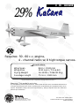
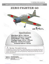
INSTRUCTION MANUAL
It is designed for maximum performance. Please seek advice if one is not familiar with this kind
of engine powered precision model. Operating this model without prior preparation may cause
injuries. Remember, safety is the most important thing. Always keep this instruction manual at
hand for quick reference.
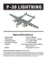
Wing Span
WingArea
Flying Weight
Fuselage Length
84 in / 2130 mm
1131 sq in / 73 sq dm
16-18 lbs / 7264-8172 g
75.5 in / 1920 mm
Warning ! This model is not a toy.
* Specifications are subject to change without notice.*
A
L
M
O
S
T
-
R
E
A
D
Y
-
T
O
-
F
L
Y
29%29%
Requires: 50 - 60 c.c. engine,
4 - channel radio w/ 8 high torque servos.
Specifications
FACTORY PRE-FABRICATED
ALMOST-READY-TO-FLY (ARF) SERIES
MADE IN CHINA
The World Models
Manufacturing Co., LTD.
www.theworldmodels.com

P. 1
INDEX
BEFOREYOU BEGIN
PARTS LIST
ASSEMBLY
SAFETY PRECAUTIONS
P. 1
P. 2
P.3- 12
P. 12
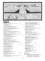
BEFORE YOU BEGIN
Do not overlook this symbol!
Cut off shaded portion.
Ensure smooth non-binding
movement while assembling.
Apply instant glue
(C.A.glue, super glue.)
Assemble left and right
sides the same way.
Peel off shaded portion
covering film.
Pay close attention here!
Apply epoxy glue.
Pierce the shaded portion
covering film.
Must be purchased separately!
Drill holes with the specified
diameter (here: 3mm).
3mm
Warning!
Apply thread locker
29%29%
Check all parts. If you find any defective or missing parts contact your local dealer . Please DRY FIT
and check for defects for all parts that will require CA or Epoxy for final assembly. Any parts you
find to be defective after the gluing process may be difficult to remove for warranty replacement. The
manufacturer will replace any defective parts, but will not extend to the parts that are good before
gluing to defective parts during assembly. Warranty will not cover any parts modified by customer.
Read through the manual before you begin, so you will have an overall idea of what to do.
Symbols used throughout this instruction manual comprise of the following : -
1
2
3

P. 2
TOUGHLONSTL550 PEARLBLUE
TOUGHLONSTL330 CADMIUMYELLOW
TOUGHLONSTL511 FERRARIRED
COVERING:
Parts List
1.MAIN WING -- 1 pair
METAL HINGES -- 16 pcs
2.HEAVY DUTY SERVO HORN PL4120300 -- 4 sets
SCREW PM4x75mm -- 2 pcs
SCREW PM4x65 -- 2 pcs
M4 NYLON INSERT LOCK NUT -- 4 pcs
HEAVY DUTY HORN BRACKET PL4112400 -- 4 pcs
HEAVY DUTY CLEVIS PL4112200 -- 8 sets
SWIVEL CLEVIS HORN FAIRING PL4610010 -- 4 sets
PUSHROD 2.5x57mm w/ Threads (For Aileron) -- 4 pcs
3.STABILIZER & ELEVATOR -- 1 set
METAL HINGES -- 10 pcs
PUSHROD 2.5x66mm w/ Threads (For Elevator) -- 2 pcs
HEAVY DUTY HORN BRACKET PL4112400 -- 2 pcs
HEAVY DUTY SERVO HORN PL4120300 -- 2 sets
HEAVY DUTY CLEVIS PL4112200 -- 4 sets
SWIVEL CLEVIS HORN FAIRING PL4610010 -- 2 sets
SCREW PM4x65mm -- 2 pcs
M4 NYLON INSERT LOCK NUT -- 2 pcs
WOOD 6x10x22mm (For Elevator Servo) -- 4 pcs
4.STABILIZER TUBE 16x403mm -- 1 pc.
SCREW PWA3x12mm -- 2 pcs
5.VERTICAL FIN & RUDDER -- 1 set
METAL HINGES -- 5 pcs
6.TAIL GEAR ASSEMBLY 13-22LBS PL3410021 -- 1 set
7.FIRE WALL 9x120x132.2mm (F12) -- 1 pc.
ENGINE BOX SIDE PLATE 5x97x266.5mm (F10) -- 1 pc.
ENGINE BOX SIDE PLATE 5x97x259.6mm (F11) -- 1 pc.
LOWER PLATE 3x126x131mm (F13) -- 1 pc.
BALSA7x7x97mm (F23) -- 1 pc.
BALSA7x7x97mm (F24) -- 1 pc.
BALSA7x7x121mm (F25) -- 1 pc.
BALSA7x7x97mm (F26) -- 2 pcs
BALSA7x7x78mm (F26D) -- 4 pcs
BALSA10x10x97mm(F23A)--1 pc.
BALSA10x10x97mm(F24A)--1 pc.
BALSA10x10x121mm(F2A)--1 pc.
8.MAIN LANDING GEAR -- 1 pc.
MAIN WHEEL 76mm -- 2 pcs
AXLE SHAFT 4.5x54mm -- 2 pcs
M8 NYLON INSERT LOCK NUT -- 2 pcs
SCREW PA3x14mm -- 4 pcs
SOCKET HEAD SCREW M5x16mm -- 4 pcs
COLLAR 4.6mm w/ set screw -- 4 pcs
WHEEL PANTS -- 1 pair
COPPER TUBE d2.5x3.2x8mm(For Rudder)--2 pcs
HEAVY DUTY CLEVIS PL4112200 -- 2 pcs
HEAVY DUTY HORN BRACKET PL4112400 -- 2 pcs
SWIVEL CLEVIS HORN FAIRING PL4610020 -- 1 set
SCREW M4x100mm -- 1 pc.
M4 NYLON INSERT LOCK NUT -- 2 pcs
SCREW PWA2.6x12mm -- 1 pc.
PLYWOOD 3x42.5x153.5mm -- 1 pc.
10.FUELTANK 650cc PL1111650G(Gasoline Fuel)--1 set
CABLE TIE (For Fuel Tank)--2 pcs
11.PLYWOOD 3x100x150mm--1 pc.
SCREW PWA2.6x12mm--4 pcs
M6 BLIND NUT --4 pcs
SOCKET HEAD SCREW M6x50mm--4 pcs
WASHER d6x15mm--4 pcs
12.EYE SCREW M2.5x8x35mm w/ Theads(For Rudder)--2 pcs
THROTTLE PUSHWIRE1.2x500mm--1 pc.
w/ Plastic Tube d2xD3x300mm--1 pc.
SPONGE --2 pcs
LINKAGE CONNECTOR 2.1mm--1 set
HEAVY DUTY SERVO HORN PL4120600--1 set
HEAVY DUTY CLEVIS PL4112200--2 pcs
COPPER TUBE d2.5x3.2x8mm(For Rudder)--2 pcs
13.WING TUBE 25.5x914mm--1 pc.
SCREW PM3x25mm--1 pc.
SCREW PA3x25mm--1 pc.
WASHER d3xD7mm--2 pcs
WING FAIRING--1 pair
14.COCKPIT--1 pc.
CANOPY--1 pc.
PILOT(PC001102B)--1 pc.
SCREW PWA2.3x12mm--6 pcs
SCREW PM3x20mm--2 pcs
SILICON GROMMET d1.5xD6.5mm--6 pcs
WASHER d3xD7mm--2 pcs
15.COWLING--1 pc.
SPINNER 89mm(w/ alu.back plate)--1 set
SCREW PA3x12mm--6 pcs
SILICON GROMMET d2.5xD8.5mm--6 pcs
WASHER d3xD7mm--6 pcs
16.DECALS--1 set
17.HAND TAP M4--1 pc.
9.EYE SCREW M2.5x8x35mm w/ Theads (For Rudder) -- 2 pcs
WIRE 1x900mm(For Rudder)--2 pcs

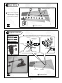
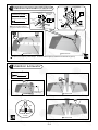
1Main Wing
Replace CA hinges by
metal hinges. Glue the
metal hinges to wing
and aileron by epoxy.
P.3
Aileron Servos
2
PM 2x12 mm
M2 Nut
PL4120300
2
M4 Nylon Insert Lock Nut
4
PM4x75mm Screw
2
PM4x65mm Screw
Locate hardwood blocks pre-installed in the ailerons.
Bottom View
Aileron Servo Lead
Bottom View
PM4x65mm PM4x75mm
1mm
M2Nut
PM2x8mm
HeavyDuty
Clevis
Pushrod
2.5x57mm PM4x75mm
M4 Nylon Insert
Lock Nut
PM2x8mm
M2 Nut
Heavy Duty
Clevis
Heavy Duty Horn
Bracket
PA1.7x8mm
3.7mm
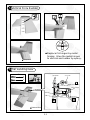
Drill and tap the swivel
clevis horn locations for
M4 machine screw.
M4 Tap
(PM4x65mm)

P.4
3Stabilizer & Elevator Pushrod
Replace CA hinges by metal hinges. Glue the metal hinges to stabilizer and elevator by epoxy.
PM4x65mm Screw
2
M4 Nylon Insert Lock Nut
2
1mm
Wooden
6x10x22mm
M2Nut
PM2x8mm
HeavyDuty
Clevis
Pushrod
Ø2.5x66mm
PM4x65mm
M4 Nylon Insert
Lock Nut
PM2x8mm
M2 Nut
Heavy Duty
Clevis
Heavy Duty Horn
Bracket
PA1.7x8mm
3.7mm
Drill and tap the swivel
clevis horn locations for
M4 machine screw.
M4 Tap
4Stabilizer & Elevator
Bottom View Bottom View
PWA3 x 12mm Screw
2
A=A
A
A
Bottom View
PWA3x12mm
2mm
Stabilizer Tube
16x403mm
¨
Bottom View
2mm
PWA3x12mm
Bottom View
PL4120300
Locate hardwood blocks
pre-installed in the elevator.
≈36mm
≈158mm

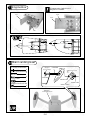
5Vertical Fin & Rudder
B B'
B=B'
Replace CAhinges by metal
hinges. Glue the metal hinges
to vertical and rudder by epoxy.
Tail Landing Gear
6
BottomView
P.5
Completed
M3 x 3mm Set Screw
M3 x 3mm
Set Screw
PWA2 x 12mm
3.1mm Collar
PA3 x14mm
1.5mm
1mm
PA3x14mm Screw
3
PWA2x12mm Screw
3

P.6
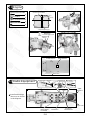
7Engine Box Please note right thrust
angle of firewall.
8Main Landing Gear
M5x16mm
Socket Head Screw
¨4.5x54mm Axle Shaft
2
PA3x14mm
Screw
4
M8 Nylon Inert Lock Nut
4.6mm Collar
4
M5x16mmSOCKET HEAD SCREW
4
2
¨4.5x54mm
Wheel 76mm
¨4.6mm Collar
4.6mm Collar
M8 Nylon
Inert Lock Nut
PA3x14mm
3mm Set Screw
Use epoxy to
glue all parts
together.
F11
F10
F25
F24
F12
F23
F26
F26
F26D
F26D
F13
32mm
3
F2D
F23A
F24A
F11
F10
F12
F13

Plywood 3x42.5x153.5mm
PWA2.6x12mm
1.5mm
P.7
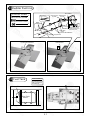
9Rudder Pushrod
10 Fuel Tank
Fuel Tank
650cc
Cable Tie
Tank installation
Tank is sitting on
high-density foam
with nylon ties to
hold to floor
1
M4 Nylon Insert Lock Nut
1
PM4x65mm Screw
PWA2.6x12mm Screw
1
Eye Screw M2.5x8x35mm
Copper Tube
Heavy Duty Horn
Bracket
M 4 x 100mm
PM2x8mm
M2Nut
M4 Nylon Insert
Lock Nut
Heavy Duty
Clevis
PA1.7x8mm
M4 Tap
3.7mm
Drill and tap the swivel
clevis horn locations for
M4 machine screw.
Press down the
center 1/ 3 portion
WIRE
Ø1x900mm

P.8
11 Engine
12 Radio Equipment
PWA2.6x12mm Screw
4
Install and arrange
the servo as shown
in the diagram.
M6 Blind Nut
M6x50mm
socket head screw
d6xD15mm
Washer
M6x50mmSOCKET HEAD SCREW
4
M6 Blind Nut
4
d6xD15mm Washer
4
Center line of firewall
9.5mm
Engine thrust line
F12
˜55mm
Plywood
3x100x150mm
PWA2.6x12mm
1.5mm
Bottom View
Copper Tube
PM2x8mm
Heavy Duty
Clevis
Eye Screw
M2 Nut
Rudder Servo
HEAVYDUTY
SERVOHORN
PL4120600
Eye Screw
M2.5x8x35mm
WIRE
1x900mm
Heavy Duty
Clevis
Front
Copper Tube
M2 Nut
PM2x12mm
PL4120600
Press down the
center 1/ 3 portion

P.9
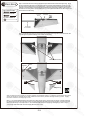
Main Wing
13
Step 1. Insertthe aluminumwing tube with thepre-drilled holeend into the right wing. Align
the lines marked atthe wing root and wing tube,then apply the PM3X25mm machine screw
through the pre-drilled holeon top of the wing. ( please confirm the alignmentof the hole by
putting a 2.5mm diameter rod through the pre-drilled wing hole before applying the screw )
The hole on the wing tube is pre-threaded, do not over tighten the PM3 screw, the set up is for
future removal of the wing.
d3 x D7mm
Washer
PM3x25mm
Screw
1
2
PA3x25mm
Screw
1
Step 2. Install the right wing to the fuselage by inserting the wing tube (now attached to the
right wing) through the fuselage, then install the left wing.
Lead toAileron Servo
PM3x25mm
d3 x D7mm
Washer
Wing Fairing
PA3x25mm
d3 x D7mm
Washer
Wing Tube
25.5x914mm
300mm
2.5mm
Step 3. Make sure the wings are resting against the fuselage tightly. Locate the pre-drilled 2.5mm hole
at top of left wing, and drill along with 2.5mm drill bit until it passes through the wing tube. Apply
the PA3 X25mm self-tapping screw.
Note : It is recommended that the wing tube stays with the left wing. Removal of the wings could be achieved
by removing the right wing machine screw, the right wing then the left wing with wing tube. If removal of wing
tube from left wing is also required, it is recommended that instead of applying self-tapping screw in step 3,
you pre-tap with M3 thread cutter and apply M3 machine screw.

P.10
14 Canopy
d3 x D7mm Washer
2
PWA2.3x12mm Screw
6
6
d1.5 x D6.5 mm
Silicon Grommet
PM3x20mm Screw
2
PM3x20mm
d3 x D7mm
Washer
Pilot
First insert the grommet to the canopy then apply screw.
3
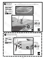
15
Cowling & Spinner
d3 x D7mm Washer
6
PA3x12mm Screw
6
6
d2.5 x D8.5 mm
Silicon Grommet
Spinner
89mm
¨
First insert the grommet to the cowling then apply screw.
1.5mm
d1.5xD6.5mm
Silicon Grommet
PWA2.3x12mm
1.5mm
d2.5xD8.5mm
Silicon Grommet
PA3x12mm
Decals
d3 x D7mm
Washer

P.11
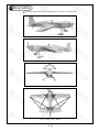
16 Wing Setting
A=A' B=B' C=C' D=D'
Adjust the wing and fuselage configuration as in the diagrams.shown
AA'
BB'
CC'
DD'

P.12
17 Control Throws
Important Safety Precautions
# First time flyer should never fly by himself / herself. Assistance from experienced flyer is
absolutely necessary.
# Pre-flight adjustment must be done before flying, it is very dangerous to fly a badly
pre-adjusted aircraft.
# is specially designed to be powered by gasoline engine, using a
more powerful engine does not mean better performance. In fact, over powered
engine may cause severe damage and injuries.
# Make sure the air field is spacious, never fly the plane too close to people and never get
too close to a running propeller.
# If you find wrinkles on the covering as a result of weather changes, you can use hot iron
to remove the wrinkles. Please begin with lower temperature setting and gradually raise
the temperature until the wrinkles are gone. Too hot an iron may damage the covering.
# Check and re-tighten up all factory assembled screws, use thread locker if applicable.
50-60cc
Adjust the control throws as shown in the diagram.
These throws are good for general flying. You can
adjust according to your personal preference.
18 C.G.
185mm
7.28 in.
C.G.
The ideal C.G. position is 185 behind
the leading edge measured at where the wing
meets the fuselage. In order to obtain the C.G.
specified, add weight to the fuselage or move
the battery position. Check the C.G. before
flying.
mm (7.28in.)
Elevator
Rudder
Ailerons
30mm
30mm
50mm
50mm
80mm
80mm
29%29%
A170SPO12920906

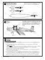
LINKAGE CONNECTOR
HW7111050 & HW7111060
Drill 2mm hole at servo horn. Insert linkage connector
into servo horn.
Make sure shoulder of
screw is cleared from
servo horn.
Add washer to reduce
play if necessary.
Shoulder
Tighten up the round nut
against the shoulder. Apply
CA or permanent thread
locker.
After fastening the round nut, make sure that
the linkage connector can rotate freely.
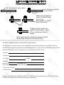
Product Registration Form (US Customers)
We would like to share with you any relevant information regarding your model, including
product news and free upgrade parts when applicable. Please fill in the following and send to
1.Name:
2.Address:
3.Phone #: e-mail:
4.Model:
Wing QC# Fuselage QC#
(QC numbers are stamped on wing and fuselage)
5.Date of Purchase:
6.Store Name:
Please call AirBorne Models at 925 371 0922 for any assistance in filling this form.
Thank you very much for purchasing our product.
Air orne Models, 4749-K, Bennett Drive, Livermore, CA 94551 USA.
B

A170SPO12920906
The World Models
Manufacturing Co., LTD.
www.theworldmodels.com
-
 1
1
-
 2
2
-
 3
3
-
 4
4
-
 5
5
-
 6
6
-
 7
7
-
 8
8
-
 9
9
-
 10
10
-
 11
11
-
 12
12
-
 13
13
-
 14
14
-
 15
15


Ask a question and I''ll find the answer in the document
Finding information in a document is now easier with AI
Other documents
-
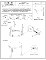 Riverside Furniture 73509 Assembly Instructions
-
 Nitroplanes P-38 LIGHTNING User manual
-
THE WORLD MODELS Pilatus PC-6 Porter 40 User manual
-
THE WORLD MODELS A321 User manual
-
 The Wings Maker ZERO FIGHTER 60 User manual
-
-
-
-
Black Horce Model A6M ZERO Instruction Manual Book
-
Seagull Models AT-6 TEXAN Assembly Manual


