Heatilator A42R Installation guide
- Category
- Fireplaces
- Type
- Installation guide

Heatilator•A36/42C,A36/42CH•InstallersManual•4017-262•RevD•10/07/13 1
Installationandserviceofthisreplaceshouldbe
performedbyqualiedpersonnel.Hearth&Home
TechnologiesrecommendsNFIcertiedprofes-
sionals,ortechnicianssupervisedbyan
NFIcertiedprofessional.
WOODBURNING FIREPLACE
Fire Risk.
WARNING
Forusewithsolidwoodfuelonly.
Otherfuelsmayoverreandgenerate
poisonousgases(i.e.carbonmonoxide).
Model(s):
Installation Manual
Installation and Fireplace Setup
WARNING
HOT SURFACES!
Glassandothersurfacesarehotduring
operationANDcooldown.
Hot glass will cause burns.
• DO NOTtouchglassuntilitiscooled
• NEVERallowchildrentotouchglass
• Keepchildrenaway
• CAREFULLY SUPERVISE children in same room as
replace.
• Alertchildrenandadultstohazardsofhightemperatures.
Hightemperaturesmayigniteclothingorotherammable
materials.
• Keep clothing, furniture, draperies and other ammable
materialsaway.
INSTALLER: Leave this manual with party responsible for use and operation.
OWNER: Retain this manual for future reference.
A36C, A36CH
A42C, A42CH
NOTICE: DO NOT discard this manual!
• DO NOTstoreorusegasolineorotheram-
mablevaporsandliquidsinthevicinityofthis
oranyotherappliance.
• DO NOToverre.Overringwillvoidyour
warranty.
• Complywithallminimumclearancestocom-
bustiblesasspecied.Failuretocomplymay
causehousere.
WARNING: If the information in these
instructionsisnotfollowedexactly,are
or explosion may result causing property
damage, personal injury, or death.

Heatilator • A36/42C, A36/42CH • Installers Manual • 4017-262 • Rev D • 10/07/13
2
Safety Alert Key:
• DANGER! Indicatesahazardoussituationwhich,ifnotavoidedwillresultindeathorseriousinjury.
• WARNING!Indicatesahazardoussituationwhich,ifnotavoidedcouldresultindeathorseriousinjury.
• CAUTION! Indicatesahazardoussituationwhich,ifnotavoided,couldresultinminorormoderateinjury.
• NOTICE:Indicatespracticeswhichmaycausedamagetothereplaceortoproperty.
Table of Contents
1 ProductSpecic&ImportantSafetyInformation
A.FireplaceCertication 4
B.Non-CombustibleMaterials 4
C.CombustibleMaterials 4
D.ElectricalCodes 4
2 Getting Started
A.TypicalFireplaceSystem 5
B.DesignandInstallationConsiderations 6
1.SelectingFireplaceLocations 6
2.LocatingFireplace&Chimney 7
C.ToolsandSuppliesNeeded 8
D.InspectFireplaceandComponents 8
E.FireplaceSystemRequirements 8
3 Framing and Clearances
A.FireplaceDimensions 9
B.Clearances 10
MinimumClearancestoCombustibles 10
C.ConstructtheChase 11
D.FrametheFireplace 12
E.SecureandLeveltheFireplace 12
F. ProtectiveMetalHearthStrips 13
G.FanKit(optional) 13
H.OutsideAirKit(optional) 14
4 Chimney and Termination Requirements
A.ChimneyRequirements 15
B.Offsets/Returns 16
C.TerminationRequirements 17
5 Chimney Installation
A.TypicalChimneySystem 18
B.AssembleChimneySections 19
C.SecureOffset/Return 20
D.InstallCeilingFirestops 20
E.InstallAtticInsulationShield 21
F. RoofPenetration 22
G.InstallChase/ChaseTop 22
H.TerminationCapRequirements 23
I. InstallTerminationCap 23
6 Shrouds
A.RadiationShield 25
B.FieldConstructedShrouds 25
1.OpenTopShroud 25
2.MailboxStyleShroud 26
3.RoofedStyleShroud 26
7 Finishing
A.FinishingMaterial 27
B.HearthExtension,BuildingandFinishing 28
1.FireplaceInstalledFlushontheFloor 29
2.RaisedHearthExtensionandRaisedFireplace 30
C.Non-CombustibleSealantMaterial 31
D.MantelandWallProjections 32
E.Sidewalls/Surrounds 33
8 Fireplace Setup
A.GasLog/LighterProvision 34
B.WoodBurningInserts 34
9 Reference Materials
A.ChimneyComponents 35
B.OptionalComponents 39
►

Heatilator • A36/42C, A36/42CH • Installers Manual • 4017-262 • Rev D • 10/07/13 3
Customer:
Lot/Address
Model (circle one): A36C A36CH
A42C A42CH
YES IF NO, WHY?
Wiringhasbeeninstalledifnecessary.
Dealer/Distributor Phone #
Serial #:
Roofflashinginstalled.
Terminationinstalled.
Fireplace Install
ATTENTION INSTALLER:
Follow this Standard Work Checklist
Thisstandardworkchecklististobeusedbytheinstallerinconjuctionwith,notinsteadof,theinstructionscontainedinthisinstallation
manual.
Date Installed:
Location of Fireplace:
Installer:
WARNING! Risk of Fire or Explosion! Failure to install fireplace acording to these instructions can lead to a fire or
explosion.
Verifiedthatthechaseisinsulatedandsealed.(Pg.11)
Verifiedclearancestocombustibles.(Pg.10)
Fireplaceisleveledandsecured.(Pg.12)
Hearthextensionsize/heightdecided.(Pg.28)
Chimneyconfigurationcomplieswithdiagrams.
Chimneyinstalled,lockedandsecuredinplacewithproperclearance.
Chimneyairkitinstalled.
Firestopsinstalled.
Protectivehearthstripsinstalledpermanualrequirements.(Pg.13)
Outsideairkitinstalled.(Pg14)
ChimneySection4&5(Pg.15)
Atticinsulationshieldinstalled.
Shrouds Section 6 (Pg. 25)
Shroudisinstalledproperlyperinstructions.
Commentscommunicatedtopartyresponsible
4017-264•RevA•3-18-13
•Photographingtheinstallationandcopyingthischecklistforyourfile.
Combustiblematerialsnotinstalledinnon-combustibleareas.
Allpackagingandprotectivematerialsremoved.
Optionaldoorsproperlyinstalled.
Refractoryinstalledcorrectly.
Grateisproperlyinstalled.
Firescreeninstalledproperly.
(Builder/Gen.Contractor)(Installer)(Date)
Comments:Furtherdescriptionoftheissues,whoisresponsible(Installer/Builder/OtherTrades,etc.)andcorrectiveactionneeded:
Manualbagandallofitscontentsareremovedfromthefireplaceandgiventotheparty
responsibleforuseandoperation.
•Thatthischecklistremainvisibleatalltimesonthefireplaceuntiltheinstallationiscomplete.
__________________________by______________________on_________
Hearthextensioninstalledpermanualrequirements.
Verifiedallclearancesmeetinstallationmanualrequirements.
Mantelsandwallprojectionscomplywithinstallationmanualrequirements.
Fireplace Setup Section 8 (Pg. 34)
Hearth&HomeTechnologiesrecommendsthefollowing:
Finishing Section 7 (Pg. 27)

Heatilator • A36/42C, A36/42CH • Installers Manual • 4017-262 • Rev D • 10/07/13
4
WARNING! Risk of Fire! Hearth & Home Technologies
disclaims any responsibility for, and the warranty and
agency listing will be voided by the following actions.
DO NOT:
• installoroperatedamagedreplace
• modifyreplace
• install other than as instructed by Hearth & Home
Technologies
• operate the fireplace without fully assembling all
components
• overre
• installunventedgaslogset
• installanycomponentnotapprovedbyHearth&Home
Technologies
• installpartsorcomponentsnotListedorapproved
Improper installation, adjustment, alteration, service or
maintenance can cause injury or property damage. For
assistance or additional information, consult a qualied
installer, service agency or your dealer.
B. Non-Combustible Materials
• Materialswhich willnot igniteand burn,composed of
anycombinationofthefollowing:
- Steel - Iron
- Brick - Tile
- Concrete - Slate
- Glass - Plasters
• MaterialsreportedaspassingASTM E 136, Standard
Test Method for Behavior of Metals, in a Vertical Tube
Furnace at 750° C
C. Combustible Materials
• Materialsmadeoforsurfacedwithanyofthefollowing
materials:
- Wood - Compressedpaper
- Plantbers - Plastic
- Plywood/OSB - Sheetrock(drywall)
• Anymaterialthatcanigniteandburn;ameproofedor
not,plasteredorun-plastered
1 ProductSpecic&ImportantSafetyInformation
A.FireplaceCertication
D. Electrical Codes
NOTICE: This replace must be electrically wired and
grounded in accordance with local codes or, in the
absence of local codes, with National Electric Code ANSI/
NFPA 70-latest edition or the Canadian Electric Code
CSA C22.1.
• A110-120VACcircuitforthisproductmustbeprotected
with ground-fault circuit-interrupter protection, in
compliancewiththeapplicableelectricalcodes,when
itisinstalledindamplocations.
ThisreplacemaybeinstalledinsleepingroomsEX-
CEPTinmanufacturedhomes.Ifinstalledwithagaslog
set,provisionsfortheNationalFuelGasCodemustbe
met.
Thisreplacehasbeentestedandlistedforusewith
theoptionalcomponentsspeciedinthismanual.These
optionalcomponentsmaybepurchasedseparatelyand
installedatalaterdate.Anoutsideairkit,gasinsert,gas
logsetorgaslog-lightershouldbeinstalledatthetimeof
replaceinstallation.
HeatilatorisaregisteredtrademarkofHearth&Home
Technologies.
Thisreplacesystemhasbeentestedandlistedinaccor-
dancewithUL127andULC-S610standardsbyUnder-
writersLaboratoriesInc.forinstallationandoperationin
theUnitedStatesandCanada.

Heatilator • A36/42C, A36/42CH • Installers Manual • 4017-262 • Rev D • 10/07/13 5
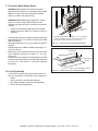
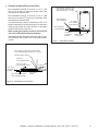
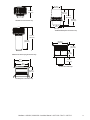
2 Getting Started
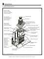
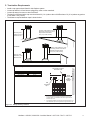
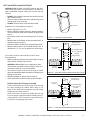
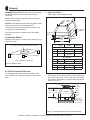
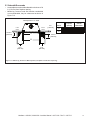
A. Typical Fireplace System
Figure 2.1 Typical Fireplace System
)
)
)
)
)
)
)
)
)
)
)
)
)
)
)
)
)
)
)
)
)
)
)
)
)
)
)
)
)
)
)
))
)
)
)
)
)
)
)
)
)
)
)
)
)
)
)
)
)
)
)
)
)
)
)
)
)
)
)
)
Non-combustible
roof flashing maintains
minimum clearance
around chimney
Additional lateral
support for chimney
above roof (or enclosed
in chase) if needed
Ceiling firestop
on floor of attic
Support straps
on rafter support
chimney (not shown)
Termination cap
Chimney penetrates roof
preferably without affecting
roof rafters
Offset & Return (with hanger straps)
Framing headed off
in ceiling joists
Enclosed space above
and around fireplace
Mantel and surround
Decorative facing
and trim
Hearth extension
Factory-built fireplace
Protective metal
hearth strip(s)
Outside
combustion air
Combustible framing/header
on top of V-shaped standoffs
Chimney system
Attic insulation shield (not shown)
must be used here to keep
insulation away from chimney
if attic is insulated
Storm Collar
Chimney Air Kit
(Section 8)
Required in
Canada. Outlet
must be no
less than 4 ft.
(1.22 m) off
ground level.

Heatilator • A36/42C, A36/42CH • Installers Manual • 4017-262 • Rev D • 10/07/13
6
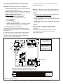
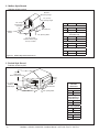
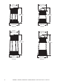
F
E
D
BC
Across a
corner
G
As a
room
divider
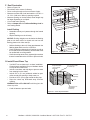
A
48 in.
(1219 mm)
minimum
B
Along a wall
B
A1/2 in. (13 mm) all
configurations
G
3/4 in. (19 mm) min. air
space from fireplace to
combustible materials. 1/2
in. (13 mm) allowed at
nailing flanges.
Note:
G
A*
In an exterior chase
or projecting into a
garage
B
Note: Measurements are FRAMING dimensions only and do
not include drywall either in the cavity or on the interior walls.
H
H
H
*8 in. (203 mm) extra space
included for outside air
connection. If outside air duct
has no bend, this dimension
may be reduced as long as
minimum clearances are met.
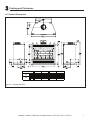
Model # A B C D E F G H
in. 51 43 74 7/8 35 3/4 15 3/4 53 23
mm 1295 1092 1902 908 400 1346 584
in. 57 49 77 1/2 38 7/8 18 54 7/8 23
mm 1448 1245 1969 987 457 1394 584
A36
A42
12 in. (305 mm)
Minimum from FP
opening to any
perpendicular wall.
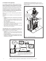
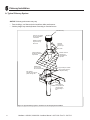
Figure 2.2 Fireplace Locations
NOTICE:
• Illustrationsandphotosreecttypicalinstallationsand
are FORDESIGNPURPOSESONLY.
• Illustrations/diagramsarenotdrawntoscale.
• Actualinstallation/appearancemayvaryduetoindividual
design preference.
• Hearth&HomeTechnologiesreservestherighttoalter
its products.
NOTICE: In addition to these framing dimensions, also
reference the following section: Clearances (Section 3).
NOTICE:
Aminimum3/4in.(19mm)airclearanceatthe
backandsidesofthereplaceassemblymustbe
maintained.
Chimney sections at any level require a 2 in. mini-
mum air space clearance between the framing
and chimney sections.
B. Design and Installation Considerations
NOTICE: Check building codes prior to installation.
• InstallationMUSTcomplywithlocal,regional,stateand
nationalcodesandregulations.
• Consultinsurancecarrier,localbuildinginspector,re
ofcialsorauthoritieshavingjurisdictionoverrestrictions,
installationinspectionandpermits.
• Before installing,determinethefollowing:
- Wherethereplaceistobeinstalled.
- Theventsystemcongurationtobeused.
- Gassupplypiping.
- Electricalwiring.
- Framingandnishingdetails.
- Whetheroptionalaccessories-devicessuchasa
fan,wallswitchorremotecontrol-aredesired.
1. Selecting Fireplace Locations
Thisreplacemaybeusedasaroomdivider,installed
alongawall,acrossacornerorusedinanexteriorchase.
SeeFigure2.2.
Locatingthereplaceinabasementshouldbeavoided.
Locatingnearfrequentlyopeneddoors,centralheat
outletsorreturns,orotherlocationsofconsiderableair
movementcanaffecttheperformance.
Considerationshouldbegiventothesefactorsbefore
decidingonalocation.

Heatilator • A36/42C, A36/42CH • Installers Manual • 4017-262 • Rev D • 10/07/13 7
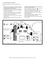
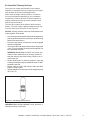
2. LocatingFireplace&Chimney
Locationofthereplaceandchimneywillaffectperfor-
mance.
• Installwithinthewarmairspaceenclosedbythebuilding
envelope.Thishelpstoproducemoredraft,especially
duringlightinganddie-downofthere.
• Installingthereplaceinabasementisnotrecommended.
• Penetratethehighestpartoftheroof.Thisminimizes
theeffectsofwindloading.
• Locate termination cap away from trees, adjacent
structures,unevenrooflinesandotherobstructions.
• Minimizetheuseofchimneyoffsets.
• Considerthereplacelocationrelativetooorandceiling
andatticjoists.
• Takeintoconsiderationtheterminationrequirementsin
Sections4and5.
Marginal Location:
• Below peak
Location NOT recommended:
• Not the highest point of the roof
• Wind loading possible
Multi-level Roofs
Windward
Leeward
Recommended Location:
• Above peak
Recommended:
• Insulated exterior chase
in cooler climates
Recommended Location:
• Above peak
• Inside heated space
Location NOT recommended:
• Too close to tree
• Below adjacent structure
• Lower roof line
• Avoid outside wall
Marginal Location:
• Wind loading possible
Figure 2.3 Recommended Chimney Locations
• Installtheoutsideairkitwiththeintakefacingprevailing
windsduringtheheatingseason.
• Ensure adequate outdoor air for all combustion
appliancesandexhaustequipment.
• Ensurefurnaceandairconditioningreturnventsarenot
locatedintheimmediatevicinityofthereplace.
• Avoidinstallingthereplaceneardoors,walkwaysor
smallisolatedspaces.
• Recessedlightingshouldbea“sealedcan”design.
• Attichatchesweatherstrippedorsealed.
• Atticmountedductworkandairhandlerjointsandseams
tapedorsealed.

Heatilator • A36/42C, A36/42CH • Installers Manual • 4017-262 • Rev D • 10/07/13
8
C. Tools and Supplies Needed
Beforebeginningtheinstallationbesurethefollowing
toolsandbuildingsuppliesareavailable:
Reciprocatingsaw Framingmaterial
Pliers Non-combustiblesealant
Hammer Gloves
Phillipsscrewdriver Framingsquare
Flatbladescrewdriver Electricdrillandbits
Plumbline Safetyglasses
Level Tapemeasure
1/2-3/4in.length,#6or#8self-drillingscrews
Misc.screwsandnails
D. Inspect Fireplace and Components
WARNING! Risk of Fire and/or Explosion! Damaged
parts could impair safe operation. DO NOT install dam-
aged,incompleteorsubstitutecomponents.Keepre-
place dry.
• Removereplaceandcomponentsfrompackagingand
inspectfordamage.
• Vent system components and doors are shipped in
separatepackages.
• Reporttoyourdealeranypartsdamagedinshipment.
• Read all the instructions before starting the
installation. Follow these instructions carefully
during the installation to ensure maximum safety
andbenet.
E. Fireplace System Requirements
TheHeatilatorreplacesystemrequirementsconsistof
thefollowing:
• Fireplace
- Refractory(includedwithreplace)
- Firescreen(includedwithreplace)
- Grate(includedwithreplace)
- HearthExtension(required,soldseparately)
• OutsideAirSystem(optional)
- AirInletHood
- Flex
• ChimneySystem
- AtticInsulationShield(includedwithreplace)
- Chimneyairkit(requiredinCanada,soldseparately)
- Chimneyterminationcap(required,soldseparately)
• Non-combustiblenishmaterial
• FK23FanKit(optional)
- JK9JunctionBox(includedwithreplace)
BC10FanSpeedMotorControl(optional)

Heatilator • A36/42C, A36/42CH • Installers Manual • 4017-262 • Rev D • 10/07/13 9
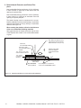
3 Framing and Clearances
A. Fireplace Dimensions
Figure 3.1 Fireplace Dimensions
Model # A B C D
in. 36 42 28 1/4 14 1/8
mm 914 1067 718 359
in. 42 48 30 7/8 15 1/2
mm 1067 1219 784 394
A36
A42

Heatilator • A36/42C, A36/42CH • Installers Manual • 4017-262 • Rev D • 10/07/13
10
B. Clearances
WARNING! Risk of Fire!
You must comply with all minimum air space clearances
tocombustiblesasspeciedinFigure3.2.DO NOT pack
required air spaces with insulation or other materials.
Framing or nishing material used on the front of, or in
frontof,thereplacecloserthantheminimumslistedmust
be constructed entirely of non-combustible materials (i.e.,
steel studs, concrete board, etc.). Failure to comply may
causere.
Figure 3.2 Clearances to Combustible Materials
Minimum Clearances to Combustibles
WITHIN ENCLOSURE AREA
Fireplacetobackwall 3/4in.(19mm)
Fireplacetosidewall 3/4in.(19mm)
Topstandoffstoheader 0in.(0mm)
Dooropeningtosidewall 12in.(305mm)
MANTEL
Mantelminimumheight 43-1/2in.(1105mm)
Maximummanteldepth 12in.(305mm)
(insulation)
0 in. to level
of standoffs
Attic
Insulation
Shield
(ceiling)
(roof)
(attic)
(ceiling)
Ceiling Firestop
Offset/Return (secured
with hanger straps)
Storm Collar
Roof Flashing
3/4 in. (19 mm) to back &
sides of appliance
(except at nailing flanges
where it is 1/2 in. [13 mm])
Must have 2 in. (51 mm)
minimum clearance
to header
0 in.
to floor
2 in. (51 mm) min.
Shaded areas
represent
2 in. (51 mm) min.
air space clearance
required around pipe
Combustible Object
48 in.
1219 mm
Adapter attached here
(not shown)

Heatilator • A36/42C, A36/42CH • Installers Manual • 4017-262 • Rev D • 10/07/13 11
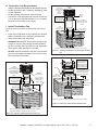
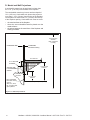
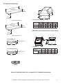
C. Construct the Chase
Achaseisaverticalboxlikestructurebuilttoenclosethe
replaceand/oritsventsystem.Verticalchimneysthat
runontheoutsideofabuildingmustbeinstalledinsidea
chase.
Incoldclimates,Hearth&HomeTechnologiesrecom-
mendsthatthechasebewellinsulatedusingbatttype
insulationbetweenthejoists.
Constructionofthechasemayvarywiththetypeofbuild-
ing.Theseinstructionsarenotsubstitutesfortherequire-
mentsoflocalbuildingcodes.LocalbuildingcodesMUST
bechecked.
Chasesshouldbeconstructedinthemannerofalloutside
wallsofthehometopreventcoldairdraftingproblems.
Thechaseshouldnotbreaktheoutsidebuildingenvelope
inanymanner.Allouterwallsneedtobeinsulated.
Buildingcodesrequirefalseceilingandceilingrestops/
atticshieldsateachoorofthechaseorevery10ft(3048
mm)ofclearspacetocontrolspreadofre.
Walls,ceiling,baseplateandcantileveroorattherst
levelofthechaseshouldbeinsulated(seeFigure3.3.)
Vaporandairinltrationbarriersshouldbeinstalledinthe
chaseasperregionalcodesfortherestofthehome.Ad-
ditionally,Hearth&HomeTechnologiesrecommendsthat
theinsidesurfacesbedrywalledandtaped(ortheuseof
anequivalentmethod)formaximumairtightness.
Holesandotheropeningsshouldbecaulkedwithhigh
temperaturecaulkorstuffedwithunfacedberglass
insulation.
Ceiling
Firestop
Metal Chase Top
Round Termination Cap
False Ceiling
Insulation in the
outside walls
of the chase
Attic
Insulation
Shield
Chimney
Ceiling
Firestop
Tabs
False Ceiling
False Ceiling
Insulation
Insulation
Storm Collar
Figure 3.3 Chase Assembly
1 2 3
All outside walls should be insulated.
Figure 3.4 Chase Constructions
1. Fireplaceandchimneyenclosedinanexteriorchase.
2. Chimneyoffsetthroughexteriorwallandenclosedinchase.
3. Chaseconstructedonroof.
• Thechaseisconstructedusingframingmaterialsmuch
thesameasthewallsinyourhome.Avarietyofsiding
materials may be used including brick, stone, veneer
brick,orstandardsidingmaterials.
• In constructing the chase, several factors must be
considered:
- Maintain a 2 in. (51 mm) air space around the
chimney.
- The chase top must be constructed of non-
combustiblematerial.
- Incoldclimates,arestopspacerandatticinsulation
shieldshouldbeinstalledinaninsulatedfalseceiling
at the 8 ft. (2438 mm) level above the replace
assembly.Thisreducesheatlossthroughthechase.
- Incold climates, the walls of the chase should be
insulatedtothelevelofthefalseceilingasshownin
Figure3.3.Thiswillhelpreduceheatlossfromthe
homearoundthereplace.
ThreeexamplesofchaseapplicationsareshowninFig-
ure3.4.
WARNING! You must install false ceilings and ceil-
ing restops at each oor of the chase or every 10 ft
(3.05 m) to control spread of re.
WARNING! Risk of Fire! DO NOT sealareabetweenre
stop opening and chimney pipe except where they enter
the attic or leave the warm air envelope of the home (use
600° F sealant).
WARNING! Risk of Fire! Youmustmaintain a minimum
2in.(51mm)airspaceclearancetoinsulationandother
materials surrounding the chimney system.
• Insulationandothermaterialsmustbermlysecuredto
prevent accidental contact with chimney system.
• Thechasemustbeproperlyblockedtopreventblown
insulation or other combustibles from entering and
makingcontactwithreplaceorchimney.
• Failuretopreventcontactbetweeninsulationorother
materials and chimney system may cause overheating
andre.

Heatilator • A36/42C, A36/42CH • Installers Manual • 4017-262 • Rev D • 10/07/13
12
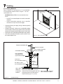
D. Frame the Fireplace
NOTICE: Hearth extension design must be determined
beforeinstallationofreplace.
Ifthereplaceisplacedontheoorthemaximumheight
ofanishedraisedhearthis2in.(51mm),ifyouwant
ahigherraisedhearththereplacemustbeplacedona
platform.
Thereplacewilltaframedopeningof:
A36:
41-1/2in.(1054mm)talland43in.(1092mm)wide,
A42:41-1/2in.(1054mm)talland49in.(1245mm)wide.
WARNING! Risk of Fire! Youmustcomplywithall
minimum air space clearances to combustibles. DO NOT
pack required air spaces with insulation or other materi-
als.
WARNING! Risk of Fire! Comply with all minimum clear-
ancesspecied.
• A minimum 3/4 in. (19 mm) air clearance must be
maintainedatthebackand3/4in.(19mm)tothesides
ofthereplaceassembly.
• Chimneysectionsatanylevelrequirea2in.(51mm)
minimum air space clearance between the framing and
chimney section.
Figure3.5showsatypicalframing(using2x4lumber)
ofthereplace,assumingcombustiblematerialsare
used.Allrequiredclearancestocombustiblesaroundthe
replacemustbeadheredto.SeeFigure3.2.Anyframing
acrossthetopofthereplacemustbeabovethelevelof
thetopstandoffs.(Norecessabovestandoffs.)
CAUTION! RiskofCuts/Abrasions.Wearprotectivegloves
and safety glasses during installation. Sheet metal edges
are sharp.
WARNING! Risk of Fire! Prevent contact with sagging,
loose insulation.
• DO NOT install against vapor barriers or exposed
insulation.
• Secureinsulationandvaporbarriers.
• Provideminimumairspaceclearancesatthesidesand
backofthereplaceassembly.
E. Secure and Level the Fireplace
Thisreplacemaybeplacedoneitheracombustibleor
noncombustiblecontinuousatsurface.Followthein-
structionsforframinginSection3.Slidethereplaceinto
position.Besuretoprovidetheminimum3/4in.airclear-
anceatthesidesand3/4in.atthebackofthereplace.
Thereplaceshouldbepositionedsothefaceofthenon-
combustiblematerialonthereplacewillbeushwiththe
faceofthedrywallonthewalls.
Levelthereplaceandshimasnecessary.
Figure 3.5 Framing the Fireplace
B
C
A
2 in. (51 mm)
min. air space
clearance
from chimney.
Header MUST NOT be notched!
D
D = extra space needed for outside air connection.
If outside air duct has no bend, this dimension may be
reduced as long as minimum clearances are met.
A B* C** D
in. 43 23 41 1/2 8
mm 1092 584 1054 203
in. 49 23 41 1/2 8
mm 1245 584 1054 203
** Adjust header height for a raised floor under fireplace.
Model #
A36
A42
* If interior of chase will be drywalled, add the thickness to
this measurement.
The
nished cavity depth must be no less than 23 in.
(584mm)fromthenishedbackwalltotheoutsideoffront
wallframing.Framingmustextendstraightupalltheway
totheceiling.
1/2 in.
(13 mm)
Fireplace must be set out
1/2 in. (13 mm) in front of
the face of the framing
material.

Heatilator • A36/42C, A36/42CH • Installers Manual • 4017-262 • Rev D • 10/07/13 13
Protective metal strips are placed 2 in. (51 mm) under the
front of the fireplace and must extend beyond the front
and sides of fireplace opening by 2 in. (51 mm).
1 in. (25 mm)
overlap
Raised Platform
Floor
2 in.
(51 mm)
1 in. (25 mm) min.
overlap
2 in.
(51 mm)
T
op p
i
ece must over
l
ap
bottom piece
Nail or screw metal strips in place.
Figure 3.7 Protect the Front of an Elevated Platform
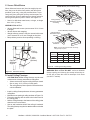
F. Protective Metal Hearth Strips
Figure 3.6 Position the Protective Metal Hearth Strips
• Locatethetwoprotectivemetalhearthstripsmeasuring
approximately26in.x4in.(660mmx102mm)included
withthisreplace.
• Slideeachmetalstrip2in.(51mm)underfrontedgeof
replace.
• Overlapstripsinthemiddleofreplaceopeningby1in.
(25mm)minimum.
• Metal strips must extend beyond the front and sides
of the replace opening by at least 2 in. (51 mm),
Figure3.6).
• Protectthefrontofaplatformelevatedabovethehearth
extensionwithmetalstrips(notincludedwithreplace)
per Figure 3.6. See Section 7 for hearth extension
instructions.
WARNING! Risk of Fire! Protective metal hearth
strips MUST be installed on combustible surfaces. DO
NOT cover metal strips with combustible materials.
Sparksorembersmayigniteooring.
WARNING! Risk of re! High temperatures, sparks,
embers or other burning material falling from the
replacemayigniteooringorconcealedcombustible
surfaces.
• ProtectivemetalhearthstripsMUSTbeinstalled.
• Hearth extensions MUST be installed exactly as
specied.
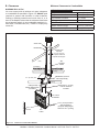
G. Fan Kit (optional)
Ifafanwillbeinstalled,thewiringmustbedonenow.
Use the instructions included with the accessories to
install:
• JK9JunctionBox(includedwithreplace)
• BC10MotorSpeedControlKit(soldseparately)
• FK23FanKit(soldseparately)

Heatilator • A36/42C, A36/42CH • Installers Manual • 4017-262 • Rev D • 10/07/13
14
H. Outside Air Kit (optional)
Ifyouinstallanoutsideairkit,Hearth&HomeTechnolo-
giesrecommendsyouutilizetheshortestductruntoop-
timizetheperformanceoftheoutsideairkit.Theoutside
airkitinlethoodshouldbepositionedinamannerthat
willnotallowsnow,leaves,etc.toblocktheinlet.Insome
installationstheairductmayneedtoberunvertically.
Insuchaninstallation,a3ft(914mm)heightdifference
mustbemaintainedfromthetopoftheuppermostchim-
neysectiontotheoutsideairinlethood.
RefertoFigures3.8and3.9whenplacingtheoutsideair
inlethood.
Theoutsideairkitisinstalledonthelefthandsideofthe
replace.
• Cuta4in.(102mm)holeinoutsidewalltoaccommodate
airpiping.
• Use4in.(102mm)ex(notsupplied)todirectlyconnect
outsideairtoreplaceintake.Insulatethepipetoprevent
frostcondensation.
• Usethesuppliedterminationcap.
• Seal between the wall and the pipe with silicone to
preventmoisturepenetrationandairleaks.
• Sealbetweentheterminationcapandthehousewith
siliconetopreventairinltration.
CAUTION! Risk of Cuts/Abrasions. Wearprotective
gloves and safety glasses during installation. Sheet metal
edges are sharp.
CAUTION! Risk of Fire or Asphyxiation! DO NOT draw
outsidecombustionairfromwall,oororceilingcavity,or
enclosed spaces such as an attic or garage.
• DO NOT place outside air hood close to exhaust vents or
chimneys. Fumes or odor could be drawn into the room
throughthereplace.
• Locateoutsideairinlettopreventblockagefromleaves,
snow/ice, or other debris. Blockages could cause
combustion air starvation. Figure 3.8 Outside Air Inlet Locations
Outlet placed
higher than 3 ft
below the
termination cap
Attic space
Garage or
combustible
liquids storage
Outlet blocked by
snow, leaves, etc.
Clear area
outside
house or in
ventilated
crawl space
YES
NO
NO
NO
NO
Factory-built
fireplace
• Use UL181 Class 0 or Class 1 rigid or flexible ducting.
• Install with short run or mainly straight duct, except small
dip for cold air trap which will help prevent flow of cold air.
• Secure flex duct with metal tape, screws or wire ties.
Figure 3.9 Outside Air Installation
)
)
)
)
)
)
)
)
)
)
)
)
)
)
)
)
)
)
)
)
)
)
)
)
)
)
)
)
)
)
)
)
)
)
)
)
)
)
)
)))
)
))
)
)
)
))))
)
))
))
)))
)
)
))
))
))
)
))
)
))
)))
))
)
)
)
)
))
)
)
)
)
)
)
)
)
)
)
)
)
3 ft min. from
top of uppermost
chimney section
to air inlet.

Heatilator • A36/42C, A36/42CH • Installers Manual • 4017-262 • Rev D • 10/07/13 15
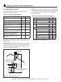
6 ft (1.83 m) max.
unsupported chimney
above roof
20 ft (6.10 m) max.
pipe between an
offset & return
35 ft (10.7 m)
max. straight
unsupported
chimney height
16.5 ft (5.03 m) min. height/single offset-return
20 ft. (6.10 m) min. height/double offset-return
90 ft (27.4 m) max. height
41-3/8 in.
(1051 mm)
Effective
Height
Ceiling firestop
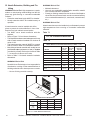
Figure 4.1 Chimney Requirements
NOTICE: Amaximumoftwopairsofoffsetsandreturns
may be used.
Minimum overall straight height 16.5ft 5.03 m
Minimumheightwithsingleoffset/
return
16.5ft 45.03m
Doubleoffset/returnminimumheight 20 ft 6.1m
Maximum height 90ft 27.43m
Maximum chimney length between an
offset and return
20 ft 6.1m
Maximum distance between chimney
stabilizers
35 ft 10.67m
Maximum unsupported chimney
length between the offset and return
6 ft 1.83m
Maximum unsupported chimney
heightabovethereplace
35 ft 10.67m
Maximum unsupported chimney
above roof
6 ft 1.83m
WARNING! Risk of Fire! Youmustmaintain2in.(51mm)
air space clearance to insulation and other combustible
materials around the chimney system. Failure to do so
maycauseoverheatingandre.
NOTICE: You must provide support for the pipe during
construction and check to be sure inadvertent loading has
notdislodgedthechimneysectionfromthereplaceorat
any chimney joint.
A. Chimney Requirements
Verticaldistancesaremeasuredfromthebaseofthe
replaceasshowninFigure4.1.
4 Chimney and Termination Requirements
Table 4.2 Chimney Component Dimensions
Table 4.1 Chimney Requirements
HEIGHT OF CHIMNEY COMPONENTS in. mm
Chimney Stabilizer
SL3 4-3/4 121
Offsets/Returns
SL315 13-3/8 340
SL330 15-1/2 394
Chimney Sections*
SL306 4-3/4 121
SL312 10-3/4 273
SL318 16-3/4 425
SL324 22-3/4 578
SL336 34-3/4 883
SL348 46-3/4 1187
*Dimensionsreecteffectiveheight.

Heatilator • A36/42C, A36/42CH • Installers Manual • 4017-262 • Rev D • 10/07/13
16
B. Offsets/Returns
• Useanoffset/returntobypassoverheadobstructions.
• Anoffsetandreturncanbeusedasasingleentityorseparatedbychimneysection(s).
WARNING! Risk of Fire! DO NOT useoffset/returnsgreaterthan30°.Chimneydraftwillberestrictedandcouldcause
overheatingandre.Secureoffsetswithscrews(nottoexceed1/2”/13mminlength)Securereturnswithstrapping.
Straight chimney sections may be secured with screws. Keep chimney sections from separating or twisting.
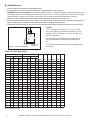
• Measuretheshiftneededtoavoidtheoverheadobstruction.RefertodimensionAinFigure4.2.
• FindtheappropriateAdimensionlistedinTable4.3.TheBdimensioncoincidingwiththeAdimensionmeasurementin
Table4.3representstherequiredverticalclearanceneededtocompletetheoffset/return.
• Readacrossthecharttondthenumberofchimneysections/modelnumbersneededbetweentheoffsetandreturn.
A
B
1-1/4 in. (32 mm)
OVERLAP
Figure 4.2 Chimney Offset/Return
Table 4.3 Offset Dimensions
Example:
Your“A”dimensionfromFigure8.3is141/2in.(368
mm).UsingTable8.2thedimensionclosestto,butnot
lessthan141/2in.(368mm)is141/2in.(368mm)us-
inga30°offset/return.
Youdeterminefromthetablethatyouneed341/8in.
(867mm)(Dimension“B”)betweentheoffsetandre-
turn.
Thechimneycomponentthatbesttsyourapplicationis
oneSL324.
15-degree 30-degree
SL306 SL312 SL318 SL324 SL336 SL348
A B A B
in. mm in. mm in. mm in. mm
15/8 41 133/8 340 35/8 92 151/2 394 - - - - - -
27/8 73 173/4 451 51/2 140 185/8 473 1 - - - - -
41/8 102 223/8 568 71/4 184 213/4 552 2 - - - - -
41/2 114 235/8 600 81/2 216 233/4 603 - 1 - - - -
53/4 146 281/4 718 101/4 260 27 686 1 1 - - - -
6 152 293/8 746 111/2 292 29 737 - - 1 - - -
71/4 184 34 864 131/4 337 321/8 816 - 2 - - - -
73/4 197 361/8 918 141/2 368 341/8 867 - - - 1 - -
83/4 222 393/4 1010 161/4 413 373/8 949 1 - - 1 - -
103/8 264 455/8 1159 191/4 489 421/2 1080 - - 2 - - -
105/8 270 463/4 1187 201/2 521 445/8 1133 - - - - 1 -
117/8 302 513/8 1305 221/4 565 473/4 1213 1 - - - 1 -
131/2 243 571/4 1454 251/4 641 527/8 1343 - - - 2 - -
133/4 349 583/8 1483 261/2 673 55 1397 - - - - - 1
15 381 63 1600 281/4 718 581/8 1476 1 - - - - 1
161/2 419 683/4 1746 311/4 794 631/4 1607 - 1 - - - 1
18 457 745/8 1895 341/4 870 681/2 1740 - - 1 - - 1
195/8 498 803/8 2042 371/4 946 733/4 1873 - - - 1 - 1
205/8 524 841/8 2137 391/8 994 767/8 1953 1 - - 1 - 1
223/4 578 917/8 2334 431/4 1099 841/8 2137 - - - - 1 1
24 610 961/2 2451 451/8 1146 871/4 2216 1 - - - 1 1
257/8 657 1031/2 2629 491/4 1251 941/2 2400 - - - - - 2
Properassemblyofair-cooledchimneypartsresultinanoverlapatchimneyjointsof1-1/4in.(32mm).Effective
lengthisbuiltintothischart.

Heatilator • A36/42C, A36/42CH • Installers Manual • 4017-262 • Rev D • 10/07/13 17
Slanted Roofs
Flat Roofs
Chimney must
extend 3 ft (.9 m)
above the roof
Chimney must extend 2 ft (.6 m)
above any portion of the roof or
adjacent structures within
10 ft (3 m) of the chimney
Chimney must
extend 3 ft (.9 m)
above the roof
Chimney must extend 2 ft (.6 m)
above any portion of the roof or
adjacent structures within
10 ft (3 m) of the chimney
Multiple Chimney Locations
A B
6 in. (minimum) up to 20 in.
152 mm/508 mm
18 in. minimum
457 mm
20 in. and over 0 in. minimum
Gas, Wood or Fuel Oil
Termination Cap
Wood
Minimum
(See
illustration
above)
B
Gas
Termination
Cap **
A *
Perpendicular Wall
*
If using decorative cap cover(s), this distance may need to be
increased. Refer to the installation instructions supplied with the
decorative cap cover.
**
In a staggered installation with both gas and wood terminations, the
wood termination cap must be higher than the gas termination cap.
Figure 4.3 Multiple Chimney Locations
C. Termination Requirements
• Installacapapprovedandlistedforthisreplacesystem.
• Locatecapwhereitwillnotbecomepluggedbysnoworothermaterials.
• Locatecapawayfromtreesorotherstructures.
• Thebottomoftheterminationcapmustbeatleast3ft(.91m)abovetheroofANDatleast2ft(.61m)aboveanyportion
ofroofwithin10ft(3.05m).
• Thedistancerequiredbetweencapsisshownbelow.

Heatilator • A36/42C, A36/42CH • Installers Manual • 4017-262 • Rev D • 10/07/13
18
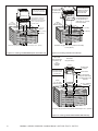
5 Chimney Installation
Termination Cap
Additional
support for
tall chimneys
Storm Collar
Maintain minimum
clearances to
combustibles as
specified
Chimney must extend
beyond combustible
roof structure
Maintain minimum
height of chimney
above roof
Install roof flashing
according to minimum
requirements
Offsets/returns
may not exceed
30° from vertical Support straps for offsets/
returns must be secured
to adequate framing
Ceiling firestops
are required where
chimney passes
through ceiling or
floor
Attic Shield is
required where chimney
passes through attic
Figure 5.1 Typical Chimney System - Guidelines for Chimney System Installation
NOTICE: Chimney performance may vary.
• Trees,buildings,rooflinesandwindconditionsaffectperformance.
• Chimneyheightmayneedadjustmentifsmokingoroverdraftoccurs.
A. Typical Chimney System

Heatilator • A36/42C, A36/42CH • Installers Manual • 4017-262 • Rev D • 10/07/13 19
NOTICE: Chimney sections cannot be disassembled once
locked together. Plan ahead!
• Lockchimneysectionsand/oroffsets/returnstogetherby
pushingdownwarduntilthetopsectionmeetsthestop
beadonthelowersection.
• Pullonthetopsectiontomakesureitisfullyengaged
andwillnotseparate.
• Youmayuse#6or#8sheetmetalscrewsnolongerthan
1/2in.(13mm)tofastenchimneysectionstogether.Do
NOTpenetrateinnerue.
WARNING! Risk of Fire! YouMUSTusescrews(pro-
vided)tofastenoffset/returnstochimneysectionsto
keep the chimney parts from twisting. Failure to do so
couldcausere.
• Fasten offset/returns to chimney sections. Insert the
screws(provided)throughthepredrilledholes.DoNOT
penetrateinnerue.
• Secure chimney returns with hanger straps provided;
fastentostudsorjoists.
• Verticalstraightrunsofchimneymustbesupportedevery
35ft(10.7m).
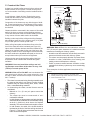
B. Assemble Chimney Sections
Useonlythosecomponentsdescribedinthismanual.
Substituteordamagedchimneycomponentscouldimpair
safeoperationandcauseoverheatingandre.
Attacheitherastraightchimneysectionoranoffsetto
thetopofthereplace(dependingonyourinstallation
requirement).Chimneysectionsarelockedtogetherby
pushingdownwarduntilthetopsectionmeetsthestop
beadonthelowersection.
Theinnerueisplacedtotheinsideoftheuesection
belowit.Theoutercasingisplacedoutsidetheoutercas-
ingofthechimneysectionbelowit.SeeFigure5.2.
WARNING! Risk of Fire! DO NOT install substitute or
damaged chimney components.
Figure 5.2 Assembling Chimney Sections

Heatilator • A36/42C, A36/42CH • Installers Manual • 4017-262 • Rev D • 10/07/13
20
C. Secure Offset/Return
D. Install Ceiling Firestops
CAUTION! Risk of Fire! Ceilingrestopsmustbeused
wheneverthechimneypenetratesaceiling/oor.
• Chaseconstructionrequiresceilingrestopsateach
oororevery10ft.(3.05m)ofclearspace.
• Theceilingrestopslowsspreadofreandreduces
coldairinltration.
• Installaceilingrestopwheneverchimneypenetrates
ceiling/oor.
• MarkandcutanopeninginceilingasshowninFigure5.4.
• Frametheopeningwiththesamesizelumberusedin
theceilingjoists.
• Nailtheceilingrestoptothebottomoftheceilingjoists
whenthereisaroomabove.
• Useanatticinsulationshieldiftheceilingisinsulated.
Theceilingrestopmaythenbeattachedaboveorbelow
thejoists.
ROOM ABOVE (non-insulated ceiling)
ATTIC ABOVE (insulated ceiling)
B
A
Ceilng firestop
attached to bottom
of framing
Ceiling firestop
attached to top of
framing
Note: Use same dimensional lumber for framing
ceiling firestop and joists.
2 in. (51mm)
clearance
2 in. (51mm)
clearance
WARNING! Risk of Fire! DO NOT seal area between
restopopeningandchimneypipeexceptwheretheyen-
ter the attic or leave the warm air envelope of the home
(use 600° F sealant).
Figure 5.4 Installing the Ceiling Firestop
Whenoffsetsandreturnsarejoinedtostraightpipesec-
tions,theymustbelockedintopositionwiththescrews
provided*(outeronly),usingthepredrilledholes.Topre-
ventgravityfrompullingthechimneysectionsapart,the
returnsandthechimneystabilizershavehangerstrapsfor
securingthesepartstojoistsorrafters.SeeFigure5.3.
* Use#6or#8sheetmetalscrew,orlarger,nolonger
than1/2in.(13mm).
WARNING! Risk of Fire!
• Secureoffsetswithscrews(nottoexceed1/2in./13mm
In length).
• Securereturnswithstrapping.
• Straightchimneysectionsmaybesecuredwithscrew
(nottoexceed1/2in./13mmInlength)atthejoints.
• Keepchimneysectionsfromseparatingortwisting.
Ceiling
Firestop
Straps
Optional
A
dditional
Support
Joint
Band
(Optional)
Figure 5.3 Secure the Chimney
Catalog #
A B
in. mm in. mm
FS338 14-1/2 368 14-1/2 368
FS339 14-1/2 368 18-3/8 467
FS340 14-1/2 368 23 584
Page is loading ...
Page is loading ...
Page is loading ...
Page is loading ...
Page is loading ...
Page is loading ...
Page is loading ...
Page is loading ...
Page is loading ...
Page is loading ...
Page is loading ...
Page is loading ...
Page is loading ...
Page is loading ...
Page is loading ...
Page is loading ...
Page is loading ...
Page is loading ...
Page is loading ...
Page is loading ...
-
 1
1
-
 2
2
-
 3
3
-
 4
4
-
 5
5
-
 6
6
-
 7
7
-
 8
8
-
 9
9
-
 10
10
-
 11
11
-
 12
12
-
 13
13
-
 14
14
-
 15
15
-
 16
16
-
 17
17
-
 18
18
-
 19
19
-
 20
20
-
 21
21
-
 22
22
-
 23
23
-
 24
24
-
 25
25
-
 26
26
-
 27
27
-
 28
28
-
 29
29
-
 30
30
-
 31
31
-
 32
32
-
 33
33
-
 34
34
-
 35
35
-
 36
36
-
 37
37
-
 38
38
-
 39
39
-
 40
40


Heatilator A42R Installation guide
- Category
- Fireplaces
- Type
- Installation guide
Ask a question and I''ll find the answer in the document
Finding information in a document is now easier with AI
Related papers
-
Heatilator A36 Architect Guide
-
-
-
-
-
-
-
-
-
Other documents
-
 Telbix STOW Operating instructions
-
Heat & Glo Longmire 42 Install Manual
-
Majestic Designer Series Wood-Burning Fireplace Installation guide
-
-
-
-
-
-
-
Lennox Hearth Products Merit HCI-36 User manual
