
,-I
<=
rr"
I-
Z
@
M/
"0
&
Eo
0
0")
f-
=m
"0
m
>
,,Q
a
E
14")
CO0
DEWALT Industrial Tool Co., 701 Joppa Road, Baltimore, MD 21286
(AUG09) Part No. N039242 DW718 Copyright © 2005, 2007, 2009 DEWALT
The following are trademarks for one or more DEWALT power tools: the yellow and black color scheme;
the "D" shaped air intake grill; the array of pyramids on the handgrip; the kit box configuration; and
the array of lozenge-shaped humps on the surface of the tool.
Definitions: Safety Guidelines
The definitions below describe the level of severity for each signal word. Please read the
manual and pay attention to these symbols.
A DANGER: Indicates an imminently hazardous situation which, if not avoided, will result
in death or serious injury.
_, WARNING: Indicates apotentially hazardous situation which, if not avoided, could result
in death or serious injury.
,&CAUTION: Indicates a potentially hazardous situation which, if not avoided, may result
in minor or moderate injury.
NOTICE: Indicates a practice not related to personal injury which, if not avoided, may
result in property damage.
IF YOU HAVE ANY QUESTIONS OR COMMENTS ABOUT THIS OR ANY DEWALT TOOL, CALL
US TOLL FREE AT: 1-800-4-DEWALT (1-800-433-9258)
IMPORTANT SAFETY INSTRUCTIONS
_ WARNING: Read all instructions before operating product. Failure to follow
all.instructions listed below may result in electric shock, fire and/or serious
injury.
READ ALL INSTRUCTIONS
Double Insulation
Double insulated tools are constructed throughout with two separate layers of electrical
insulation or one double thickness of insulation between you and the tool's electrical system.
Tools built with this insulation system are not intended to be grounded. As a result, your tool is
equipped with a two prong plug which permits you to use extension cords without concern for
maintaining a ground connection.
NOTE: Double insulation does not take the place of normal safety precautions when operating
this tool. The insulation system is for added protection against injury resulting from a possible
electrical insulation failure within the tool.
,&CAUTION." WHEN SERVICING USE ONLY IDENTICAL REPLACEMENT PARTS. Repair or
replace damaged cords.
Polarized Plugs
Polarized plugs (one blade is wider than the other) are used on equipment to reduce the risk of
electric shock. When provided, this plug will fit in the polarized outlet only one way. If the plug
does not fit fully in the outlet, reverse the plug. If it still does not fit, contact aqualified electrician
to install the proper outlet. Do not change the plug in any way.
Safety Instructions For All Tools
This miter saw accepts the DEWALT worklight and laser attachments.
_,WARNING: To reduce the risk of eye injury, ALWAYS use eye protection when operating
the miter saw.
• KEEP GUARD IN PLACE and in working order.
• REMOVE ADJUSTING KEYS AND WRENCHES. Form habit of checking to see that keys
and adjusting wrenches are removed from spindle before turning tool on. Tools, scrap
pieces, and other debris can be thrown at high speed, causing injury.
• KEEP WORK AREA CLEAN. Cluttered areas and benches invite accidents.
• DO NOT USE THE MACHINE IN A DANGEROUS ENVIRONMENT. The use of powertools
in damp or wet locations or in rain can cause shock or electrocution. Keep your work area
weft-fit to avoid tripping or placing arms, hands, and fingers in danger.
• KEEP CHILDRENAWAY. Aft visitors should be kept at a safe distance from work area. Your
shop is a potentially dangerous environment.
• MAKE WORKSHOP CHILDPROOF with padlocks, master switches, or by removing starter
keys. The unauthorized start-up of a machine by a child or visitor may result in injury.
• DON'T FORCE TOOL. It will do the job better and be safer at the rate for which it was
designed.
• USE RIGHT TOOL. Don't force tool or attachment to do ajob for which it was not designed.
Using the incorrect tool or attachment may result in personal injury.
• WEAR PROPER APPAREL. No loose clothing, gloves, neckties, rings, bracelets, or other
jewelry to get caught in moving parts. Non-slip footwear is recommended. Wear protective
hair covering to contain long hair. Air vents may cover moving parts and should also be
avoided.
• ALWAYS USE SAFETY GLASSES. Everyday eyeglasses are NOT safety glasses. Also
use face or dust mask if cutting operation is dusty. ALWAYS WEAR CERTIFIED SAFETY
EQUIPMENT:
• ANSI Z87.1 eye protection (CAN/CSA Z94.3)
• ANSI $12.6 ($3.19) hearing protection
• NIOSH/OSHA/MSHA respiratory protection
• SECURE THE WORKPIECE. Use clamps or a vise to hold the workpiece on the table
and against the fence or when your hand will be dangerously close to the blade within 6"
(152 mm). It is safer than using your hand and it frees both hands to operate tool.
• DON'T OVERREACH. Keep proper footing and balance at aft times. Loss of balance may
cause personal injury.
• MAINTAIN TOOLS WITH CARE. Keep tools sharp and clean forbestandsafestperformance.
Follow instructions for lubricating and changing accessories. Poorly maintained tools and
machines can further damage the tool or machine and/or cause injury.
TURN THE MACHINE "OFF" AND DISCONNECT THE MACHINE FROM THE POWER
SOURCE before installing or removing accessories, before adjusting or changing set-ups,
when making repairs or changing locations. An accidental start-up can cause injury. Do not
touch the plug's metal prongs when unplugging or plugging in the cord.
REDUCE THE RISK OF UNINTENTIONAL STARTING. Make sure that the switch is in the
"OFF" position before plugging in the power cord.
USE PROPER EXTENSION CORD. Make sure your extension cord is in good condition. If
your product is equipped with a cordset, use only 3-wire extension cords that have 3-prong
grounding-type plugs and 3-pole receptacles that accept the tool's plug. When using an
extension cord, be sure to use one heavy enough to carry the current your product will
draw. An undersized cord will cause a drop in line voltage resulting in loss of power and
overheating. The following table shows the correct size to use depending on cord length
and nameplate ampere rating. If in doubt, use the next heavier gage. The smaller the gage
number, the heavier the cord.
Minimum Gauge for Cord Sets
Volts Total Length of Cord in Feet (meters)
Ampere Rating 120V 25 (7.6) 50 (15.2) 100 (30.5) 150 (45.7)
240V 50 (15.2) 100 (30.5) 200 (61.0) 300 (91.4)
AWGMore
Than
0
6
10
12
Not More
Than
6
10
12
16
18 16 16 14
18 16 14 12
16 16 14 12
14 12 Not Recommended
• CHECK for DAMAGED PARTS. Before further use of the tool, a guard or other part that
is damaged should be carefully checked to determine that it will operate properly and
perform its intended function-- check for alignment of moving parts, binding of moving parts,
breakage of parts, mounting and any other conditions that may affect its operation. A guard
or other part that is damaged should be properly repaired or replaced. Do not use tool if
switch does not turn it on and off.
• USE RECOMMENDED ACCESSORIES. Use only accessories that are recommended
by the manufacturer for your model. Accessories that may be suitable for one tool may be
hazardous when used on another tool. Consult the instruction manual for recommended
accessories. The use of improper accessories may cause risk of injury to persons.
• NEVER STAND ON TOOL. Serious injury could occur if the tool is tipped or if the cutting
tool is unintentionally contacted.
• NEVER LEAVE TOOL RUNNING UNATTENDED. TURN POWER OFF. Don't leave tool
until it comes to a complete stop. Serious injury can result.
• DO NOT OPERATE ELECTRIC TOOLS NEAR FLAMMABLE LIQUIDS OR IN GASEOUS
OR EXPLOSIVE ATMOSPHERES. Motors in these tools may spark and ignite fumes.
• STAY ALERT, WATCH WHAT YOU ARE DOING, AND USE COMMON SENSE. DO NOT
USE THE MACHINE WHEN YOU ARE TIRED OR UNDER THE INFLUENCE OF DRUGS
or ALCOHOL. A moment of inattention while operating power tools may result in injury.
Additional Safety Rules For Miter Saws
AWARNING: Do not allow familiarity (gained from frequent use of your saw) to replace safety
rules. Always remember that a careless fraction of a second is sufficient to inflict severe injury.
• DO NOT OPERATE THIS MACHINE until it is completely assembled and installed according
to the instructions. A machine incorrectly assembled can cause serious injury.
• OBTAIN ADVICE from your supervisor, instructor, or another qualified person if you are not
thoroughly familiar with the operation of this machine. Knowledge is safety.
• STABILITY. Make sure the mitersaw is placed on a secure supporting surface and does not
slip or move during use. If the mobility kit is installed, raise the moveable caster(s) so saw is
in its stationary position.
• FOLLOWALL WIRING CODES and recommended electrical connections to prevent shock
or electrocution. Protect electric supply line with at least a 15 ampere time-delay fuse or a
circuit breaker."
• MAKE CERTAIN the blade rotates in the correct direction. The teeth on the blade should
point in the direction of rotation as marked on the saw.
• TIGHTEN ALL CLAMP HANDLES, knobs and levers prior to operation. Loose clamps can
cause parts or the workpiece to be thrown at high speeds.
• BE SURE aft blade and blade clamps are clean, recessed sides of blade clamps are against
blade and arbor screw is tightened securely. Loose or improper blade clamping may result
in damage to the saw and possible personal injury.
• ALWAYS USE A SHARP BLADE. Check the blade to see if it runs true and is free from
vibration. A dull or a vibrating blade can cause damage to the machine and/or serious
injury."
• DO NOT OPERATE ON ANYTHING OTHER THAN THE DESIGNATED VOLTAGE for the
saw. Overheating, damage to the tool and personal injury may occur.
• DO NOT WEDGEANYTHING AGAINST THE FAN to hold the motor shaft. Damage to tool
and possible personal injury may occur.
• DO NOT force cutting action. Stalling or partial stalling of motor can cause damage. To the
machine or blade and/or serious injury.
• ALLOW THE MOTOR TO COME TO FULL SPEED priorto starting cut. Starting the cut too
soon may cause damage to the machine or blade and/or serious injury."
• NEVER CUT FERROUS METALS (Those with any iron or steel content) or masonry. Either
of these can cause the carbide tips to fly off the blade at high speeds causing serious
injury.
• DO NOT USE ABRASIVE WHEELS. The excessive heat and abrasive particles generated
by them may damage the saw and cause personal injury.
• NEVER have anypart of your body in line with the path of the saw blade. Personal injury will
OCCUr.
• NEVER apply blade lubricant to a running blade. Applying lubricant could cause your hand
to move into the blade resulting in serious injury.
• DO NOTplace either hand in the blade area when the saw is connected to the power source.
Inadvertent blade activation may result in serious injury.
• DO NOT PERFORM FREE-HAND OPERATIONS (workpiece not supported by table and
fence). Hold the work firmly against the fence and table. Free-hand operations on a miter saw
could cause the workpiece to be thrown at high speeds, causing serious injury.
• NEVER REACH AROUND or behind the saw blade. A blade can cause serious injury.
• DO NOT reach underneath the saw unless ff is unplugged and turned off. Contact with saw
blade may cause personal injury.
• SECURE THE MACHINE TO A STABLE SUPPORTING SURFACE. Vibration can possibly
cause the machine to slide, walk, or tip over, causing serious injury.
• USE ONLY CROSSCUT SAW BLADES recommended for miter saws. For best results, do
not use carbide tipped blades with hook angles in excess of 7 degrees. Do not use blades
with deep gullets. These can deflect and contact the guard, and can cause damage to the
machine and/or serious injury.
• USE ONLY BLADES OF THE CORRECT SIZE AND TYPE specified for this tool to prevent
damage to the machine and/or serious injury.
• INSPECT BLADE FOR CRACKS or other damage prior to operation. A cracked or damaged
blade can come apart and pieces can be thrown at high speeds, causing serious injury.
Replace cracked or damaged blades immediately.
• CLEAN THE BLADE AND BLADE CLAMPS prior to operation. Cleaning the blade and
blade clamps allows you to check for any damage to the blade or blade clamps. A cracked
or damaged blade or blade clamp can come apart and pieces can be thrown at high speeds,
causing serious injury.
• DO NOT use lubricants or cleaners (particularly spray or aerosol) in the vicinity of the
plastic guard. The polycarbonate material used in the guard is subject to attack by certain
chemicals.
• ALWAYS USE THE KERF PLATE AND REPLACE THIS PLATE WHEN DAMAGED. Small
chip accumulation under the saw may interfere with the saw blade or may cause instability
of workpiece when cutting.
• USE ONLYBLADE CLAMPS specified for this tool to prevent damage to the machine and/
or serious injury.
• CLEAN THE MOTOR AIR SLOTS of chips and sawdust. Clogged motor air slots can cause
the machine to overheat, damaging the machine and possibly causing a short which could
cause serious injury.
• KEEP ARMS, HANDS, AND FINGERS away from the blade to prevent severe cuts. Clamp
aft workpieces that would cause your hand to be within 6" (152 mm) of the saw blade.
• NEVER LOCK THE SWITCH IN THE "ON" position. Severe personal injury may result.
• TURN OFF THE MACHINE and allow the blade to come to a complete stop before raising
the arm and prior to cleaning the blade area, removing debris in the path of the blade, before
servicing or adjusting tool. A moving blade can cause serious injury.
• PROPERLY SUPPORT LONG OR WIDE WORKPIECES. Loss of control of the workpiece
can cause injury.
• NEVER cross arms in front of blade while using tool. Always make a dry run (unpowered)
before making a finish cut so that you can check the path of the blade or severe personal
injury may result.
• ADDITIONAL INFORMATION regarding the safe andproper operation of power tools (i.e. a
safety video) is available from the Power Tool Institute, 1300 Sumner Avenue, Cleveland, OH
44115-2851 (www.powertoofinstitute.com). Information is also available from the National
Safety Council, 1121 Spring Lake Drive, Itasca, IL 60143-3201. Please refer to the American
National Standards Institute ANSI 01.1 Safety Requirements for Woodworking Machines and
the U.S. Department of Labor OSHA 1910.213 Regulations.

_WARNING; _ not corleect unit to eHcthcal power so,dice wntit complete #_stlucUons are
read and understood
_WAJ_NING: Always wear prop_ personal hearing protection that cr_nforms to ANSI
S t2.6 (83.19) dc_rtng _e. Unde_ some conditions aed duration of use eo_se #ore th_sproduct
may con#lbute to headng to_s,
_WARNING: tVE_ER MAKE ANY CC_ UNLESS THE MA_RtA£ iS SECUR&T, Ot'_ THE TABLE
AND A_GAtNST ?HE _'NCE
_WAJrtNING: Sort_ dust cleated by power sanding, sewblg, _'_dthg, d#t_eg, _d ethel
coestroet_ _e#v#_3 _ontair?s ehemicaH b_wn to c_se C_loeg bi._ defer;Is o_ other
_ep_ucti_ harm. SoR_ excepts of g'm_ c&emtc_ _'e;
. _ad from Had-booed pa_e_s_
* cry_f_l_r_ sifTcafff)m bricks _d cement _d othe_ marry p_ducfs, _d
a_'seeic _d eh_c_m_umfrom chemicd_y-f_e_ted _m_r (CCA).
Y_Jr esk from these e_po_#_e retie& depending on how open ;,_ do this type of work.
To _e_uce y_ur e)_osu_e to these cl_emica&, _ _ e _# ventilated ate_ and work with
a_/oved _._et_yequipment, such _ t/_)_, dust mas_ th_ _e s_c_#y de_ign_ to f#ter _.*t
mlc_oScopie pa,_fi_s.
A_,oid prolonged coeta_l_ with dt_t from _ sanding, _ing, gdnding, dd#Mg_ and
eth_ const_ti_n _f_#iea; Wear p_ofeefi_e ¢I¢_h#_t and wash exposed are_a4_ wHh
at_ water. Allowing dust to g_ Mto your mo_Cth_eye_, or lay on the skin may
promote _fJot_ of ha_ul ¢hemicals,
_WARNING: Use of _ toot cae _nerate and_o_ dHbur_ dust; wh ch may cause serious
a_ pem_'_ent _esp,%-ateryOr other iniu__ A_wak_ u_ N_OSN?OSH_'l appro_.ed _e_.eo_zato_y
p_otecftc# appropriate for the dust expiate. Dbec_ particles sway #Ore face a_d _
For }_ur convenience And safety, the fo_b'w_g warning labels _'e _ your miter sa_
ON. !Ng_
_&WARNINe FOR YOUR OWN SAFETY_ READ INSTRUCTION MAJ_VUAL BEFORE
OPERATfNG SAW.
WHEN SERVICING, USE ONLY IDENTICAL REPLACEMENT PARTS.
ALWAYS WEJ_J;tEYE PROTECTION_
NOT EXPOSE TO RAIN OR USE iN DAMP LOCATION_,
ALWAYS ADJUST FENCE
PROPERLY BEFORE USE_ CLAMP
SMALL PIECES BEFORE
CUTTING. SEE MANUAL.
ON GUARD;
DANGER=KEEP AWAY FROM
BLADE_
ON 8_;
PROPERLY SECURE BRACKET WITH BOTH SCREWS BEFORE
ON TAB_; _ PLAC{S)
_ WARNING: FOR YOUR OWN SAFE_ READ INSTRUCTION MANUAL
BEFORE OPERATING MITER _W, KEEP HANDS OUT OF PATH OF
_W BLADE. DO PlOT OPERATE SAW WITH_ GUARDS IN _E,
CHECK LOWER GUARD FOR PROPER CLOSING BEFORE EACH
_E, ALWAYS TIGHTEN ADJUSTMENT KI'IOBS BEFORE USE, DO NOT PERFORM
AllEY OPERATION FREEHANd. NEVTJ_RREACH IN BACK OF SAW BLADE_ NEVER
CROSS ARMS IN FRONT OF BLADE, TURN OFF TOOL AND WAtT FOR _W BLADE
TO STOP BEFORE MOVING VVC_RKPIECE, CHANGtN_G SETTINGS _ _VING
HANDS, DISCONNECT POWER BEFORE CHANGING B_E OR S_,/ICING, TO
REDUCE THE RISK OF II'_UURY, RETURN CARRIAGE TO THE FULL REAR P_ION
AFTER EACH CRO_C_ OPERATION. THtNK_ YOU CAN PREVENT ACCIC%_TS,
ON _A_E: (2 P_CES)
Elec#_ical Connection
Be _ your _w_ s_p_ _r_ with _e nameplate merki_, 120 vo_ AC m_e that your
_w will oper_e on a_ma_inG ou_ The sw_h _ su_ptib_e _ _i_u_ if dk_t cu_er_
_ A wffage des_e of 10 pe_en_ e_mo_ wi_ ca_ _ tose of pov,,_ _d ovet_eati_g. _l
DEWA&Tt_ls are f_to_ tested. _f t_e _®1 d_ee _ opera_e_ _k the _ow_ eup_y_
Accessories
_,WARNING: S_hce asee_odes, othe_ than t_ effe_ by DEWALT, have _:_t _ew tes_'ed
with this pz_ct, use of _ue_ _es with thie trot cou_ _ #_acd_:_us: _3 _edoce fP_ dsk
d ir_)u,,_ oe_y DEWALT, ite¢_mme_ied aseesso_be &_k;l be use_3wiff'_ th_ p,_uc£
Recommended aco_,¢_ for use w_h your too_ are a'_ai_ab_efor purchase from your foca
d_a!_ or autbofiz_ serv}ce oe_e_: Jfyou n_d assistaece m ioo_ir@ any actuary for your
toc4_piece contact D_¢#At,T Industrial Tool Co,, 701 East _p_a _ad Ba_t mote. MD 212_>,
cal_ 1*£©0-4-DgWALT (1 800o43%_258} Ofvisit our web_te www,dewa_bcom,
Opti_al Accessories (F_g, 1)
obfaned work _pports_ ;en91h stopm clamp4_. _c may _ mo_ approp_e Use c.3_e n
se_ec%ng aed using aocessoi'_
La_r G_de System: DW7187
Laser _s_vaitaMe at ex#a co_.l from DPTVALTSePAce Cente_ and your ho_Y_ improvement
retai_er: _neh_4ctior_sfor insta_tet©n are intruded with the aceer_o_ P_d ar_ follow e_
direstione for safe inste_lstionand use
E_i_ We_k Su_ DWTeS0
U_ to euppor_ _ong overhangieg wodk#eces the wo_ s_p_ _euser assemb4ed. Your
_3:w _bJe is _$_gned to accept two weA sup_ds one o_ _ch side,
Adj_st_._e L_tgth Stop: DW7_I
_u_ the use of one wo_ s_ppo_ {see drawing / It _e _ to n'_dke re _et_t_vecuts of
the &'_me te_£_h from 0 to 42 _{107 ern)
CI_ 1_/7082 (stmiPar mode{ i_cl_de_
U_ for firmly ctampieg workp_ce _ t_ _w table for _r_isioo ¢_i_g,
Du_ _g_ DW7053 _l_uded wil_ e_e mode{s)
Equippe/4 wRh a zipper for easy empty_g_ the dust bag wil_ captu_ the raajorffy c4 the
_wdue_ pr_uoe_ (_ot s_ewn),
Crown Molding Fence: OW7084
U_d tot ptec_ion curling of C_,_n molding
Miter Saw LED Wo,'tdigh_ Sysf_m; 0WS7085
L ght;ng u_J for grater vr_bi_ity aed catting a_tgnmeet dudng operstlo_ E_sy to ns'ta}_
SAW BLADES; ALWAYS US_ 12_ G05mrel SAW B_DES WfTH 1_ 254 am/ ARBOR
HOLES. SPEED RATING MUST BE AT LEAST 4800 RPM, Neve_ use e _m_er diameter
blade it willnot be guerd_ p_pe4y Uee crosaout biadea only! Do not _se b_ad_ de'_gned
for flC_prig, cornbinatloe btadee or bt_dee wi_h hook an@lee in execs of T
] BLADE DESCRi_IONS
NOTE; For cutting nomfer_us m_Is, ose on_ _w b[ad_
with TOG feet _ to! th!s pa!]:K>_ .........................................................................
Unpacking Your Saw
Check the contents o_ your miter sm_ ca_ofl to make sure _ha_you have _cetved _1 parts, _n
addifioe to this ins'tructbn _T_nUaL the ¢a_on dnould COntain:
t. One DW718 rarer s_w,
2 One DEWA_T 12_ (_5 am) diemeter saw #_ade
3 One b_e wrench n w_seh pocket shown/n Fgure g,
4 One DWTOe3 Dustbag (_me models).
5 One nvsterial o_mp,
_ec#_cati_s
CAPAC_ OF C_T
50'_ miter _, e_ miter 1_
4_ _beve_ ieft _'_d right
d _miter
M_ Height 8,P (94 am) PeeuR Width !2,9" (328 am}
M_ W_dth 18,6' (345 am) Result Height 2.9 _(74 am}
45'_ m_tet
M_ Heigf_ &7" (94 am} R.s_JltWidth 91" (231 am)
M_. W_dth 9.5 _{241 am) _uff He.hi 29* (74 am)
{_ND RLATE_
\
t.OCKNUTB
DWT(_4
KNOBS
FiG 2
RG, gO
E F
%_r\
DV_I
DW71_
DWS7085

FiG 4
RAiL LOCK
KNOB
RAIL SET
SCREW
ADJUSTMENT
MOTOR /
ENDCAP
BEVEl LOPK
HANDLE
MOTOR
HOUS}NG
UFTING
HANDLF
DEVEL LATCH
LEVER
:ERF
/
DLADE
WRENCH
FENCE
D_JUSTMENT
KNOD
(usa esch s_de}
MITER
SCALE
BENCH MOUNTING HOLES
TRI_
SW_TCH
OPERATING HAND[_
SEL_ COVER
RNLS
TRUMB_REW
GROOVING STOP
BEVEL LATCH
PLATES
DUST SR@JT
_NDENTAT{ON
FiG 5 F_ 6
FiG 7
M_TER
LATCH
MITER PATCH MITER LOCK
OVERRIDE H_dDLE
F_G 8 _ BE_2EL LATCH RIGHT 45 _ BEVEL
PLatE IATCN pLATE
RIGHT 4,5"
BEVEL
ADJUSTMENT
ADJUSTMENT E_R_W
_REW
45P beret - Left
k-¢3_ H_t 2,4" (61 ms9 Ree@t Width 12,9 _(328 ram)
box, Width 1&6" (_45 ram) Result Height 19" (48 ram)
45'_bocci - Rider
Max. H_ht t 7' (48 nm) Re_ W_h 12,9' _328 ram}
Max+ Width 136" (345 ram) Reset Height 11" (28 ram}
Your _w _scobble of sut_ieg bs_ard moldings 08"/20 rsm) thick by 65* {165 ram) taI_
on a 4@' right or Io_ m_e_
_TE: Voar _w is cs_#;4÷ of e_ting the fo_towing once a special setup p_'oc_ure _stolbwed
Refer to _pecial Cut&
ce m_er height 1.5 (38 ram} w_th 16,1 (409 ram}
4_ reiter he_g_ 1.5/38 ram} w_dth 11 7 (297 turn}
DRIVE
t2_ Volt M_es
1_ Wa_s In 15 Amp M_or
3@90RPM ©ut He_ica_Gears
MuRi-g BuR _ib_ _dngs
Autonratb Beetfio Brake Carbide Bl_e
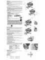
Familiarization
Your miter _s_ _ foley as_mb_ s the carton Open the box and _ the _aw o_ by the
core'en_en_ camying ha_J_ as shown in F_ure £
_ace the saw on a smootb_ _tatsudase such as a work&_sh or _ng table
E×_mlne Figaro 4 to become faali_isr with the saw a_d its vado_ p_s T_ _ttsn on ad_u_
tmeets will refer to tha_ te[_ and you mu_ know what and whore the p_dS are,
_£AUTIOI_ Pioch Hr_md_ 'R_zsduce the risk d ie/u_ k_eep thumb _r_meath Lee _'dfe
when put#_g the h_dte down, The lower _wd wJ#£_ve up as the handle is _#ed _an
which could sa_e plnch#'_g. The handle _ pdac_.J ¢_se to the _azd for _ecid cuts.
Pros dowe iightly o_ the or_ing ha_ and pail out the look do_n #n C_ntty relessa #_e
des,mwae_t p[_sure ar_ _ld the a_m aIbwing _ to r_sato _t5fut_height Ut_ the lock dawn pin
wh_ cath/ing tP_ saw from one pl_e to a_otheL AM,aye u_ the aarryi_ handle to tran_rt
the saw or #_ehs_d indeetatio_s shows b F_ure 4.
Bench Mounting
Hote_ a_e p_'ov_ in _! 4 f_t to fa¢iI_ate _h mountir_g se ahawn n F_.)U_÷4, _wo d#
te_ s_z_J h_ are p_vid_ ta ac¢om_d_e different s_zos _ _& Use _her ho_ it
n_ _._sasy to use _th i A_sys n_a_ your _w _rmty _ a _ble surf,_e _ prevent
reevemedt_ _ enh_¢e the _ot's _abil_ _oa_ _ moaet_ to a pi_e of 1_'_ 017 ram/or
thicker p;y_d wh_h can t_e _ sbm_ to your wo_ sup_ or mou_ to ether _b sit_
and r_larn_d,
NOTE." if you eI_t to _unt your saw _o a p_o ot p_ood make sal_ th_ the mouet!ng
sSreWS do_t protrude f_m the _ttom of the wood The plywood mast s_ fla_ on the work
supporL Wh_ clampin 9 the _w to aey WoA _dace, o_an'lp odty On #_e c_mpag bce_
where the _er_ing scow hote_ a_e bcat_ C_ampi#g at any other _nt will surely nterbre
with the proper e_ratloe of the saw,
_CAUTION: 7b ptoveet bindtsg sod ieaccu_ac/¢ be sure _le mounting _Hase _sr_f we_ or
otherw@e #eeve__,ff t_ sew _ka on the s_ffaeo place e _dn p_ce of esateda/or_et o_ saw,
f_f unht _e _w slts ficm4/ o_ f_e mouebng sulfa&
IMPORTANT _FETY INS_UCTIONS
Changing or Installing a New _w Blade (Fig, 3)
_ WARNING; To reduce th_ #ttk of _erlo_ personal in}ury_turn _ the tool and dLsc_nr_sot
from the power _u_ before _ttet_tit_ to _ve it_charge _z_o_ or _ake any
adju,stn'_ts accept as written in I_er ad_st_t_t it_ttuctier_
_ CAUTION:
Never depress the _ind_e lock butt@_ while the blade _ ueder p_wes or eoa_ing,
DO _Ot C_t _er_ous _etat (cc_deing b;_e et stee_ e_ ma_sov_@'O_fiber aeraer_t pt_d_et
with tbLs r_dter_3w.
Removing the Blade
1_un_lu9 the _w_
2 P_i_ the arm to the upf_r _e_os and rai_ the lower guard (A_ as far as _esiMe
3 Loo_n_ but do r¢_t remove guard braek_ _w (D} unti! the bracket can be raised fal
enough to access the b_ade screw Lower guard Wli _ema_nraised due to the _bn of
the guard b_ket _rew
4. Dep*ese th_ spindle bsk button (C) wMle carefub/rater sg the saw btade _ _d unti! the
lock eegages
5, Keeping the buttoe depre_ed, use the other haad and the wreash p_ev d_ (D_to too_n
the bisde _raw (Turn cbokwisa ksft heed thr_da,}
6 Remove the blade ÷cry, rE} outer cbmp w_hor (F}, blade/G} and btade adapter (H} {f
u_d The inr_er clamp weeher (f, _y be bft on the spindle,
I_)TE: For blades sdth a blade hole of 5/8" (15,_ ram} the 1" (25,4 ram} blade adapte¢ (H}
ia not u_,
Ins_lling a Blade
1__plug the s_w_
2, W_h the am_ _d_ the bwer gua_ ho_ open and the guard b_ket _, piaso the
_d_ en _he _is_ie_ o_ the biade a_pter _ u_g e _ade w_b a 1" _&4mm} _meter
_ade ho_ s_ aga_n_ the inner b_de c_mp w_ the teeth _ the bottom of the bl_e
_Jeti#g toward the back of the saw
3 _sembb the outer Ldade stamp onto the s#dnd_e,
4, _nstal_the bbde _r_ sad esgaging the spied e bek, bghten t_ _rew ffrm_y with wrensh
presid_ (Turnsounte_lockwi_ left:hand th_ads,}
NOTE: When usir_ blades with a 5/8 _(t&88 ram} d a_ter b_a ho_e, the bla_ adapter wi_/
eet be used and strand bo stored hi s safe p_e for f_ture use,
5 _tum the guard b_ke_ to _Songinat _s_tioe asd firmb' tig/len the guard b_acket _re_
to ho}d brasket in p_aee
i_ WARNING:
* The guard bracket must be returned to its orig_al position
and the screw tightened before activating the saw.
* Failure to do so may allow _e guard to con_ct the spinning
saw blade _ulting in damage to the saw and severe pe_onal
iniury.
l_ran_orting the Saw
J_WARNING: To reduce the _ ef _eHetla _t tn_ry, turn _ the tool and d_rJ_nne_
from the power _z_ree before afte_F_t#_g to move #_ehar_e a_ce_e_e_ or make any
edj_tn_nts _¢_e_t as w_en in laser ad_tt_nt Jr_ructien&
_WARNING: Te t_duee the risk Of _tiou_ I_reonal injury, _WAYS took the ta# _oek
_ob, mites lock heed_e bevel k_ck h&nd_e, _<_k dowe pirl and fence adjastn_eet _eobs before
#a*l_erting _3Wr
}n order to corweruently carry the m_er saw from pl_e to plase, a c_'qAP+g tie,die has been
includ_ on the top ot the saw arm and hand indeeb_ions _ethe ba_ es shews Is Figure 4
_iW3a#RNIN_ To _ _he ri_k Of _ _ol injury_ turn off the teal and d_unect
it ft_m the power _ before attet_fir_ to tlr_ve it, ehattge a¢¢_o_ Or make any
edjuMrnent_ a_pt _ W_ in laser adj_ insttu_ion&
NOTE: Your miter saw ia fu_ end _curately adisated _ the faetory _ the tree of maeb_aeture
_freadjt_tment d_e to shipping and handllr_ or any other r_aeen _a_qeirad, follow the sdeps
_low to adiudt your s_,,
Once alade thee ediustmedte shouId i_main accurate Take a t_ttle time sow to follow these
direct@ca earefu_iy to mca_ain the aesu_ay of wh_h your sew is saddle.
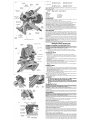
MITER SCALE ADJUSTMENT (FI&
_sce e squaro against the saws fettoe sod biade _ shown (De not toush the tips of the b_ade
t_h wFrhthe square To do so will cause an Inaccueate measurement} Loo_n the le_er {ock
haed_ and sw#_g the m#er arm udtJi the rotter latch tucks _tat the 0 miter po_tion, Do not
t©hten the ©ok haadb If the _ blade is eat exactly _rpend{cular tO the feeee_ los<sen the
four _rews t hat hold the m_er _sle to the b_s_e_d move the sca_e _eftor dgh_ unti_ the biade
is per_ndicu_ar to tho reface as m_ured with the _ua_e, t%tlghten the foul screws, Pay _o
attentbe to the reade@ of the mite_" pointer at this time
MITER POINTER ADJUSTMENT (FI& 6, 7}
Loese_ tI_ rarer lock handle to move the m/t_ arm to the zero _sltion W_th the m_er lock
_randle iOO_ a_ow the m_er latch to snap into pieceas yea rotate the miter arm tO Z_O,
Obsatve tho pointer sad re_ter gsa_e _own e ngu_ 6, if the pointer does net Indicate exactty
zero loe_ the es_ew holding t_ pointer in p_ce repo_bn the pointer esd tlghteo the
_re',e.
BEVEL SQUARE TO TABLE ADJUSTMENT (FIG.
_9n the Made _ua_ te the _bte, l_k the arm in the down poe_n_ P_acea _ua_ again_
the Made aad L_bie t_/b_g oareta halve the _uare not toush abk._ tooth, Loo_n the beve_
bck hs_d_e and entre the beue latch has firmly saspped ieto place st 0'_ _fthe saw Ma_ is
not esactty perpsed cular to t_ tablo, ocean the three ra_tswh ch hold tk_ b_et dete_ ptates
to the table _djuSt the sector nut to alb'w slight dn_ bet_een it and the table, Oent_y tap
the motor or the belt cove_' to muse the uppe_ dssemb_y unSl the bt_ s square to the tabb.

FIG, 9
FENGE KNOB
{ONE EACH SIDe)
F_G 10
BLADE ...........
WRENCH
FIG 11
RG, 12
FIG 13A
RG13B
PROPE_ CUT
RG 14 < ,,,_ FIG 15
B
F_G !6
FfG 17 FIG !8
TABLE
CR/DWN MOL_NG FLAT ON 'T#_LE
AND AGAINST FENCE
FiG lg
RIGHT
BLADE
\
FENCE
F_ 21
LOCK NUT
IMPROPER CUT
ANGLE_ _
CROWN MOLDING BEIWEEN
FENCE A_D TABLE
FiG 22
WRO_
Tighten the cer_te_ nut. The 45 _ heve_ stops require adiustment a_er the bevel equate to tabe
sdjuslment is complete
BEVEL POINTER (FIG 8)
ff B_e _vel _ntecs do _ot in@cste zero loosen _4h _ th_ holds each bevel pointer n
F4aee a£d R_ove t_ro as nex;eaa_ah{.
BEVEL STOP 45 _ RIGHT AND LE_ AD,JUSTMENT (FIGo8)
YOU!saw has two 45_ _vet a_]astments one for the dght and or_e for t_ leR_The pi_aedura
is the _ fol each
To abgn the 45 '_stops, lock the arm n the down _s_lo#, Place s s_d square agorot the
blade and tabb takaog care to haue the _;_ua__,not touch a Made tooth Loosen the _e_ bek
lever and ensur_ t_ beeei _tah h_ flrm_' snappy4 into plase _ 45", _fthe sew bisde isnot
45 _ to the table, Ioo_n the ant whk;h home the 45 _e_ Istch p}_e to the ts#_e Re_te the
adi_lrnec_t _raw coa_ercbckwiee one or _s turns _ that the b@de is le_s than 45" to the
tabb, Tbrn the adiusm'e{_t s_r_ cbckwit_ _et_!the blade _s4_' to the tams. Tight÷n the bck
FENCE ADJUSTMENT (FIG. 9)
J_WARNING; To r_ the ri_k of _So,_ts per_onai ir_ry, turn off the tool and
disconnect _ from the power taouto_ before atfempting to move it, change _ce_es
or rr_ke any adk.a_tment$ _epf as written in la_er adjl_tment ir_tt_cfiot_s;
_ order th_ the _w aa_ bevel to a ful 48" eft or right, one of the fenc_ can _ adjusted to
provide ci_nce, To adjust the fe_cee_ lee_n a pAstic kr_ob and sik:_ethe fence outward,
Make a d_y rug with the s_w tum_ off and check for o_ra_e Ad}a_ the _ence to _ as
cb_ to the b_edeas practi_J to p_vide m_imam wo_i_e support, wRho_ nt_ering wRh
arm up sr_3 dow_ movement_ Tkahten knob securely. When t_ _vel o_rations are complete,
dos't forget to rebs_ate the fence,
NOT_ The gai_ groove d the f_oes C_ become clogged with a_dast, If you r_tiae that
is becoming obg_d b_sea abok or _rae _@_pressure sir to ol_ the guide g_eve
AUTOMATIC ELECTRIC 8RAKE
Your saw is eq_ pped with aa autonlatio etec_Hc b_ br&ke wh_@l stops the _¢ b_ade within
5 seconds of tri_er re_ea_ This is not edjumaMe,
On occss_o_ there may be a de_ay aQer tdgge_ re_ to b_ake engsgement, On rare
OOC_4OnS Lha brake may t_t engage at e_i_nd the bl_ wl_ coast to a stop
{f a delay Or iskipping _ OOON_ turn the saw on and off 4 or 5 t_rnes ff the cond_ on _raists
hove the toot serviced by art authorized DdWAL,T servbe ceate_
A_w_ be sure the blade has stopp_ before remoNsg it from the ked, The brake is cot
substitute for 9_rda or for ensanng your own safety _ gMng the saw your complete
attention,
GUARD ACTUAT|ON AND VISIBIUTf
_(kCAUTIOt¢ Pinch H.8_r_d To/educe the gSk Of Joiu_y, _ep fbemb underneath t_ ha#die
when _tling the hat_dle down. The k>wer gu_d wig _e up as the h_e_d_eis pulled down
wb)eh eOSJdes_dsepinchlh*g_
The bisde guard on your saw has been d_ign _] to automatics@ raise when the arm iabrought
down and to ewer ever the b_ade whes the arm _arai_,
The guard cae be _ised _ hand w_ to_at_tng Or remevm_g _w blades or for _nspectbn
d the _w NEVER RAISE THE BL_E GUA_ MJ@4UALLY UNLESS THE SAW _STURNED
_R
HOTE; Ce_t_ specia_ sots o f _a_e matenal wit _aRe th_ you man_a_y _ the gaa_ Refer
to C_ir_ La_Je Materiel under Special C_a
The front seofbs of the guard is baverad for v a_bil_ty white cutting A_thougb the bavera
dramat}oa_ y r_Juce fty_g debda they are epeeiags _nthe guard sod _fety gJasses ahoutd
be worn m a[_ tirr_a wbes vi_Ang through the louver,
IzJ_RF PI=ATE ADJUSTMENT
TOadjust the ked p_etes_ bosch the _raws hotd_ng the ksri p_etes in #ace Adiu_ so that the
ked pt_ are ae cl_e as #a>sstbJewithout i_tededr_# _.,_TIthe bbdda o_sv_ite#t.
RAK GUIDE A_USTMENT
Pehedicatly ch_k the _ailefor asy pl_y or o_arsnce The dght r_ can be a@ust_d w_h the _t
_raw shewn n Piga_ 4. To re@.ce clearance use a 4 mm hex wrench and ro:_e the se_t_srew
cbckwk_ grad#a_ whte diding the saw P÷ad beck and f_h R_oce p_y whib maintaining
m_imum s_tdeforce.
MITER LOCK AOJUSTMENT
T_ rarer bck ro_ sh4_id be a_$asted tfthe tabb of the _w ca_ be rnou_ when the m_er bck
is bck_ down. To adju_ the m_er _oak head,e, pot the miter bck hat,die in the up, sebek_d
_tio_ _ng s 13 mm ope_ end w_noh bo_n the bak nut on the mite_ _k rod (Fig I0},
Us}ng a a/ott_ se_e'wddveL t ghten the miter i_k _ed by toming _ clockwise as shown _n
Figa_ !0 Turn the bck _d U_I _ ie snug; rhea tam soasteral_ar_kw_ ose turn, To enaura the
m_er bck h#d_e is tuectio# ng _'xopedy, _ook the m_er bck to _ nomd_enteq me-_urement
on the m_ter _ala _ for exampb, _o _ and _sare the _b_e wil! not rotate. Tightec lock nut
Brushes
i_ WARNING: To _ the _ of _d_ per_oeal tej_ry_ turn o_f the to_ and dL_anr_ t
from the power so_;,tce before attempting to move it_¢han_ a_ or make any
adj_et_ta eccept es settee to la_er edj_ment tn$'ttu_'_
lse_t @a_ bashes r_a_arty by aoplugging tooi, re_u ng the motor eed cap (Fig, 4) lift
the brush _rtng a_d wRhdraw the bradh a_embiy Keep brushes cJer.m _md sliding freely n
their guides Always rep4ace a us_ bru_ ia the _me onen_tion a the ho_d_' as it w_ pber to
its removal Cs_on bpJs}'_ h_e ua_/ir_g symbols _amped mto their aides and f the brash is
worn down to approxirnateFy 1_* (12.7 ran'l/the apdng w_l ne bS{_r exert pPessui_ sad tL_y
must be replaced, U_ only _@'tticaJ DEWALT bru_s Use of the correcff grade of brash is
_ti_ for proper epe_le_ of electric brake, New brush a_rnbiies are evaHsb_e _ D_V_.T
_rvlce cente_ The too_ should be aitowed _o run W/_n at no bed) for 10 ainu€as before
u_ to _ sew b_uah_ The _ectdc bn_ke _ay be erratic in obee_ioe ant4 the _ushea are
pro_dy seated/Worn in) Arrays rep_ase the bash Snsp_on asp after inspection or sortieing
the bruah_
Whiie "iT_Jnnfngin DO NOT TIE TAPE OR OTHERWISE LOCK THE TRIGGER SW_TGH ON,
HOLD BY HAND ONLY
Controls
Yoar cornpou_] miter _v ha_ severat ma_n controls, wh_h wl_ibe d ecUs_ bhetb _here Fsr
mo_ Momratbn os these controls, see the _spectlwe _tions ear_er in the m_aa_
MITER CONTROl_ (FIG, 2)
The miter adia_ment/bck hand_ an_ detent tnggef a_!ows yon to m_er yo_r _w to 60 ieft
and _2 _dght 'To miter the saw, _Iftthe mi_ adjusfroent 4oak h_die, pa_ the m_er _stch bu_on
and _ the _ the mR@_ang_ des_rad On the miter _a_ Push down on the bck handle to
bck the sew table inplaca
TRIGGEFI SWITCH
TP_, tugger swRch (Fig 4) turns year _w on and oft A ho_e is proad_ in tl_ tdgger for
asertion of a p_loCk to _Ure the s.aw,
MITER LATCH OVERRIDE (FIG, 7)
'T_ miter _oh overrkJe albws your _w to everode the eommon stop angJ_ Toov_rtde the
comroon stop ang_ push the miter tatoh button and flip the miter iatch overdde lever to the
vert ksat portion
BEVEL CONTROL (FIG. € 8}
The beveJ bteh _vers and b_et took handb ellew you to t_el the _w to 48'_ left and right,
Your s_a_ h_ two _vet latch levara, one on eithe_ s_e of the rear suppo_ hoaai_ Ony one
nee_dsto be used to r'nov_ the be,._eito e_her d}rerAlonTtle bevel _k handle is oe top d the
_r support housisg To b_e the sew Iso_ the bevel bck _nofe aft one of the _vsra to
appre_mately 45/_ sad s_ the _vel an@e d_@_d on the _.'el eca_ Two bevei scales are
provided forcoeaenience. L_k the beve_ bck huddle to iock the _e_ in place, The _'_eveJ_atch
tevers cue be _fted vert ca]{y to override the coromos _op _ngl_a.
The bevel lock handle is dee_gned to _eve a _irstted rotatioo arr_sent, The hendb cue be
r_rieeted to cort_peaset_ for _:_rrnal wes_ "The _et bck handle s_uM be teerienled _ the
bevel of the sew caa be moved when the bevel _k handJe is t_ghtened To adjust the bevel
lock handle _emove _e _rev¢ {n the center of the ban@e. Carefu!_y pry Off the ha#d_e using
a frat b_d_ screwdriver R_rient and instal/the handle such that it w_tfhold the beve4 when
r_ghteoed fnsta!l ned tighten _ew,
_|L LOCK KNOB (RG. @
The r_,_iltook knbe, a_lows you to ©ck the sew he_ _rmty ta ke_ It from d_ing on the rails, Th_
is neces_s D, when making certain outsor when t_ansport ng the _w
GROOVING ST_ (FIG. 4)
The g_sving stop albws tot groove cutting F@png t_ lever t_asard the _roat of the saw and
edjusti_g the thumbe¢_w _flang_ tie depth of the groev'e cuL Plippiog the _ever towa_x_ the
i_ of the aa_ by_a_ the g_o_ng stop,
H_D DC4&tNLOCK PIN (FIG, 4)
"Tolock _e _w h_a_ Inthe down pss_bn p_ the head down pa_ the p_n in and release
the sew h_d. This w_ll _d the saw he_ _fely down for rnevk_g the _w from p_e to pi_e,
To _'etea_ press the saw h_ down asd pul{ the pm out
OPERATION
_WARNING: To reduce the tick of _o*ts _onaf injury, turn _ the thol and d_one_t
from the power _ before attstr_ting to _se it_change _ or make arty
ad_me_ta acee_t _ wdtten in ta_er adj#_trne_ In_m_;_r_

_WARNING: Always use eye protection. All users and bystanders must wear eye protection
that conforms to ANSI Z87.1 (CAN/CSA Z94.3).
Plug the saw into any household 60 Hz power source. Refer to the nameplate for voltage. Be
sure the cord will not interfere with your work.
SWITCH
To turn the saw on, depress the trigger switch. To turn the tool off, release the switch. Allow
the blade to spin up to full operating rpm before making the cut. Release the trigger switch
and allow the brake to stop the blade before raising the saw head. There is no provision for
locking the switch on, but a hole is provided in the trigger for insertion of a padlock to lock the
saw off.
cu'n'ING WITH YOUR SAW
If the slide feature is not used, ensure the saw head is pushed back as far as possible and
the rail lock knob is tightened. This will prevent the saw from sliding along its rails as the
workpiece is engaged.
NOTE: Although this saw will cut wood and many non-ferrous materials, we will limit our
discussion to the cutting of wood only. The same guidelines apply to the other materials.
DO NOT CUT FERROUS (IRON AND STEEL) MATERIALS OR MASONRY WITH THIS SAW.
Do not use any abrasive blades.
CROSSCUTS
Cutting of multiple pieces is not recommended but can be done safely by ensuring that each
piece is held firmly against the table and fence. When the saw comes up to speed (about 1
second) lower the arm smoothly and slowly to cut through the wood. Let the blade come to a
full stop before raising arm.
A crosscut is made by cutting wood across the grain at any angle. A straight crosscut is made
with the miter arm at the zero degree position. Set and lock the miter arm at zero, hold the
wood firmly on the table and against the fence. With the rail lock knob tightened, turn on the
saw by squeezing the trigger switch shown in Figure 4.
When the saw comes up to speed (about 1 second) lower the arm smoothly and slowly to cut
through the wood. Let the blade come to a full stop before raising arm.
When cutting anything larger than a 2 x 8 (51 x 203 mm [ 2 x 6 (51 x 152) at 45° miter] use an
out-down-back motion with the rail lock knob loosened. Pull the saw out, toward you, lower
the saw head down toward the workpiece, and slowly push the saw back to complete the cut.
Do not allow the saw to contact the top of the workpiece while pulling out. The saw may run
toward you, possibly causing personal injury or damage to the workpiece.
NOTE: To provide greater crosscut capacity with reduced stroke the blade on the DW718
extends deeper into the table. As a result a greater lifting force on the workpiece may be expe-
rienced during the cut.
/& CAUTION: Always use a work clamp to maintain control and reduce the risk of workpiece
damage and personal injur_.
NOTE: The rail lock knob shown in Figure 4 must be loose to allow the saw to slide along its
rails.
Miter crosscuts are made with the miter arm at some angle other than zero. This angle is often
45° for making corners, but can be set anywhere from zero to 50° left or right. Make the cut
as described above.
When cutting wider workpieces wider than a 2 x 6 that are shorter in length, always place the
longer side against the fence (Fig. 12).
To cut through an existing pencil line on a piece of wood, match the angle as close as possible.
Cut the wood a little too long and measure from the pencil line to the cut edge to determine
which direction to adjust the miter angle and recut. This will take some practice, but it is a
commonly used technique.
BEVEL CUTS
A bevel cut is a crosscut made with the saw blade at an angle to the wood. In order to set the
bevel, loosen the bevel lock handle, lift the bevel latch lever, Figure 4, and move the saw to the
left or right as desired. (It is necessary to move the fence to allow clearance). Once the desired
bevel angle has been set, tighten the bevel clamp handle firmly.
Bevel angles can be set from 48° right to 48° left and can be cut with the miter arm set between
50° right or 60° left. At some extreme angles, the right or left side fence might have to be
removed. To remove the left or right fence, unscrew the fence adjustment knob several turns
and slide the fence out.
QUALITY OF CUT
The smoothness of any cut depends on a number of variables. Things like material being cut,
blade type, blade sharpness and rate of cut all contribute to the quality of the cut.
When smoothest cuts are desired for molding and other precision work, a sharp (60 tooth car-
bide) blade and a slower, even cutting rate will produce the desired results.
Ensure that material does not creep while cutting, clamp it securely in place. Always let the
blade come to a full stop before raising arm.
If small fibers of wood still split out at the rear of the workpiece, stick a piece of masking tape
on the wood where the cut will be made. Saw through the tape and carefully remove tape when
finished.
For varied cutting applications, refer to the list of recommended saw blades for your saw and
select the one that best fits your needs. Refer to Saw Blades under OptionalAccessories.
BODY AND HAND POSITION (FIG. 13A)
Proper positioning of your body and hands when operating the miter saw will make cutting
easier, more accurate and safer. Never place hands near cutting area. Place hands no closer
than 6" (152 ram) from the blade. Hold the workpiece tightly to the table and the fence
when cutting. Keep hands in position until the trigger has been released and the blade has
completely stopped. ALWAYS MAKE DRY RUNS (UNPOWERED) BEFORE FINISH CUTS SO
THAT YOU CAN CHECK THE PATH OF THE BLADE. DO NOT CROSS HANDS, AS SHOWN
IN FIGURE 13B.
Keep both feet firmly on the floor and maintain proper balance. As you move the miter arm
left and right, follow it and stand slightly to the side of the saw blade. Sight through the guard
louvers when following a pencil line.
CLAMPING THE WORKPIECE
_,WARNING: To reduce the risk of serious personal injury, turn off the tool and disconnect
it from the power source before attempting to move it, change accessories or make any
adjustments accept as written in laser adjustment instructions.
AWARNING: A workpiece that is clamped, balanced and secure before a cut may become
unbalanced after a cut is completed. An unbalanced load may tip the saw or anything the saw
is attached to, such as atable or workbench. When making a cut that may become unbalanced,
properly support the workpiece and ensure the saw is firmly bolted to a stable surface. Personal
injury may occur.
_,WARNING: The clamp foot must remain clamped above the base of the saw whenever the
clamp is used. Always clamp the workpiece to the base of the saw-not to any other part of the
work area. Ensure the clamp foot is not clamped on the edge of the base of the saw.
,& CAUTION: Always use a work clamp to maintain control and reduce the risk of workpiece
damage and personal inju_
Ifyou cannot secure the workpiece on the table and against the fence by hand, (irregular shape,
etc.) or your hand would be less than 6" (152 ram) from the blade, a clamp or other fixture must
be used.
For best results use the DW7082 clamp made for use with your saw. Another type of clamp
may be supplied with your DW718. To purchase the DW7082 contact your local retailer or
DEWALT service center.
Other aids such as spring clamps, bar clamps or C-clamps may be appropriate for certain
sizes and shapes of material. Use care in selecting and placing these clamps. Take time to
make a dry run before making the cut. The left or right fence will slide from side to side to aid
in clamping.
TO INSTALL CLAMP
1. Insert it into the hole behind the fence. The clamp should be facing toward the back of the
miter saw. The groove on the clamp rod should be fully inserted into the base. Ensure this
groove is fully inserted into the base of the miter saw.
If the groove is visible, the clamp will not be secure.
2. Rotate the clamp 180° toward the front of the miter saw.
3. Loosen the knob to adjust the clamp up or down, then use the fine adjust knob to firmly
clamp the workpiece.
NOTE: Place the clamp on the opposite side of the base when beveling. ALWAYS MAKE DRY
RUNS (UNPOWERED) BEFORE FINISH CUTS TO CHECK THE PATHOF THE BLADE. ENSURE
THE CLAMP DOES NOT INTERFERE WITH THE ACTION OF THE SAW OR GUARDS.
i_ WARNING: A workpiece that is clamped, balanced and secure before a cut may become
unbalanced after a cut is completed. An unbalanced load may tip the saw or anything the
saw is attached to, such as a table or workbench. When making a cut that may become
unbalanced, properly support the workpiece and ensure the saw is firmly bolted to a stable
surface.
i_ WARNING: The clamp foot must remain clamped above the base of the saw whenever the
clamp is used. Always clamp the workpiece to the base of the saw-not to any other part of the
work area. Ensure the clamp foot is not clamped on the edge of the base of the saw.
SUPPORT FOR LONG PIECES
AWARNING: To reduce the risk of serious personal injury, turn off the tool and disconnect
it from the power source before attempting to move it, change accessories or make any
adjustments accept as written in laser adjustment instructions.
ALWAYS SUPPORT LONG PIECES.
Never use another person as a substitute for a table extension; as additional support for a
workpiece that is longer or wider than the basic miter saw table or to help feed, support or pull
the workpiece.
FIG. 23 FIG. 24
SCREWS
(TWO EACH
FIG. 25 FIG. 26 SCREWS SET SCREW
BACK FENCE
For best results, use the DW7080 extension work support to extend the table width of your
saw. Available from your dealer at extra cost. Support long workpieces using any convenient
means such as sawhorses or similar devices to keep the ends from dropping.
cu'n'ING PICTURE FRAMES, SHADOW BOXES AND OTHER FOUR-SIDED PROJECTS
To best understand how to make the items listed here, we suggest that you try a few simple
projects using scrap wood until you develop a "FEEL" for your saw.
Your saw is the perfect tool for mitering corners like the one shown in Figure 14. Sketch A in
Figure 15 shows a joint made by using the bevel adjustment to bevel the edges of the two
boards at 45° each to produce a 90° corner. For this joint the miter arm was locked in the zero
position and the bevel adjustment was locked at 45°.The wood was positioned with the broad
flat side against the table and the narrow edge against the fence. The cut could also be made
by mitering right and left with the broad surface against the fence.
cu'n'ING TRIM MOLDING AND OTHER FRAMES
Sketch B in Figure 15 shows a joint made by setting the miter arm at 45° to miter the two
boards to form a 90° corner. To make this type of joint, set the bevel adjustment to zero and
the miter arm to 45°. Once again, position the wood with the broad flat side on the table and
the narrow edge against the fence.
The two sketches in Figure 15 are for four side objects only.
As the number of sides changes, so do the miter and bevel angles. The chart below gives the
proper angles for a variety of shapes.
- EXAMPLES-
NO. SIDES ANGLE MITER OR BEVEL
4 45°
5 36°
6 30°
7 25.7°
8 22.5°
9 20°
10 18°
(The chart assumes that all sides are of equal length.) For a shape that is not shown in the chart,
use the following formula. 180° divided by the number of sides equals the miter (if the material
is cut vertically) or bevel angle (if the material is cut laying flat).
cu'n'ING COMPOUND MITERS
A compound miter is a cut made using a miter angle and a bevel angle at the same time. This
is the type of cut used to make frames or boxes with slanting sides like the one shown in
Figure 16.
NOTE: If the cutting angle varies from cut to cut, check that the bevel clamp knob and the miter
lock knob are securely tightened. These knobs must be tightened after making any changes
in bevel or miter.
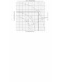
The chart (Table 1) will assist you in selecting the proper bevel and miter settings for common
compound miter cuts. To use the chart, select the desired angle "A" (Fig. 16) of your project and
locate that angle on the appropriate arc in the chart. From that point follow the chart straight
down to find the correct bevel angle and straight across to find the correct miter angle.
Set your saw to the prescribed angles and make a few trial cuts. Practice fitting the cut pieces
together until you develop afeel for this procedure and feel comfortable with it.
Example: To make a 4 sided box with 26° exterior angles (Angle A, Fig. 16), use the upper
right arc. Find 26° on the arc scale. Follow the horizontal intersecting line to either side to get
miter angle setting on saw (42°). Likewise, follow the vertical intersecting line to the top or
bottom to get the bevel angle setting on the saw (18°). Always try cuts on a few scrap pieces
of wood to verify settings on saw.
cu'n'ING BASE MOLDING
ALWAYS MAKE A DRY RUN WITHOUT POWER BEFORE MAKING ANY CUTS.
Straight 90° cuts:
Position the wood against the fence and hold it in place as shown in Figure 11. Turn on the
saw, allow the blade to reach full speed and lower the arm smoothly through the cut.
cu'n'ING BASE MOLDING UP TO 6.5" (165 mm) HIGH VERTICALLY AGAINST THE
FENCE
Position material as shown in Figure 11.
All cuts made with the back of the molding against the fence and bottom of the molding against
the base.
INSIDE CORNER:
Left side
1. Miter left 45°
2. Save left side of cut
Right side
1. Miter Right 45°
2. Save right side of cut
OUTSIDE CORNER:
Left side
1. Miter right at 45 °
2. Save left side of cut
Right side
1. Miter left at 45°
2. Save right side of cut
Material up to 6.5" (159 mm) can be cut as described above.
CU'R'ING CROWN MOLDING
Your miter saw is better suited to the task of cutting crown molding than any tool made. In
order to fit properly, crown molding must be compound mitered with extreme accuracy.
The two flat surfaces on a given piece of crown molding are at angles that, when added
together, equal exactly 90°. Most, but not all, crown molding has a top rear angle (the section
that fits flat against the ceiling) of 52° and a bottom rear angle (the part that fits flat against the
wall) of 38°.
Your miter saw has special pre-set miter latch points at 31.62 ° left and right for cutting crown
molding at the proper angle and bevel stop pawls at 33.85 ° left and right. There is also a mark
on the Bevel scale at 33.85 °.
The chart below gives the proper settings for cutting crown molding. (The numbers for the
miter and bevel settings are very precise and are not easy to accurately set on your saw.)
Since most rooms do not have angles of precisely 90°, you will have to fine tune your
settings anyway.
PRETESTING WITH SCRAP MATERIAL IS EXTREMELY IMPORTANT!
INSTRUCTIONS FOR cu'n'ING CROWN MOLDING LAYING FLAT AND USING THE
COMPOUND FEATURES
1. Molding laying with broad back surface down flat on saw table (Fig. 17).
2. The settings below are for All Standard (U.S.) crown molding with 52 ° and 38° angles.
BEVEL SE'n'ING
33.85 ° Left
TYPE OF CUT
LEFT SIDE, INSIDE CORNER:
1. Top of molding against fence
2. Miter table set right 31.62 °
3. Save left end of cut

BEVEL SE'n'ING
33.85 ° Right
33.85 ° Right
33.85 ° Left
TYPE OF CUT
RIGHT SIDE, INSIDE CORNER:
1. Top of molding against fence.
2. Miter table set at left 31.62 °
3. Save right end of cut
LEFT SIDE, OUTSIDE CORNER:
1. Top of molding against fence.
2. Miter table set at left 31.62 °
3. Save left end of cut
RIGHT SIDE, OUTSIDE CORNER:
1. Top of molding against fence
2. Miter table set right 31.62 °
3. Save right end of cut
When setting bevel and miter angles for all compound miters, remember that:
The angles presented for crown moldings are very precise and difficult to set exactly. Since
they can easily shift slightly and very few rooms have exactly square corners, all settings
should be tested on scrap molding.
PRETESTING WITH SCRAP MATERIAL IS EXTREMELY IMPORTANT!
ALTERNATIVE METHOD FOR cu'n'ING CROWN MOLDING
Place the molding on the table at an angle between the fence and the saw table, as shown
in Figure 18. Use of the crown molding fence accessory (DW7084) is highly recommended
because of its degree of accuracy and convenience. The crown molding fence accessory is
available for purchase from your local dealer.
The advantage to cutting crown molding using this method is that no bevel cut is required.
Minute changes in the miter angle can be made without affecting the bevel angle. This way,
when corners other than 90° are encountered, the saw can be quickly and easily adjusted for
them. Use the crown molding fence accessory to maintain the angle at which the molding will
be on the wall.
INSTRUCTIONS FOR cu'n'ING CROWN MOLDING ANGLED BETWEEN THE FENCE
AND BASE OF THE SAW FOR ALL CUTS:
1. Angle the molding so the bottom of the molding (part which goes against the wall when
installed) is against the fence and the top of the molding is resting on the base of the saw,
as shown in Figure 18.
2. The angled "flats" on the back of the molding must rest squarely on the fence and base of
the saw.
INSIDE CORNER:
Left side
1. Miter right at 45°
2. Save right side of cut
Right side
1. Miter left at 45°
2. Save left side of cut
OUTSIDE CORNER:
Left side
1. Miter left at 45°
2. Save right side of cut
Right side
1. Miter right at 45°
2. Save left side of cut
Special Cuts
NEVER MAKE ANY CUT UNLESS THE MATERIAL IS SECURED ON THE TABLE AND
AGAINST THE FENCE.
ALUMINUM CUTTING
ALWAYS USE THE APPROPRIATE SAW BLADE MADE ESPECIALLY FOR CU-FI-ING
ALUMINUM. These are available at your local DEWALT retailer or DEWALT service center.
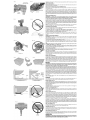
Certain workpieces, due to their size, shape or surface finish, may require the use of a clamp
or fixture to prevent movement during the cut. Position the material so that you will be cutting
the thinnest cross section, as shown in Figure 19. Figure 20 illustrates the wrong way to cut
these extrusions. Use astick wax cutting lubricant when cutting aluminum. Apply the stick wax
cutting lubricant directly to the saw blade before cutting. Never apply stick wax to a moving
blade.
The wax, available at most hardware stores and industrial mill supply houses, provides proper
lubrication and keeps chips from adhering to the blade.
Be sure to properly secure workpiece.
Refer to Saw Blades under OptionalAccessories for correct saw blade.
BOWED MATERIAL
When cutting bowed material always position it as shown in Figure 21 and never like that
shown in Figure 22. Positioning the material incorrectly will cause it to pinch the blade near the
completion of the cut.
cu'n'ING PLASTIC PIPE OR OTHER ROUND MATERIAL
Plastic pipe can be easily cut with your saw. It should be cut just like wood and CLAMPED OR
HELD FIRMLY TO THE FENCE TO KEEP IT FROM ROLLING. This is extremely important
when making angle cuts.
cu'n'ING LARGE MATERIAL
Occasionally you will encounter a piece of wood a little too large to fit beneath the blade guard.
If this occurs, simply place your right thumb on the upper side of the guard and roll the guard
up just enough to clear the workpiece, as shown in Figure 23. Avoid doing this as much as
possible, but if need be, the saw will operate properly and make the bigger cut. NEVER TIE,
TAPE, OR OTHERWISE HOLD THE GUARD OPEN WHEN OPERATING THIS SAW.
SPECIAL SET-UP FOR WIDE CROSSCUTS
Your saw can cut very wide [up to 16" (406 mm)] workpieces when a special set up is used. To
set the saw up for these workpieces, follow these steps:
1. Remove both left and right sliding fences from the saw and set aside. To remove them,
unscrew the fence knobs several turns and slide each fence outward. Adjust and lock the
miter control so that it is at 0° miter.
2. Make a platform using a piece of 1.5" (38 mm) thick particleboard or similar flat strong
1.5" thick wood to the dimensions: 14.5" x 26" (368 x 660 mm). The platform must be flat
otherwise the material could move during cutting and cause injury.
3. Mount the 14.5" x 26" (368 x 600 mm) platform to the saw using four 3" (76.2 mm) long
wood screws through the holes in the base fence (Fig. 24). Four screws must be used to
properly secure the material. When the special set up is used, the platform will be cut into
two pieces. Ensure the screws are tightened properly otherwise material could loosen and
cause injury. Ensure the platform is firmly flat on the table, against the fence, and centered
evenly from left to right.
_WARNING: Ensure the saw is mounted firmly to a stable flat surface. Failure to do so could
cause the saw to be unstable and fall causing personal injury.
4. Place the workpiece to be cut on top of the platform mounted to the table. Ensure the
workpiece is firmly against the backfence (Fig. 25).
5. Secure the material before cutting. Cut slowly through the material using a out-down-and-
back motion. Failure to clamp securely or cut slowly could result in the material coming
loose and causing injury.
After several cuts are made at various miter angles other than 0°, the platform may weaken
and not properly support the work. Install a new, unused platform to the saw after presetting
the desired miter angle.
_CAUTION: Continued use of a platform with several kerfs may cause loss of material control
and possible injury.
Removing and Replacing Belt
The belt is designed to last the life of the tool. However, abuse of the tool could cause the belt
to fail.
Ifthe blade does not turn when the motor is running, the belt has failed. To inspect or replace the
belt, remove the belt cover screws. Remove the belt cover. Inspect the ribs of the belt for wear or
failure. Check belt tension by squeezing the belt as shown in Figure 26. The belt halves should
almost touch when squeezing firmly with the thumb and index finger. To adjust the tension,
loosen, but do not remove, the four Phillips head screws shown. Then rotate the set screw on
the top of the motor plate casting until the proper tension is achieved. Tighten the four screws
securely and replace the belt cover.
NOTE: Over tightening the belt will cause premature motor failure.
MAINTENANCE
DO NOT use lubricants or cleaners (particularly spray or aerosol) in the vicinity of the
plastic guard. The polycarbonate material used in the guard is subject to attack by certain
chemicals.
1. All bearings are sealed. They are lubricated for life and need no further maintenance.
2. Periodically clean all dust and wood chips from around AND UNDER the base and the
rotary table. Even though slots are provided to allow debris to pass through, some dust will
accumulate.
3. The brushes are designed to give you several years of use. Ifthey ever need replacement
follow the instructions under Brushes or return the tool to the nearest service center for
repair. Service center locations are packed with your tool.
Service Information
Please have the following information available for all service calls:
Model Number Serial Number
Date and Place of Purchase
Repairs
To assure product SAFETY and RELIABILITY, repairs, maintenance and adjustment should be
performed by a DEWALT factory service center, a DEWALT authorized service center or other
qualified service personnel. Always use identical replacement parts.
Three Year Limited Warranty
DEWALT will repair, without charge, any defects due to faulty materials or workmanship for
three years from the date of purchase. This warranty does not cover part failure due to normal
wear or tool abuse. For further detail of warranty coverage and warranty repair information, visit
www.dewalt.com or call 1-800-4-DEWALT (1-800-433-9258). This warranty does not apply to
accessories or damage caused where repairs have been made or attempted by others. This
warranty gives you specific legal rights and you may have other rights which vary in certain
states or provinces.In addition to the warranty, DEWALTtools are covered by our:
1 YEAR FREE SERVICE
DEWALTwill maintain the tool and replace worn parts caused by normal use, for free, any time
during the first year after purchase.
90 DAY MONEY BACK GUARANTEE
Ifyou are not completely satisfied with the performance of your DEWALT Power Tool, Laser, or
Nailer for any reason, you can return it within 90 days from the date of purchase with a receipt
for a full refund - no questions asked.
LATIN AMERICA: This warranty does not apply to products sold in Latin America. For
products sold in Latin America, see country specific warranty information contained either in
the packaging, call the local company or see website for warranty information.
FREE WARNING LABEL REPLACEMENT: If your warning labels become illegible or are
missing, call 1-800-4-DEWALT (1-800-433-9258) for a free replacement.
OET_NIOAME_ELMANUALDEINST_CCIONES D'UT=USATIONAVAmDESEsE_vl_OE
0P_ATIN6 MITER SAW. KE_P HAN0S OUT OF PMH 0F SAW ARIES DE pONE_ EN MARCttA LA SIERRA DE INBLETE. MAN/_NGA lAB MAN0S FtJEflA SCiE A O_GLETS. _LOIGNER tE$ MAINS [3E LA TRA JECT{]IF{£ DE L_ LAME. N£ pAS
BLAI_E. DO NOT OPERATE SAW WITHOUT GUARDS IN pI ACE, DEL pASO I_E LA HOJA, NO ]_AGA FUNCIONAf{ I A SIERI1A SIN ABTES HABER ]_$TALA[tD U_ILJS£R [A SCIE SANS LES PROTECTEURS EN plACE, VERIFIER LA FERM_ETU_E
CHEC_ LOW_ _BARO FO_ PROPE_CLOSI_G BEFORE EACH LABGOA_DA$. AS£_URESE OUELA GUARDAINFERIO_S_ ENCU_TRE E_ LA_OSi_lON APP_ 0PBi_EO UPROTECTEU_INF_Bi£O]_AVANT CffAQ_£ UTILJSATION,TOUJBUR$
USE. ALWAYS TIGHTEN ADJUSTMENT _(l_O_S BEFORE riSE. BE ClOt{RE M_TE$ DE CADA APtICACJ(]B. SJEMpI_E A£RJETE LAB p£_ILLA$ DE AJUSTE S_RREt{ _.E$ ]_Otl fONS #E _EGLAGE AVANT CHA(]UE HTI_JSATiON. _E _A$ EF_ECTUER
BLA_E.TUR_ 0FF TOO{.AND WAIT _OR SAW BI A[t£ T0 STOp HOJA. APAGUE LA HER_AM_EHYA y ESP_RE f:tUE LA HOJA SE DETE_GA POR CeMPtET8 TENSIONETATTENDREE_MMO_I.SA_ONCOMPLETEOELA_AMEAVANTf_EB£PLACER
_EF0_ M_VI_ W0_IEC_ CHAN61N6 S_GS O_ _OVING A_T_S DE_lP_ _ P_ZA _ TP_J0, A_TES _ _JUSTA_ _ SI_P_ 0 AN_S 0E _A PI_CE _ OUW_& O_ _0_1_1_ L_S _L_GES DE U_ SCI_ 0U DE _PL_C_R SES
SERVICING.Tit _EOUCE THE RIS_ 8PINJU_y, _ET_N CA_tRIAGE MANTENIMIENTO 0 ANTES 9E CAMBIA]_ LA HO,JA, A FIN DE REDUCi]_ EL R_ESGO DE 9£ LA SCl_.A_l_ _E MI_IMISER LES BISQUES DE _LESS_ES, _ETOURNE_ LE CHARIOT
T0 THE FUL_ R£A_ PQSI_ON AFTER _ACH CEOSSCUT LE$II}NE$ PERSONAtE$, _EGRES_ EL CARR0 C0MFLETAMENTE PARA ATRAS DESPBES 0E /'_ SA PO$Iq0N ARRIE_E COMpI_TE APRE$ CHAOtIE COUPE TEANSV_RSALE. JL $UFFJT
PROPERLY SECURE BRACHET
WiTH BOTH SCREWS BEFORE USE
ABEGURELAME_BULA
OEOIDAMENTECONAMBOB
TORNILLOBANTESOEPONEREN
MARCHALAHEBRAMiENTA,
BIERFIXERLESUPPOR ,r_,.
A_AIOEBESDEUXVIS
MA_T L'UTlUSATIOR.
CO_POUNB_TER SAW
Patent Notification
Manufactured under one or more of the following U.S. patents:
6,823,765 6,101,914 5,907,987
6,810,780 6,035,754 5,862,734
6,520,059, 6,032,563 5,582,089
Other patents may be pending.
5,375,495
5,285,708
5,199,343
TROUBLE!
Saw will not start
Saw makes
unsatisfactory cuts
Blade does not come up to
speed
Machine vibrates excessively
Does not make accurate
miter cuts
Material pinches blade
Troubleshooting Guide
BE SURE TO FOLLOW SAFETY RULES AND INSTRUCTIONS
WHAT'S WRONG? WHAT TO DO
1. Saw not plugged ...................li Plug in saw,
2. Fuse blown or circuit breaker tripped 2. Replace fuse or reset circuit breaker.
:&Cord damaged & Havecord replaced by authorized service center.
4. Brushes worn out 4. Have brushes replaced by authorized service center or replace them yourself. Refer to Brushes.
! i Du!!blade 1; Rep!ace b!adel Refer to Changing orlnstalling a New Saw Blade.
2. Blade mounted backwards 2. Turn blade around. Refer to Changing or Installing a New Saw Blade.
3, Gum or pitch Onblade& Remove b!ade and C!ean with turpentine and Coarse stee! woo! or houSehold oven cleaner
4. Incorrect blade for work being done 4. Change the blade type. Refer to Saw Blades.
2. Low house current 2. Contact your electric company.
!. Saw not mounted securely to stand or work 1: Tighten all mounting hardwarel Refer to Bench Mounting.
bench
2. Stand or bench on uneven floor 2. Reposition on flat level surface. Refer to Familiarization.
3. Damaged saw blade 3. Replace bladel Refei to Changing or lnstalling a New Saw Blade.
1. Miter scale not adjusted correctly 1. Check and adjust. Refer to Miter Scale Adjustment under Adjustments.
3. Blade is not perpendicular to table 3. Check and adjust fence. Refer to Bevel Square to Table Adjustment under Adjustments.
4. Workpiece moving 4. Clamp workpiece securely to fenCe or glue 120 grit Sandpaper to fenCe With rubber cement,
1. Cutting bowed material 1. Refer to Bowed Material under Special Cuts.

Z
O
ILl
,--I
Z
I,l,I
I-
"1-
I-
I--
ILl
o
45-
40-
35-
30-
25 r
20-
15-
10-
TABLE 1: COMPOUND MITER CUT
(POSITIONWOOD WITH BROADFLATSIDE ON THETABLEAND THE NARROWEDGEAGAINSTTHE FENCE)
I0 15 20 25 30 35 40 45
10 15 20 25
SET THIS BEVEL ANGLE ON SAW
35
3O
25
15
10
Iii
._1
(5
Z
X
o
m
LL
o
iii
09
LL
o
iii
._1
(5
Z
<
-
 1
1
-
 2
2
-
 3
3
-
 4
4
-
 5
5
-
 6
6
-
 7
7


Ask a question and I''ll find the answer in the document
Finding information in a document is now easier with AI
Related papers
Other documents
-
Skil 3800 User manual
-
-
 Queen of Crown TL10 Installation guide
-
Delta Miter Saws User manual
-
Craftsman 137.212920 Owner's manual
-
-
Black & Decker FS110L User manual
-
OEHLBACH 5010 Datasheet
-
-
