Page is loading ...

VEA EL ESPAÑOL EN LA CONTRAPORTADA.
POUR LE FRANÇAIS, VOIR LA COUVERTURE ARRIÈRE.
SAVE THIS MANUAL FOR FUTURE REFERENCE.
INSTRUCTIVO DE OPERACIÓN, CENTROS DE SERVICIO Y
PÓLIZA DE GARANTÍA. ADVERTENCIA: LÉASE ESTE
INSTRUCTIVO ANTES DE USAR EL PRODUCTO.
INSTRUCTION MANUAL
FF
FF
SS
SS
11
11
11
11
00
00
LL
LL
11
11
00
00
””
””
CC
CC
OO
OO
MM
MM
PP
PP
OO
OO
UU
UU
NN
NN
DD
DD
LL
LL
AA
AA
SS
SS
EE
EE
RR
RR
MM
MM
II
II
TT
TT
EE
EE
RR
RR
SS
SS
AA
AA
WW
WW
T
T
HANK
HANK
YOU
YOU
FOR
FOR
CHOOSING
CHOOSING
F
F
IREST
IREST
ORM
ORM
!
!
G
G
O
O
T
T
O
O
WWW
WWW
.F
.F
IREST
IREST
ORMT
ORMT
OOLS
OOLS
.
.
COM
COM
/P
/P
RODUCT
RODUCT
R
R
EGISTRA
EGISTRA
TION
TION
T
T
O
O
REGISTER
REGISTER
YOUR
YOUR
NEW
NEW
PRODUCT
PRODUCT
.
.
BEFORE RETURNING THIS PRODUCT FOR ANY REASON PLEASE CALL
1-800-544-6986
BEFORE YOU CALL, HAVE THE CATALOG No. AND DATE CODE AVAILABLE. IN MOST CASES, A
BLACK & DECKER REPRESENTATIVE CAN RESOLVE THE PROBLEM OVER THE PHONE. IF YOU HAVE A SUGGESTION OR COMMENT, GIVE US A
CALL. YOUR FEEDBACK IS VITAL TO BLACK & DECKER.
For your convenience and safety, the following warning labels are on your miter saw.
ON MOTOR HOUSING:
WARNING: FOR YOUR OWN SAFETY, READ INSTRUCTION MANUAL BEFORE OPERATING SAW. WHEN SERVICING, USE
ONLY IDENTICAL REPLACEMENT PARTS. ALWAYS WEAR EYE PROTECTION.
ON FENCE: CLAMP SMALL PIECES BEFORE CUTTING. SEE MANUAL
ON GUARD: DANGER – KEEP AWAY FROM BLADE.
ON GUARD RETAINER PLATE: To reduce the risk of injury, read instruction manual before operating miter saw. When servicing,
use only identical replacement parts. Do not expose to rain or use in damp locations. Always use proper eye and respiratory
protection. Use only 10" (254mm) saw blades recommended for 5200RPM or higher with 5/8" arbor." Keep hands out of path of saw
blade. Do not operate saw without guards in place. Check lower guard for proper closing before each use. Always tighten adjustment
knobs before use. Do not perform any operation freehand. Never reach in back of saw blade. Never cross arms in front of blade.
Turn off tool and wait for saw blade to stop before moving workpiece, changing settings or moving hands. Disconnect power before
changing blade or servicing. To reduce the risk of injury, return carriage to the full rear position after each crosscut operation. Think!
you can prevent accidents.
2
Indicates an imminently hazardous situation which, if not avoided, will result in death or serious injury.
Indicates a potentially hazardous situation which, if not avoided, could result in death or serious injury.
Indicates a potentially hazardous situation which, if not avoided, may result in minor or moderate injury.
Used without the safety alert symbol indicates potentially hazardous situation which, if not avoided, may
result in property damage.
This manual contains information that is important for you to know and understand. This information relates to
protecting YOUR SAFETY and PREVENTING EQUIPMENT PROBLEMS. To help you recognize this information, we
use the symbols below. Please read the manual and pay attention to these sections.
SAFETY GUIDELINES - DEFINITIONS
GENERAL SAFETY RULES
READ AND UNDERSTAND ALL WARNINGS AND OPERATING INSTRUCTIONS BEFORE
USING THIS EQUIPMENT. Failure to follow all instructions listed below, may result in
electric shock, fire, and/or serious personal injury or property damage.
IMPORTANT SAFETY INSTRUCTIONS
Woodworking can be dangerous if safe and proper operating procedures are not followed. As with all machinery, there are certain
hazards involved with the operation of the product. Using the machine with respect and caution will considerably lessen the
possibility of personal injury. However, if normal safety precautions are overlooked or ignored, personal injury to the operator may
result. Safety equipment such as guards, push sticks, hold-downs, featherboards, goggles, dust masks and hearing protection
can reduce your potential for injury. But even the best guard won’t make up for poor judgment, carelessness or inattention.
Always use common sense
and exercise caution in the workshop. If a procedure feels dangerous, don’t try it. Figure out an
alternative procedure that feels safer. REMEMBER: Your personal safety is your responsibility.
CLAMP SMALL PIECES
BEFORE CUTTING. SEE MANUAL.
DANGER
KEEP AWAY
FROM BLADE
ON TABLE: (2 PLACES)
Some dust created by power sanding, sawing, grinding, drilling, and other construction activities contains
chemicals known to cause cancer, birth defects or other reproductive harm. Some examples of these
chemicals are:
• lead from lead-based paints,
• crystalline silica from bricks and cement and other masonry products, and
• arsenic and chromium from chemically-treated lumber (CCA).
Your risk from these exposures varies, depending on how often you do this type of work. To reduce your exposure to these
chemicals: work in a well ventilated area, and work with approved safety equipment, such as those dust masks that are specially
designed to filter out microscopic particles.
• Avoid prolonged contact with dust from power sanding, sawing, grinding, drilling, and other construction activities. Wear protective
clothing and wash exposed areas with soap and water. Allowing dust to get into your mouth, eyes, or lay on the skin may promote
absorption of harmful chemicals.
Use of this tool can generate and/or disperse dust, which may cause serious and permanent respiratory or
other injury. Always use NIOSH/OSHA approved respiratory protection appropriate for the dust exposure. Direct
particles away from face and body.
Wear appropriate hearing protection during use. Under some conditions and duration of use, noise from this
product may contribute to hearing loss.
DO NOT EXPOSE TO RAIN OR USE IN DAMP LOCATIONS.

3
1. FOR YOUR OWN SAFETY, READ AND
UNDERSTAND THE INSTRUCTION MANUAL
BEFORE OPERATING THE MACHINE. Learning the
machine’s application, limitations, and specific
hazards will greatly minimize the possibility of
accidents and injury.
2. USE CERTIFIED SAFETY EQUIPMENT. Eye
protection equipment should comply with ANSI
Z87.1 standards, hearing equipment should
comply with ANSI S3.19 standards, and dust
mask protection should comply with
NIOSH/OSHA certified respirator standards.
Splinters, air-borne debris, and dust can cause
irritation, injury, and/or illness.
3. DRESS PROPERLY. Do not wear tie, gloves, or
loose clothing. Remove watch, rings, and other
jewelry. Roll up your sleeves. Clothing or jewelry
caught in moving parts can cause injury.
4. DO NOT USE THE MACHINE IN A
DANGEROUS ENVIRONMENT. The use of
power tools in damp or wet locations or in rain
can cause shock or electrocution. Keep your
work area well-lit to prevent tripping or placing
arms, hands, and fingers in danger.
5. MAINTAIN ALL TOOLS AND MACHINES IN PEAK
CONDITION. Keep tools sharp and clean for best and
safest performance. Follow instructions for lubricating
and changing accessories. Poorly maintained tools and
machines can further damage the tool or machine
and/or cause injury.
6. CHECK FOR DAMAGED PARTS. Before using the
machine, check for any damaged parts. Check
for alignment of moving parts, binding of moving
parts, breakage of parts, and any other
conditions that may affect its operation. A guard
or any other part that is damaged should be
properly repaired or replaced. Damaged parts
can cause further damage to the machine and/or
injury.
7. KEEP THE WORK AREA CLEAN. Cluttered areas and
benches invite accidents.
8. KEEP CHILDREN AND VISITORS AWAY. Your shop is
a potentially dangerous environment. Children and
visitors can be injured.
9. REDUCE THE RISK OF UNINTENTIONAL
STARTING. Make sure that the switch is in the
“OFF” position before plugging in the power cord.
In the event of a power failure, move the switch
to the “OFF” position. An accidental start-up can
cause injury.
10. USE THE GUARDS. Check to see that all guards
are in place, secured, and working correctly to
prevent injury.
11. REMOVE ADJUSTING KEYS AND WRENCHES
BEFORE STARTING THE MACHINE. Tools,
scrap pieces, and other debris can be thrown at
high speed, causing injury.
12. USE THE RIGHT MACHINE. Don’t force a
machine or an attachment to do a job for which it
was not designed. Damage to the machine
and/or injury may result.
13. USE RECOMMENDED ACCESSORIES. The use
of accessories and attachments not
recommended by Black & Decker may cause
damage to the machine or injury to the user.
14. USE THE PROPER EXTENSION CORD. Make
sure your extension cord is in good condition.
When using an extension cord, be sure to use
one heavy enough to carry the current your
product will draw. An undersized cord will cause
a drop in line voltage, resulting in loss of power
and overheating. See the Extension Cord Chart
for the correct size depending on the cord length
and nameplate ampere rating. If in doubt, use the
next heavier gauge. The smaller the gauge
number, the heavier the cord.
15. SECURE THE WORKPIECE. Use clamps or a vise
to hold the workpiece when practical. Loss of
control of a workpiece can cause injury.
16. FEED THE WORKPIECE AGAINST THE DIRECTION
OF THE ROTATION OF THE BLADE, CUTTER, OR
ABRASIVE SURFACE. Feeding it from the other
direction will cause the workpiece to be thrown
out at a high speed.
17. DON’T FORCE THE WORKPIECE ON THE
MACHINE. Damage to the machine and/or injury
may result.
18. DON’T OVERREACH. Loss of balance can make
you fall into a working machine, causing injury.
19. NEVER STAND ON THE MACHINE. Injury could occur
if the tool tips, or if you accidentally contact the cutting
tool.
20. NEVER LEAVE THE MACHINE RUNNING
UNATTENDED. TURN THE POWER OFF. Don’t leave
the machine until it comes to a complete stop. A child or
visitor could be injured.
21. TURN THE MACHINE “OFF”, AND DISCONNECT
THE MACHINE FROM THE POWER SOURCE before
installing or removing accessories, before
adjusting or changing set-ups, or when making
repairs. An accidental start-up can cause injury.
22. MAKE YOUR WORKSHOP CHILDPROOF WITH
PADLOCKS, MASTER SWITCHES, OR BY
REMOVING STARTER KEYS. The accidental
start-up of a machine by a child or visitor could
cause injury.
23. STAY ALERT, WATCH WHAT YOU ARE DOING,
AND USE COMMON SENSE. DO NOT USE THE
MACHINE WHEN YOU ARE TIRED OR UNDER
THE INFLUENCE OF DRUGS, ALCOHOL, OR
MEDICATION. A moment of inattention while
operating power tools may result in injury.
24. THE DUST GENERATED by certain woods and
wood products can be injurious to your health.
Always operate machinery in well-ventilated areas,
and provide for proper dust removal. Use wood
dust collection systems whenever possible.
FAILURE TO FOLLOW THESE RULES MAY RESULT IN SERIOUS PERSONAL INJURY.

4
ADDITIONAL SAFETY RULES FOR MITER SAWS
Refer to them often and use them to instruct others.
FAILURE TO FOLLOW THESE RULES MAY RESULT IN SERIOUS INJURY.
SAVE THESE INSTRUCTIONS.
1. DO NOT OPERATE THIS MACHINE until it is
completely assembled and installed according to the
instructions. A machine incorrectly assembled can
cause serious injury.
2. OBTAIN ADVICE from your supervisor, instructor, or
another qualified person if you are not thoroughly
familiar with the operation of this machine. Knowledge
is safety.
3. FOLLOW ALL WIRING CODES and recommended
electrical connections to prevent shock or electrocution.
4. SECURE THE MACHINE TO A SUPPORTING SURFACE.
Vibration can possibly cause the machine to slide, walk,
or tip over, causing serious injury.
5. USE ONLY CROSSCUT SAW BLADES. Use only
zero-degree or negative hook angles when using
carbide-tipped blades. Do not use blades with deep
gullets. These can deflect and contact the guard, and
can cause damage to the machine and/or serious
injury.
6. USE ONLY BLADES OF THE CORRECT SIZE AND
TYPE specified for this tool to prevent damage to the
machine and/or serious injury.
7. USE A SHARP BLADE. Check the blade to see if it
runs true and is free from vibration. A dull blade or a
vibrating blade can cause damage to the machine
and/or serious injury.
8. INSPECT BLADE FOR CRACKS or other damage prior
to operation. A cracked or damaged blade can come
apart and pieces can be thrown at high speeds,
causing serious injury. Replace cracked or damaged
blades immediately.
9. CLEAN THE BLADE AND BLADE FLANGES prior to
operation. Cleaning the blade and flanges allows you to
check for any damage to the blade or flanges. A
cracked or damaged blade or flange can come apart
and pieces can be thrown at high speeds, causing
serious injury.
10. USE ONLY BLADE FLANGES specified for this tool to
prevent damage to the machine and/or serious injury.
11. CLEAR THE AREA OF FLAMMABLE LIQUIDS and/or
gas prior to operation. Sparks can occur that would
ignite the liquids and cause a fire or an explosion.
12. CLEAN THE MOTOR AIR SLOTS of chips and
sawdust. Clogged motor air slots can cause the
machine to overheat, damaging the machine and
possibly causing a short which could cause serious
injury.
13. TIGHTEN THE TABLE CLAMP HANDLE and any other
clamps prior to operation. Loose clamps can cause
parts or the workpiece to be thrown at high speeds.
14. NEVER START THE TOOL with the blade against the
workpiece. The workpiece can be thrown, causing
serious injury.
15. KEEP ARMS, HANDS, AND FINGERS away from the
blade to prevent severe cuts. Clamp all workpieces that
would cause your hand to be in the “Table Hazard
Zone” (within the red lines).
16. ALLOW THE MOTOR TO COME TO FULL SPEED
prior to starting cut. Starting the cut too soon can
cause damage to the machine or blade and/or serious
injury.
17. NEVER REACH AROUND or behind the saw blade. A
moving blade can cause serious injury.
18. NEVER CUT FERROUS METALS or masonry. Either of
these can cause the carbide tips to fly off the blade at
high speeds causing serious injury.
19. NEVER CUT SMALL PIECES. Cutting small pieces
(where your hand would be within 6” of the saw blade)
can cause your hand to move into the blade, resulting
in serious injury.
20. NEVER LOCK THE SWITCH in the “ON” position.
Setting up the next cut could cause your hand to move
into the blade, resulting in severe injury.
21. NEVER APPLY LUBRICANT to a running blade.
Applying lubricant could cause your hand to move into
the blade, resulting in serious injury.
22. DO NOT PERFORM FREE-HAND OPERATIONS
(wood that is not held firmly against the fence and
table). Hold the work firmly against the fence and table.
Free-hand operations on a miter saw could cause the
workpiece to be thrown at high speeds, causing
serious injury. Use clamps to hold the work when
possible.
23. PROPERLY SUPPORT LONG OR WIDE WORK-
PIECES. Loss of control of the workpiece can cause
serious injury.
24. AFTER COMPLETING CUT, release power switch and
wait for coasting blade to come to a complete stop
before returning saw to raised position. A moving blade
can cause serious injury.
25. TURN OFF THE MACHINE and allow the blade to
come to a complete stop prior to cleaning the blade
area or removing debris in the path of the blade. A
moving blade can cause serious injury.
26. TURN OFF MACHINE and allow the blade to come to
a complete stop before removing or securing
workpiece, changing workpiece angle, or changing the
angle of the blade. A moving blade can cause serious
injury.
27. PROPERLY SUPPORT LONG OR WIDE WORK-
PIECES. Loss of control of the workpiece can cause injury.
28. NEVER PERFORM LAYOUT, ASSEMBLY, OR SET-UP
WORK on the table/work area when the machine is
running. A sudden slip could cause a hand to move
into the blade. Severe injury can result.
29. TURN THE MACHINE “OFF”, disconnect the machine
from the power source, and clean the table/work area
before leaving the machine. LOCK THE SWITCH IN
THE “OFF” POSITION to prevent unauthorized use.
Someone else might accidentally start the machine and
cause injury to themselves.
30. BEFORE OPERATING THE SAW, check and securely
lock the bevel, miter, and sliding fence adjustments.
31. THE CUTTING HEAD MUST RETURN QUICKLY TO
THE FULL UP POSITION. Failure to do so will not allow
the lower guard to operate properly and may result in
personal injury. See manual section on “Adjusting the
Cuttinghead Return”.
32. THE CUTTING HEAD MUST RETURN QUICKLY TO
THE FULL UP POSITION. Failure to do so will not allow
the lower guard to operate properly and may result in
personal injury. See manual section on “Adjusting the
Cuttinghead Return”.
33. ADDITIONAL INFORMATION regarding the safe and
proper operation of power tools (i.e. a safety video) is
available from the Power Tool Institute, 1300 Sumner
Avenue, Cleveland, OH 44115-2851 (www.powertool
institute.com). Information is also available from the
National Safety Council, 1121 Spring Lake Drive,
Itasca, IL 60143-3201. Please refer to the American
National Standards Institute ANSI 01.1 Safety
Requirements for Woodworking Machines and the U.S.
Department of Labor regulations.
THIS MACHINE MUST BE GROUNDED WHILE IN USE TO PROTECT THE OPERATOR FROM ELECTRIC
SHOCK.
5
A separate electrical circuit should be used for your machines. This circuit should not be less than #12 wire and
should be protected with a 20 Amp time lag fuse. If an extension cord is used, use only 3-wire extension cords which
have 3-prong grounding type plugs and matching receptacle which will accept the machine’s plug. Before
connecting the machine to the power line, make sure the switch is in the “OFF” position and be sure that the electric
current is of the same characteristics as indicated on the machine. All line connections should make good contact.
Running on low voltage will damage the machine.
DO NOT EXPOSE THE MACHINE TO RAIN OR OPERATE THE MACHINE IN DAMP LOCATIONS.
1. All grounded, cord-connected machines:
In the event of a malfunction or breakdown, grounding
provides a path of least resistance for electric current to
reduce the risk of electric shock. This machine is
equipped with an electric cord having an equipment-
grounding conductor and a grounding plug. The plug
must be plugged into a matching outlet that is properly
installed and grounded in accordance with all local
codes and ordinances.
Do not modify the plug provided - if it will not fit the
outlet, have the proper outlet installed by a qualified
electrician.
Improper connection of the equipment-grounding
conductor can result in risk of electric shock. The
conductor with insulation having an outer surface that
is green with or without yellow stripes is the
MOTOR SPECIFICATIONS
GROUNDING INSTRUCTIONS
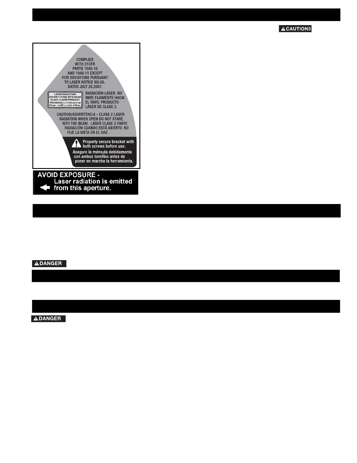
FOR LASER SAFETY OBSERVE THE FOLLOWING:
• LASER LIGHT - DO NOT STARE INTO BEAM, APERTURE, or into a reflection
from a mirror-like surface Fig. A & B.
• AVOID EXPOSURE - LASER LIGHT IS EMITTED FROM FRONT GUARD
APERTURE. Use of controls or adjustments, or performance of procedures
other than those specified herein may result in hazardous laser light exposure.
• DO NOT DISASSEMBLE LASER MODULE. The laser is a CLASS II LASER
PRODUCT that can emit laser power up to 1 mW MAX at 650 nm, which could
result in exposure with the module disassembled. The laser unit complies with
21 CFR 1040.10 and 1040.11.
• USE OF CONTROLS OR ADJUSTMENTS OR PERFORMANCE OF
PROCEDURES OTHER THAN THOSE SPECIFIED HEREIN MAY RESULT IN
HAZARDOUS RADIATION EXPOSURE.
• THE USE OF OPTICAL INSTRUMENTS with this product will increase eye
hazard.
• LASER RADIATION, avoid direct eye exposure, serious eye injury can result.
• DO NOT OPERATE IN EXPLOSIVE ATMOSPHERES, such as in the presence of
flammable liquids, gases, or dust.
• USE ONLY WITH THE SPECIFICALLY DESIGNATED BATTERIES. Use of any
other batteries may create a risk of fire.
• USE ONLY ACCESSORIES that are recommended by the manufacturer for your
model.
• ACCESSORIES THAT MAY BE SUITABLE FOR ONE LASER, may create a risk of
injury when used on another laser.
• REPAIRS AND SERVICING MUST be performed by a qualified repair facility.
Repairs performed by unqualified personnel could result in serious injury.
• DO NOT REMOVE OR DEFACE WARNING LABELS. Removing labels increases
the risk of exposure to radiation.
• THIS PRODUCT IS INTENDED for use in a temperature range of 41°F(5°C) -
104°F(40°C).
ADDITIONAL SAFETY RULES FOR THE LASER
Fig. B
Your machine is wired for 120 volt, 60 HZ alternating current. Before connecting the machine to the power source,
make sure the switch is in the “OFF” position.
Fig. A
equipment-grounding conductor. If repair or
replacement of the electric cord or plug is necessary,
do not connect the equipment-grounding conductor to
a live terminal.
Check with a qualified electrician or service personnel if
the grounding instructions are not completely
understood, or if in doubt as to whether the machine is
properly grounded.
Use only 3-wire extension cords that have 3-prong
grounding type plugs and matching 3-conductor
receptacles that accept the machine’s plug, as shown in
Fig. C. Repair or replace damaged or worn cord
immediately.
2. Grounded, cord-connected machines intended
for use on a supply circuit having a nominal rating
less than 150 volts:
POWER CONNECTIONS
For your convenience and safety the
following labels are on your tool.
available. The temporary adapter should be used only
until a properly grounded outlet can be installed by a
qualified electrician. The green-colored rigid ear, lug, and
the like, extending from the adapter must be connected
to a permanent ground such as a properly grounded
outlet box. Whenever the adapter is used, it must be
held in place with a metal screw.
6
EXTENSION CORDS
FOREWORD
Model FS110L is a 10" Compound Power Laser Miter Saw designed to cut wood, plastic, and aluminum. Compound
angle and bevel cutting are easy and accurate. It can crosscut up to 5-5/8" x 2-3/4", miter at 45° both left and right 4"
x 2-3/4", bevel at 45° left 5-5/8" x 1-5/8", and compound 45° x 45°, 4" x 1-5/8". It has positive miter at 0°, 15.5°,
22.5°,30° and 45° both left and right, and bevel stops at 0° and 45° degrees adjustable.
FUNCTIONAL DESCRIPTION
UNPACKING AND CLEANING
Carefully unpack the machine and all loose items from the shipping container(s). Remove the protective coating from
all unpainted surfaces. This coating may be removed with a soft cloth moistened with kerosene (do not use acetone,
gasoline or lacquer thinner for this purpose). After cleaning, cover the unpainted surfaces with a good quality household
floor paste wax.
NOTICE: The manual cover photo illustrates the current production model. All other illustrations are
representative only and may not depict the actual color, labeling, or accessories, and are intended to
illustrated technique only.
Use proper extension cords. Make sure
your extension cord is in good
condition and is a 3-wire extension cord which has a
3-prong grounding type plug and matching receptacle
which will accept the machine’s plug. When using an
extension cord, be sure to use one heavy enough to
carry the current of the machine. An undersized cord
will cause a drop in line voltage, resulting in loss of
power and overheating. Fig. E shows the correct gauge
to use depending on the cord length. If in doubt, use
the next heavier gauge. The smaller the gauge number,
the heavier the cord.
Fig. E
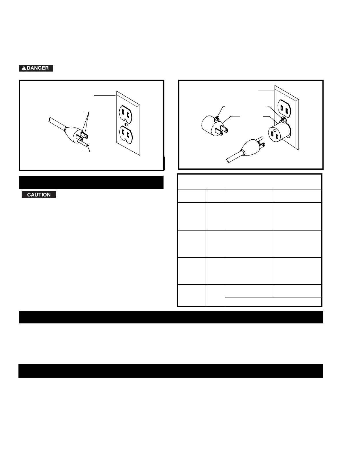
MINIMUM GAUGE EXTENSION CORD
RECOMMENDED SIZES FOR USE WITH STATIONARY ELECTRIC MACHINES
Ampere Total Length Gauge of
Rating Volts of Cord in Feet Extension Cord
0-6 120
up to
25 18 AWG
0-6 120 25-50 16 AWG
0-6 120 50-100 16 AWG
0-6 120 100-150 14 AWG
6-10 120
up to
25 18 AWG
6-10 120 25-50 16 AWG
6-10 120 50-100 14 AWG
6-10 120 100-150 12 AWG
10-12 120
up to
25 16 AWG
10-12 120 25-50 16 AWG
10-12 120 50-100 14 AWG
10-12 120 100-150 12 AWG
12-16 120
up to
25 14 AWG
12-16 120 25-50 12 AWG
12-16 120
GREATER THAN 50 FEET NOT RECOMMENDED
GROUNDED OUTLET BOX
CURRENT
CARRYING
PRONGS
GROUNDING BLADE
IS LONGEST OF THE 3 BLADES
GROUNDED OUTLET BOX
GROUNDING
MEANS
ADAPTER
IN ALL CASES, MAKE CERTAIN THAT THE RECEPTACLE IN QUESTION IS PROPERLY GROUNDED.
IF YOU ARE NOT SURE, HAVE A QUALIFIED ELECTRICIAN CHECK THE RECEPTACLE.
NOTE: In Canada, the use of a temporary adapter is not permitted by the Canadian Electric Code.
If the machine is intended for use on a circuit that has an
outlet that looks like the one illustrated in Fig. C, the
machine will have a grounding plug that looks like the
plug illustrated in Fig. C. A temporary adapter, which
looks like the adapter illustrated in Fig. D, may be used to
connect this plug to a matching 2-conductor receptacle
as shown in Fig. D if a properly grounded outlet is not
EXTENSION CORDS
Fig. C
Fig. D
7
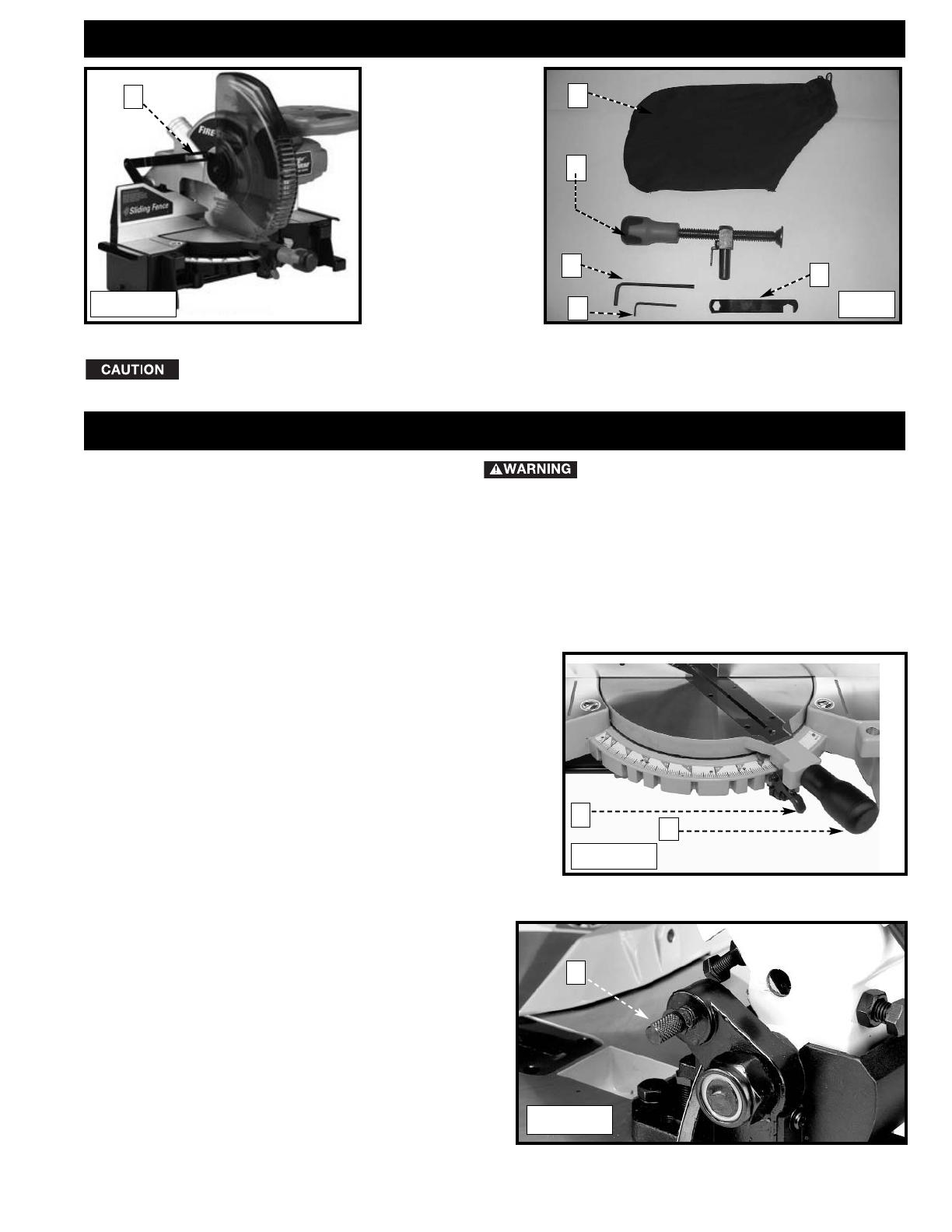
CARTON CONTENTS
1. Miter Saw
2. Dust Bag
3. Clamp
4. 5mm Hex Wrench
5. 1/8” Hex Wrench
6. 1/2” Blade Wrench
1
2
4
6
Lifting the miter saw by the switch handle can cause misalignment. Always lift the machine by
the base or the carrying handle.
ASSEMBLY
For your own safety, do not connect the
machine to the power source until the machine is
completely assembled, and you read and understand
the entire instruction manual.
Fig. 1 Fig. 2
3
Remove the miter saw and all loose items from the carton.
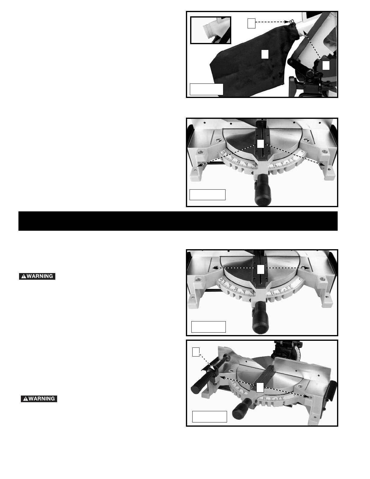
ROTATING TABLE
Loosen the table-lock handle one or two turns. Raise the index
lever (B) Fig. 3 and rotate the table to the desired position.
Tighten the table-lock handle (A) Fig. 3.
B
A
Fig. 3
MOVING CUTTINGHEAD TO THE UP POSITION
1. Push down on the cuttinghead and pull out the
cuttinghead lock knob (A) Fig. 4.
2. Move the cuttinghead to the up position.
A
Fig. 4
ASSEMBLY TOOLS REQUIRED
(Supplied)
* 5mm hex wrench
* 1/8” hex wrench
* 1/2” blade wrench
(Not supplied)
* Phillips head screwdriver
* A square to make adjustments
5
8
ATTACHING DUST BAG
Attach the dust bag (A) Fig. 5 to the dust spout (B)
making sure the wire ring (C) is engaged with the ridge
in the spout (see inset).
Fig. 5
A
C
B
FASTENING MACHINE TO SUPPORTING SURFACE
Before operating your compound miter saw, mount it to
a sturdy workbench or other supporting surface. Four
holes are provided, two of which are shown at (A) Fig. 6.
When frequently moving the saw from place to place,
mount the saw to a 3/4”piece of plywood. The tool
can then be easily moved from place to place and the
plywood can be clamped to a supporting surface using
“C” clamps.
A
Fig. 6
OPERATING CONTROLS AND ADJUSTMENTS
TABLE HAZARD AREA
The area inside the two red lines on
the table (A) Fig. 7 is designated as a
"HAZARD ZONE". Never place your
hands inside this area while the
machine is running. Maintain hands
6” from blade.
Keep your hands out of the path of
the saw blade. If necessary, clamp
the workpiece in place before making
the cut if hands would be within 6” of
blade.
A
Fig. 7
WORK CLAMP
Fig. 8
A
B
Position the work clamp in one of the two holes (B)
Fig 8 in the left or right side of the base. Use this
clamp, especially with short workpieces.
9
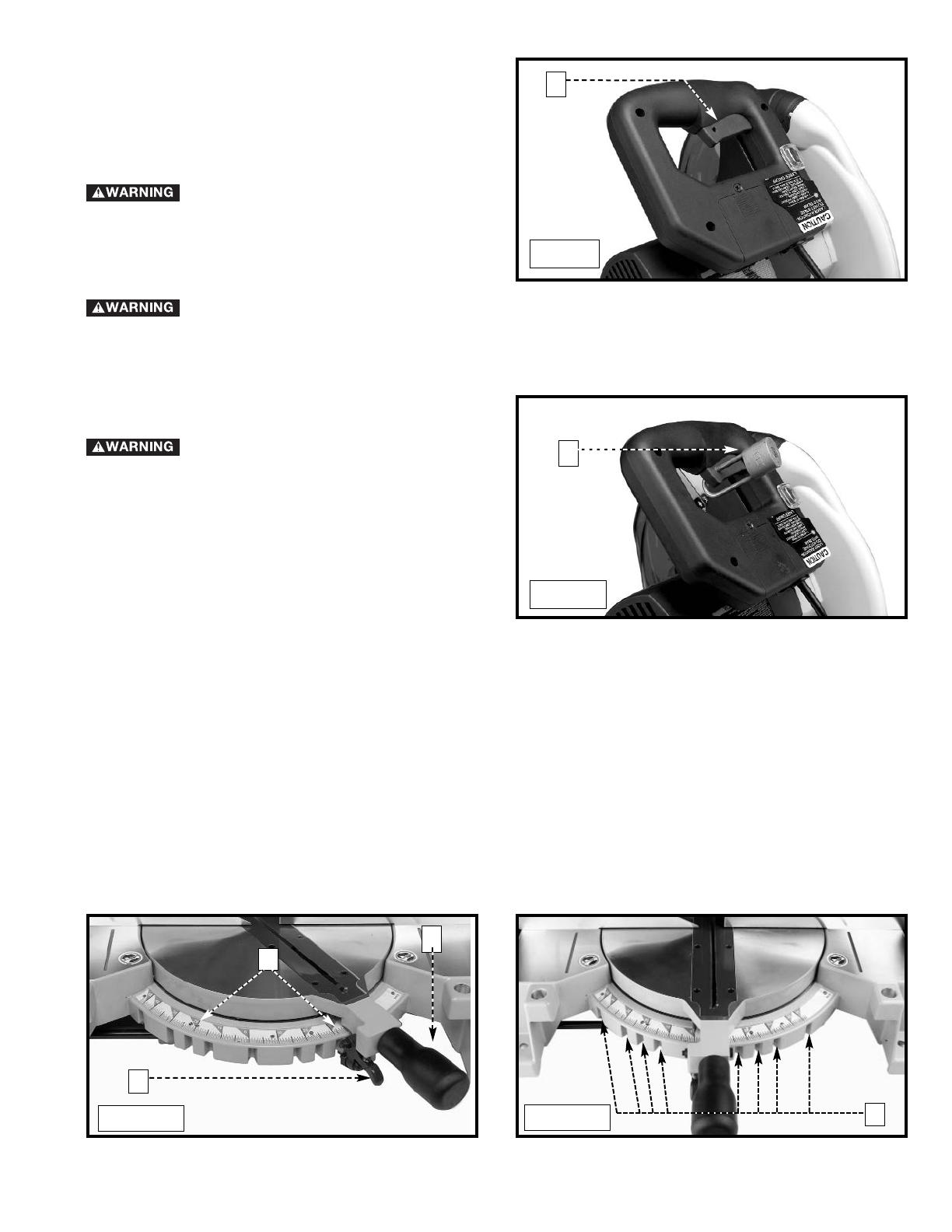
STARTING AND STOPPING THE MITER SAW
The torque developed during braking may loosen the arbor screw. Check the arbor screw
periodically and tighten, if necessary.
LOCKING THE SWITCH IN THE “OFF” POSITION
When the machine is not in use, the
switch should be locked in the “OFF”
position, using a padlock (B) Fig. 10
with a 3/16" diameter shackle to
prevent unauthorized use.
To start the miter saw, depress the switch trigger (A)
Fig. 9. To stop the miter saw, release the switch trigger.
This saw is equipped with an automatic electric blade
brake. As soon as the switch trigger (A) Fig. 9 is
released, the electric brake is activated and stops the
blade in seconds.
A
Fig. 9
B
Fig. 10
A turning saw blade can be
dangerous. After completing the cut,
release the switch trigger (A) Fig. 9 to
activate the blade brake. Keep the
cuttinghead down until the blade has
come to a complete stop.
ROTATING THE TABLE FOR MITER CUTTING
Your miter saw will cut any angle from a straight 90° cut to 47° right and left. Loosen the lock handle (A) Fig. 11 one
or two turns, depress the index lever (B), and move the control arm to the desired angle. TIGHTEN THE LOCK
HANDLE (A).
The miter saw is equipped with positive stops at the 0°, 15.0°, 22.5°,31.62° and 45° right and left positions. Loosen
the lock handle (A) Fig. 11, and move the control arm until the bottom of the index lever (B) engages into one of the
positive stops (C) Fig. 12. TIGHTEN THE LOCK HANDLE (A) Fig. 11. To disengage the positive stop, depress the
index lever (B).
In addition, an indicator (D) Fig. 11 is provided on the miter scale at the 33.9° right and left miter positions for cutting
crown molding. (Refer to the “CUTTING CROWN MOLDING” section of this manual).
IMPORTANT: Always tighten the lock handle (A) Fig. 11 before cutting.
B
A
C
Fig. 11
Fig. 12
D
10
POINTER AND SCALE
A pointer (A) Fig. 13 is supplied to indicate the actual angle of cut. Each line on the scale (B) represents 1 degree.
When the pointer is moved from one line to the next on the scale, the angle of cut is changed by 1 degree.
A
B
Fig. 13
When transporting the saw, lock the cuttinghead in the down position. Lower the cutting arm and push in the plunger (A)
Fig. 14 until the other end of the plunger (A) engages with the hole in the cutting arm (B).
IMPORTANT: Lifting the machine by the switch handle will cause misalignment. Always lift the machine by the
base or by the carrying handle (See Fig. 18).
LOCKING CUTTINGHEAD IN THE DOWN POSITION
A
B
Fig. 14
The cuttinghead of your compound miter saw can be
tilted to cut any bevel angle from a 90° straight cut off
to a 45° left bevel angle. Loosen bevel lock handle (A)
Fig. 15, tilt the cutting arm to the desired angle, and
tighten the lock handle (A).
Positive stops are provided to rapidly position the saw
blade at 90° and 45° to the table. Refer to the section
of this manual titled “ADJUSTING 90° AND 45°
DEGREE BEVEL STOPS.” The bevel angle of the
cutting arm is determined by the position of the pointer
(B) Fig. 15 on the scale (C).
In addition, a triangle indicator is provided on the bevel
scale at 33.9° for cutting crown molding. Refer to the
“CUTTING CROWN MOLDING” section of this
manual.
TILTING CUTTINGHEAD FOR BEVEL CUTTING
A
B
C
Fig. 15
ADJUSTING THE SLIDING FIT BETWEEN THE MOVABLE TABLE AND THE BASE
DISCONNECT THE MACHINE FROM THE
POWER SOURCE .
To adjust the sliding fit between the movable table and the base,
turn the nut (A) Fig. 12A clockwise to increase the
sliding fit (opposite to decrease the fit). This adjustment should not
be so tight that it restricts the rotating movement of the table, or
so loose that it affects the accuracy of the saw.
A
Fig. 12A
IMPORTANT: Move the sliding fence to provide clearance for the blade and guard. The degree of tilt determines how
far to move the sliding fence. Refer to the section “Adjusting Sliding Fence”.
11
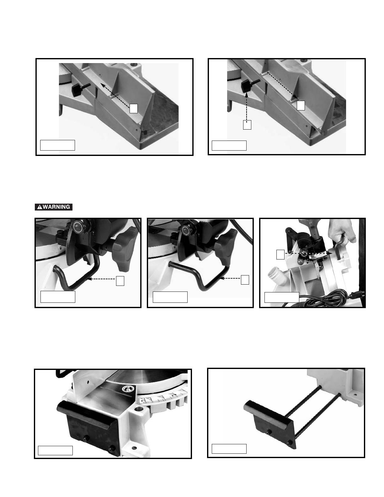
A rear support bar (A) Fig. 16 is provided to prevent the machine from tipping to the rear when the cuttinghead is
returned to the “up” position. For maximum support, the bar (A) Fig. 17 should be pulled out as far as possible. The
stabilizer bar (A) Fig. 18 can also be used to carry the machine.
REAR STABILIZER/CARRYING HANDLE
Fig. 16
Fig. 17
Fig. 18
A
A
A
SIDE SUPPORTS
This machine has two side supports to help stabilize the machine, and to help support long or wide workpieces.
The supports are located on either side of the table. The machine comes with the supports in the saw (Fig. 19A). To
utilize the supports, pull them out to their full length (Fig. 19B).
Fig. 19A
Fig. 19B
Fully extend the stabilizer bar before operating the saw.
The sliding fence (A) Fig. 15A provides support for extra large workpieces used with your saw. Set it as close as
possible to the saw blade. When miter cutting (blade 90° to the table and at an angle to the right or left), set the
fence all the way toward the blade (Fig. 15B). When bevel cutting, however (blade tilted at an angle to the table),
move the fence (A) far enough away from the blade to allow for proper clearance. To reposition the fence, loosen the
lock handle (B), and slide the fence (A) to the desired location. Tighten the lock handle (B).
ADJUSTING SLIDING FENCE
Fig. 15A
A
A
B
Fig. 15B

12
DISCONNECT MACHINE FROM POWER SOURCE.
1. Loosen the bevel lock handle and move the cutting arm all the way to the right. Tighten the bevel lock handle.
2. Place one end of a square (A) Fig. 22 on the table and the other end against the blade. Check to see if the blade
is 90° to the table (Fig. 22).
3. If an adjustment is necessary, loosen the locknut (A) Fig. 23. Turn the screw (B) until the head of the screw
contacts the casting (C) when the blade is 90° to the table. Tighten the locknut (B).
4. Loosen the bevel lock handle and move the cutting arm all the way to the left bevel position. Tighten the bevel
lock handle.
5. Use a combination square (A) Fig. 24 to see if the blade is at 45° to the table.
6. If an adjustment is necessary, loosen the locknut (A) Fig. 25. Turn the screw (B) until the screw (B) contacts the
casting (C) when the blade is 45 degrees to the table. Tighten the locknut.
7. Check to see that the bevel pointer (A) Fig. 26 is pointing to the 45° mark on the bevel scale. To adjust the bevel
pointer (A), loosen the screw (B) and adjust the pointer (A). Tighten the screw (B) securely.
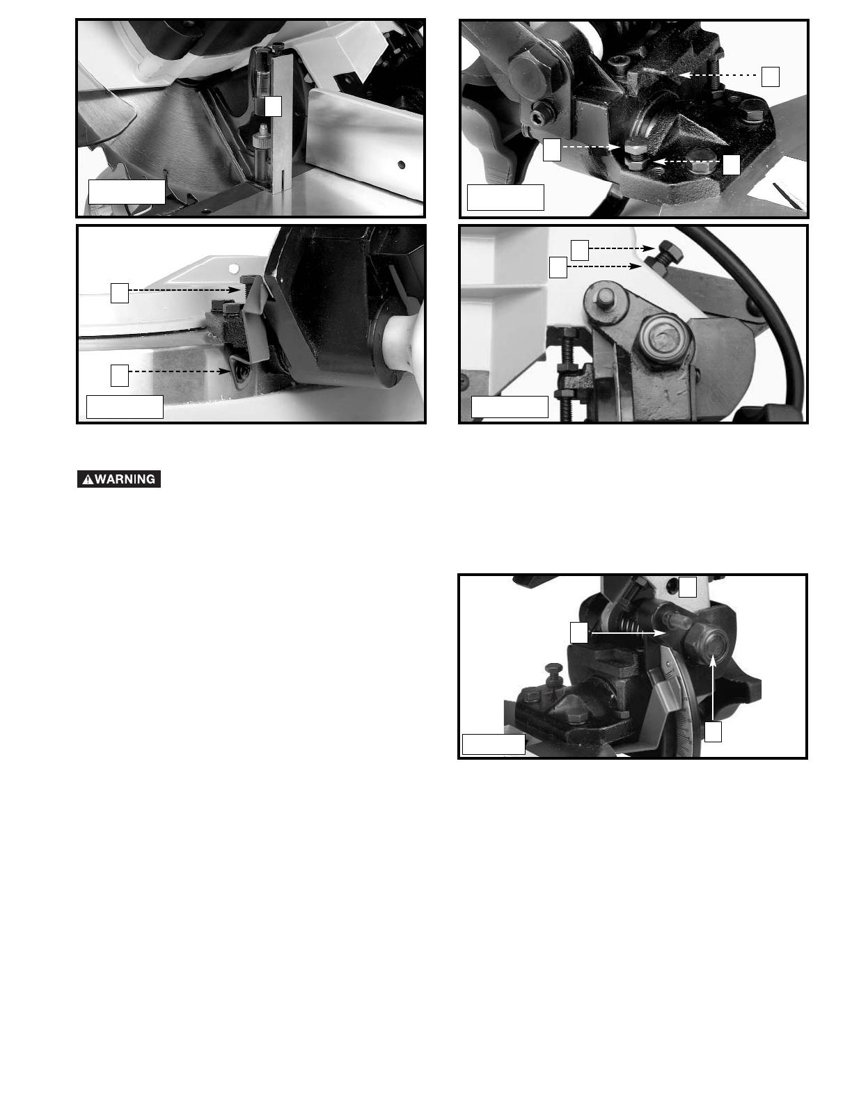
DISCONNECT MACHINE FROM POWER
SOURCE.
1. The downward travel of the saw blade should be
limited to prevent the saw blade from contacting
any metal surfaces of the machine. This adjustment
is made by loosening the locknut (A) Fig. 21, and
turning the adjusting screw (B) in or out.
2. Lower the blade as far as possible. Rotate the
blade by hand to ensure that the teeth do not
contact any metal surfaces. Adjust if necessary.
3. After the downward travel of the saw blade has
been adjusted, tighten the locknut (A).
ADJUSTING DOWNWARD TRAVEL OF SAW BLADE
Fig. 21
A
B
ADJUSTING 90° AND 45° BEVEL STOPS
A
Fig. 22
Fig. 23
C
B
A
DISCONNECT MACHINE FROM POWER
SOURCE.
1. Lower the cutting arm. The saw blade (A) Fig. 20
should be parallel to the left edge (B) of the table
opening.
2. If an adjustment is necessary, loosen two screws
(C) Inset, and move the cutting arm until the blade
is parallel with the left edge (B) of the table
opening and centered in the slot. Then tighten the
two screws (C).
A
B
C
Fig. 20
ADJUSTING BLADE PARALLEL TO TABLE SLOT
13
Fig. 24
Fig. 26
Fig. 25
A
A
B
C
A
B
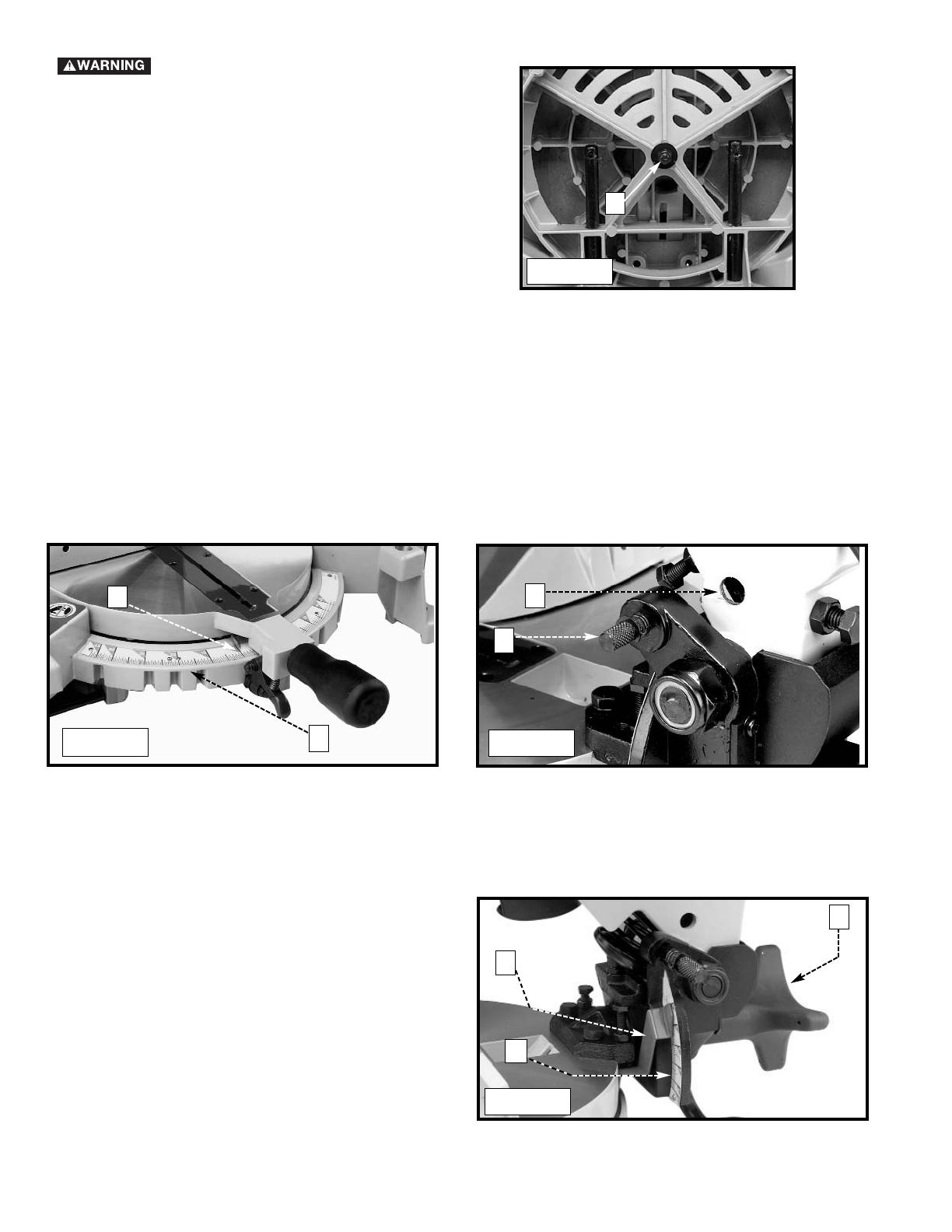
CUTTING HEAD MUST RETURN QUICKLY TO THE UP POSITION. DISCONNECT MACHINE
FROM POWER SOURCE.
The tension of the cuttinghead return spring was adjusted at the factory so that the cuttinghead returns to the “up”
position after a cut has been made. If it becomes necessary to adjust the spring tension:
Loosen the locknut (A) Fig. 27 and turn the screw (B) clockwise to increase, or counterclockwise to decrease the
spring tension. After adjustment, tighten the locknut (A).
ADJUSTING TENSION OF CUTTINGHEAD RETURN SPRING
A
B
Fig. 27
After a long period of time, an adjustment of the sliding fit
between the cuttinghead arm (B) Fig. 27A, and the
trunnion (C) may be necessary. To adjust, turn the nut (D).
This adjustment should not be so tight that it restricts the
sliding movement of the cuttinghead arm (B) or so loose
that it affects the accuracy of the saw cut.
ADJUSTING SLIDING FIT BETWEEN
CUTTINGHEAD ARM AND TRUNNION
C
D
Fig. 27A
B

14
Fig. 27B
ADJUSTING THE LOWER BLADE
GUARD
DISCONNECT THE MACHINE FROM
POWER SOURCE.
This machine incorporates a blade guard (A) Fig. 27B to
cover the rear section of the blade. After an extended
period of use, the movable lower blade guard may not
operate smoothly when the cuttinghead is lowered. This
can be corrected by adjusting nut (B) until the lower blade
guard moves freely.
Overtightening the nut could impair
guard movement.
NOTE: This unit has been designed with an articulating
rear guard. Before contacting the workpiece, the rear
guard will rotate upward to expose more of the blade as
the cuttinghead is lowered.
DO NOT REMOVE ANY OF THE BLADE
GUARDS.
Make sure that all guards are in place
and functioning properly before operating the saw.
Make sure that the fences are clear of
the guard and blade before operating the saw.
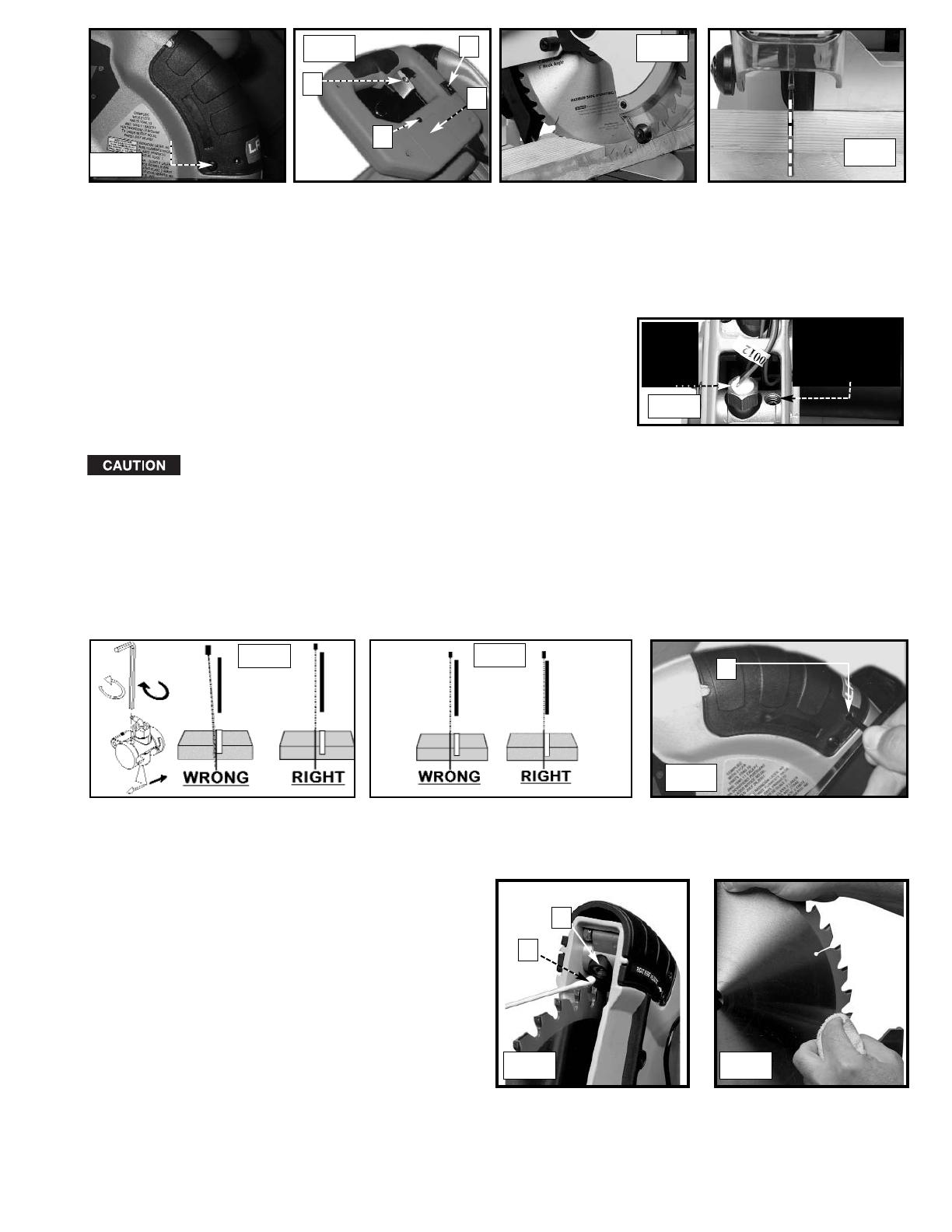
LASER USE AND ADJUSTMENT
The battery-operated laser unit (AA batteries not included) is mounted in a housing that is fitted into the upper blade
guard of the miter saw (Fig. A). (To insert the batteries, remove the screw (C) Fig. B, and slide the battery cover (D)
from the handle.) The laser projects a beam of light downward. This beam of light produces a red line-of-cut indicator,
where the saw blade will cut the workpiece. The laser unit is aligned at the factory and secured in place. A test cut
has been made with each saw to verify the laser setup. If your saw becomes misaligned or you desire additional
precision, use the following guidelines to fine tune your laser miter saw.
HOW THE LASER WORKS
HOW TO CHECK LASER ALIGNMENT
Make sure the saw is set to 0 degrees miter and bevel and clamp a 2"x 4" board on the saw. Create a partial/test cut
in the workpiece (Fig. C). Turn the laser “ON/OFF” switch (A) Fig. B) to the “ON” position. Leave the workpiece
clamped in place for the remainder of the adjustment.
Place and lock a padlock with a 3/16" shackle (B) Fig. B through the hole in the trigger switch to
prevent accidental motor startup.The padlock MUST remain in place during the adjustment procedure.
The laser line is properly positioned when the beam of light falls on the cut created by the blade (Fig. D).
A
B
15
3. Use the 1/8" hex wrench to turn the vertical alignment set screw (Fig. E).
If you move the cutterhead from the raised to the lowered position and
the laser line moves horizontally away from the blade, turn the vertical
alignment set screw clockwise to correct. If the laser line moves
horizontally toward the blade, turn the vertical alignment set screw
counter-clockwise to correct. (Fig. F)
4. Reinstall the cover removed in STEP 2.
Fig. F
Fig. G
TO SET KERF ADJUSTMENT
1. Use the 1/8" hex wrench (A) Fig. H to turn the kerf adjustment screw that sets the laser line to either side of the
test cut (Fig. G). To adjust the line, turn the kerf adjustment screw counter-clockwise to move the line toward the
blade and clockwise to move the line away from the blade.
2. Remove the padlock. The laser miter saw is ready for normal use.
Fig. H
BRASS
HEX
NUT
VERTICAL
ALIGNMENT
SET SCREW
Fig. E
Never turn the brass hex nut in Fig. E.
A
TO CHECK FOR VERTICAL ALIGNMENT
1. The vertical alignment is set correctly when the line does not move horizontally (sideways) as the cutting head is
raised and lowered. If the vertical alignment is correct, disregard this section and move to “TO SET KERF
ADJUSTMENT”.
2. If the vertical alignment is not correct, turn the kerf adjustment screw one half turn, clockwise. Remove the screws
on both sides of the laser unit cover (Fig. A). Remove the cover.
SCREW
Fig. A
Fig. C
Fig. D
Fig. B
A
B
C
D
LASER MAINTENANCE
For best laser performance, perform the following
maintenance regularly:
1. Carefully clean sawdust from each laser lens (A)
Fig. I with a cotton swab (B). Do not use solvents of
any kind since they may damage the lens. Avoid
touching sharp points of the saw blade with your
hands or fingers. Dust build-up can block the laser
and prevent it from accurately indicating the
line-of-cut.
2. Remove the blade from the saw and clean pitch
build-up from the blade (Fig. J) Pitch build-up can
block the laser and prevent it from accurately
indicating the line-of-cut.
Fig. I Fig. J
A
B

16
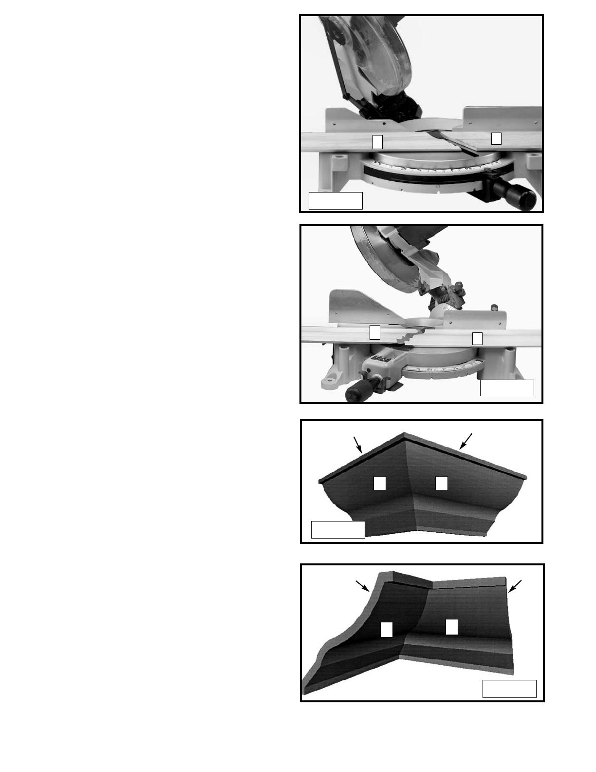
TYPICAL OPERATIONS AND HELPFUL HINTS
If the workpiece causes your hand to be in the hazard zone within 6” of the saw blade, clamp
the workpiece in place before making the cut.
Cuttinghead must return quickly to the full up position. Sluggish or incomplete return of the
cuttinghead will effect lower guard operation possibly resulting in personal injury.
1. Before cutting, make certain that the cutting arm and table are at the correct settings and firmly locked in place.
2. Place the workpiece on the table and hold or clamp it firmly against the fence (Fig. 28).
3. For best results, cut at a slow, even cutting rate.
4. Never attempt freehand cutting (wood that is not held firmly against the fence and table).
Fig. 28
A
AUXILIARY WOOD FENCE
Multiple or repetitive cut-off operations that result in small cut-off pieces (one inch or less) can cause the saw blade
to catch the cut-off pieces and project them out of the machine or into the blade guard and housing, possibly
causing damage or injury.
To limit the possibility of personal injury or blade guard damage, mount an auxiliary wood fence
on your saw. Keep the cutting head down until the blade stops whether or not you use an
auxiliary wood fence.
Holes are provided in the fence to attach an auxiliary fence (A) Fig. 29. This auxiliary fence is constructed of straight
wood approximately 1/2" thick by 3" high by 20" long.
NOTE: The auxiliary fence (A) is used ONLY with the saw blade in the 0° bevel position (90° to the table). When
bevel cutting (blade tilted), remove the auxiliary fence.
Fig. 29
A
A
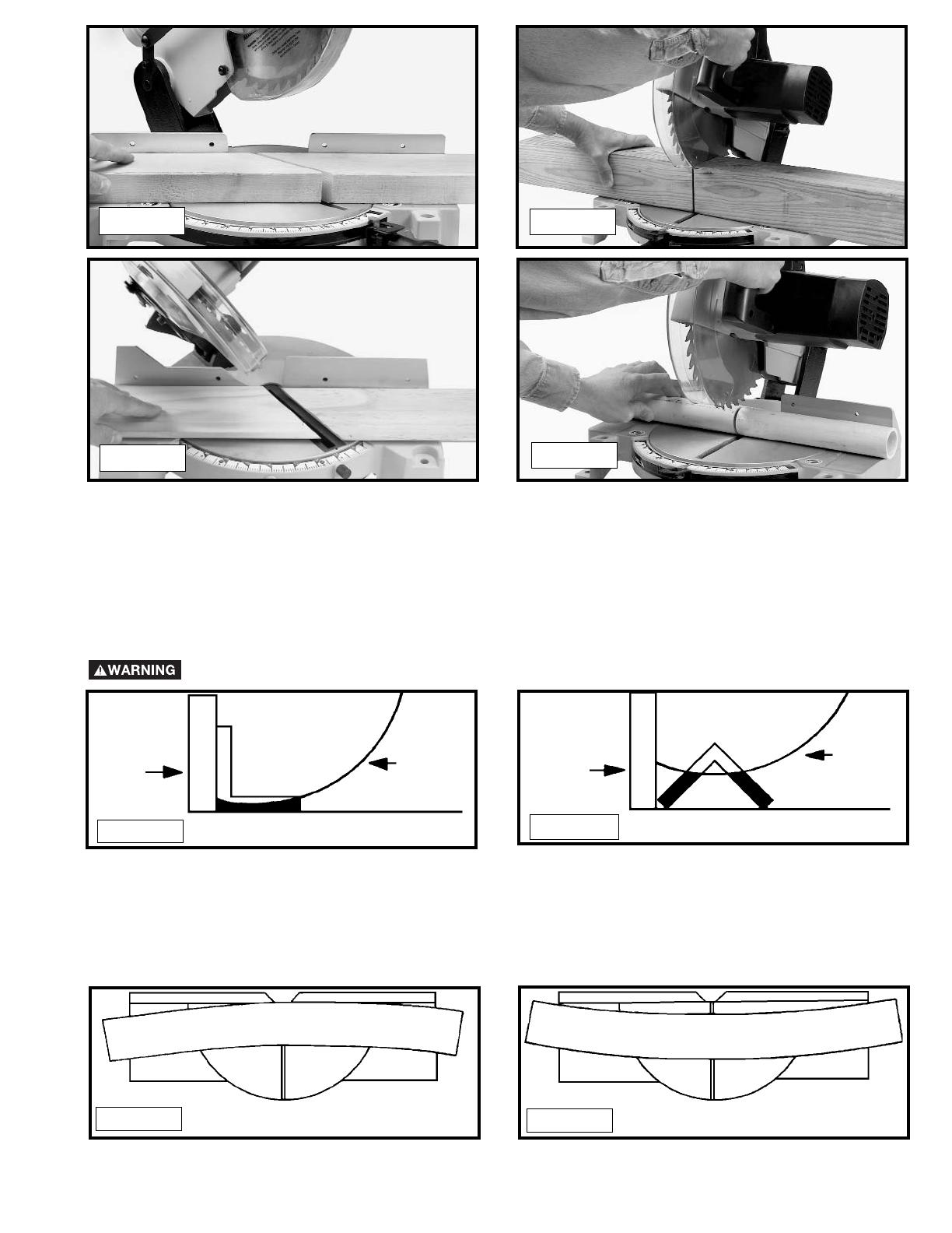
GENERAL CUTTING OPERATIONS
Fig. 30A Fig. 30B
1. Your machine has the capacity to cut standard 2 x 4’s lying flat or on edge, at the 45° right and left miter angles
(Fig. 30A).
2. A standard 2 x 6 can be cut in the 90° straight cut-off position in one pass (Fig. 30B) or at 45° right or left miter
angles (Fig. 30C).
3. Cutting a standard 4 x 4 can be accomplished with one pass (Fig. 30D).
4. This machine has the capacity to accurately cut crown moldings and other bevel-type cuts (Fig. 30E).
5. Cutting various sizes of plastic pipe is an easy job with this machine (Fig. 30F). Material must be CLAMPED OR
HELD FIRMLY TO THE FENCE TO KEEP IT FROM ROLLING.
This is extremely important when making angle cuts.
17
CUTTING ALUMINUM
Aluminum extrusions used for making aluminum screens and storm windows can easily be cut with your compound
miter saw when fitted with a blade recommended for this material. The blade supplied with this saw is not
recommended for cutting aluminum. When cutting aluminum extrusions, or other sections that can be cut with a saw
blade and are within the capacity of the machine, position the material so the blade is cutting through the smallest
cross-section (Fig. 31). The wrong way to cut aluminum angles is illustrated in Fig. 32. Be sure to apply a stick wax
to the blade before cutting aluminum stock. This stick wax is available at most industrial mill supply houses. The
wax provides proper lubrication and keeps chips from adhering to the blade.
Never apply lubricant to the blade while the machine is running.
FENCE
BLADE
RIGHT
FENCE
BLADE
WRONG
Fig. 32
Fig. 31
CUTTING BOWED MATERIAL
When cutting flat pieces, first check to see if the material is bowed. If it is, make sure the material is positioned on the
table as shown in Fig. 33.
If the material is positioned the wrong way (Fig. 34), the workpiece will pinch the blade near the completion of the
cut and may cause the saw to jump or move.
RIGHT
WRONG
Fig. 33
Fig. 34
Fig. 30E
Fig. 30F
Fig. 30C
Fig. 30D
18
B
Fig. 35
Fig. 36
A
D
C
B
D
A
C
CUTTING CROWN MOLDING
One of the many features of the saw is the ease of
cutting crown molding. The following is an example of
cutting both inside and outside corners on 52°/38° wall
angle crown molding.
1. Move the table to the 31.62° right miter position and
lock the table in position. NOTE: A positive stop is
provided to find this angle quickly.
2. Tilt the saw blade to the 33.86° left bevel position
and tighten bevel lock handle. NOTE: A triangle
indicator is provided on the bevel scale to find this
angle quickly.
3. Place the crown molding on the table with the
CEILING EDGE of the molding against the fence,
and make the cut, as shown in Fig. 35.
NOTE: The piece of crown molding used for the
outside corner will always be on the right hand side
of the blade, as shown at (A) Fig. 35. The piece of
crown molding used for the inside corner will always
be on the left hand side of the blade, as shown at
(B) Fig. 35.
4. To make the matching halves of the inside and
outside corners, rotate the table to the 31.62° left
miter position.
NOTE: A positive stop is provided to find this angle
quickly. The saw blade is already tilted to the 33.86°
bevel position from the previous cut.
5. Place the crown molding on the table with the
WALL EDGE of the crown molding against the
fence and make the cut. Again, the piece of crown
molding used for the outside corner will always be
on the right side of the blade, as shown at (C) Fig.
36. The piece of crown molding used for the inside
corner will always be on the left side of the blade, as
shown at (D) Fig. 36.
6. Fig. 36A illustrates the two outside corner pieces; (1)
being the piece cut at (A) Fig. 35 and (2) being the
piece cut at (C) Fig. 36.
7. Fig. 36B illustrates the two inside corner pieces; (1)
being the piece cut at (B) Fig. 35, and (2) being the
piece cut at (D) Fig. 36.
45-45 CROWN MOLDING
NOTE: If you are cutting crown molding that is
45°-45°, follow the same procedure above, with the
exception that the bevel position will always be at 30°
and the miter position will be 35-1/4° to the right or left.
1
2
2
1
Fig. 36A
Fig. 36B

19
MAINTENANCE
CHANGING THE BLADE
Use only cross-cutting saw blades.
When using carbide-tipped blades, do not use blades with deep gullets as they can deflect and
contact the guard.
Use only 10" diameter saw blades rated for 5200 rpm or higher, and have 5/8" diameter arbor holes.
Disconnect machine from power source.
REMOVE WRENCHES (A) FIG. 39 AND (A) FIG. 40 BEFORE STARTING THE MACHINE.
The cover must be returned to its original position and the screw tightened before activating the saw. •
Failure to do so may allow the cover to contact the spinning saw blade resulting in damage to the saw and
severe personal injury.
1. Remove the screw (A) Fig. 37 and rotate the cover (B) Fig. 38 to the rear.
2. To remove the saw blade, insert the 5mm hex wrench (A) Fig. 39 into the hex hole located on the rear end of the
motor shaft to keep the shaft from turning.
3. Use a wrench (A) Fig. 40 to loosen the arbor screw (C) by turning it clockwise.
4. Remove the arbor screw (C) Fig. 40, outside blade flange (B), and saw blade from the saw arbor.
5. Attach the new saw blade making certain that the teeth of the saw blade are pointing down at the front. Attach
the outside blade flange (B) Fig. 40, then the arbor screw (C), and turn it counterclockwise, using the wrench (A)
Fig. 40. At the same time, use the hex wrench (A) Fig. 39 to keep the arbor from turning.
6. Rotate the cover back to its original position and secure it in place with the screw removed in STEP 1.
Fig. 37
Fig. 38
Fig. 39
Fig. 40
A
B
A
C
B
A
NOTE: The no-load speed of this machine is 5200 rpm.

20
BRUSH INSPECTION AND
REPLACEMENT
Brush life varies. It depends on the load on the motor.
Check the brushes after the first 50 hours of use for a
new machine or after a new set of brushes has been
installed. After the first check, examine them after
about 10 hours of use until such time that replacement
is necessary. To inspect the brushes, proceed as
follows:
DISCONNECT MACHINE FROM POWER
SOURCE.
1. Remove three screws (A) Fig. 41 and remove motor
cover (B).
3. Fig. 43 illustrates one of the brushes (E) removed
from the holder (C). When the carbon on either brush
(E) is worn to 3/16”in length or if either spring (F) or
shunt wire is burned or damaged in any way, replace
both brushes. If the brushes are found to be
serviceable after removing, reinstall them in the same
position.
2. The brushes are located in the two holders (C)
Fig. 42. Remove spade type terminal connector (D) and
pull out brush holders (C).
A
B
Fig. 41
Fig. 42
D
C
C
Fig. 43
F
E
C
IMPORTANT
To assure product SAFETY and RELIABILITY, repairs, maintenance and adjustment (including brush inspection and
replacement) should be performed by authorized service centers or other qualified service organizations, always using
identical replacement parts.
/