Broan CMF2 Installation guide

Category
Fireplaces
Type
Installation guide
VentilAire™ III Whole-House Fresh Air Supply System
914098B – Sloped Roof Kit
Plastic
Clamps
(X2)
Metal
Clamps
(X2)
Plastic Inlet
Fitting w
Snap Fits
Sheet Metal Screw
For Optional Mounting
Location
Ceiling Ring
5” X 11’ Class I
Insulated Flexible Duct
INSTALLATION INSTRUCTIONS
IMPORTANT
ATTENTION INSTALLERS:
It is your responsibility to know this product better than your customer. This includes being able to
install the product according to strict safety guidelines and instructing the customer on how to operate
and maintain the equipment for the life of the product. Safety should always be the deciding factor when
installing this product and using common sense plays an important role as well. Pay attention to all safety
warnings and any other special notes highlighted in the manual. Improper installation of the unit or failure
to follow safety warnings could result in serious injury, death, or property damage.
These instructions are primarily intended to assist qualified individuals experienced in the proper
installation of this appliance. Some local codes require licensed installation/service personnel for this
type of equipment. Please read all instructions carefully before starting the installation. Return these
instructions to the customer’s package for future reference.
DO NOT DESTROY. PLEASE READ CAREFULLY & KEEP IN A SAFE PLACE FOR FUTURE REFERENCE.
2
MPORTANT SAFETY INFORMATION
INSTALLER: Please read all instructions thoroughly
before servicing this equipment. Pay attention to all safety
warnings and any other special notes highlighted in the
manual. Safety markings are used frequently throughout
this manual to designate a degree or level of seriousness
and should not be ignored.
WARNING - Indicates a
potentially hazardous situation that if not avoided, could
result in personal injury or death.
CAUTION - Indicates
a potentially hazardous situation that if not avoided, may
result in minor or moderate injury or property damage.
WARNING:
Unless noted otherwise in these instructions,
only factory authorized parts or accessory
kits may be used with this product. Improper
installation, service, adjustment, or maintenance
may cause explosion, fire, electrical shock or
other hazardous conditions which may result in
personal injury or property damage
WARNING:
The information listed below must be followed
during the installation, service, and operation
of this unit. Unqualified individuals should
not attempt to interpret these instructions or
install this equipment. Failure to follow safety
recommendations could result in possible
damage to the equipment, serious personal
injury or death.
Use caution when removing components or handling
this product. Personal injury can occur from sharp metal
edges present in all sheet metal constructed equipment.
ABOUT VENTILAIRE™
VentilAire™ is the most efficient way to introduce outdoorair
to interior environments. It works in conjunction with the
furnace blower and existing duct system and is able to
work independently when the heating and cooling system
is off. Best of all, VentilAire™ is a cost-effective way to
substantially improve air quality and help control attic
condensation in manufactured homes.
The VentilAire™ system is designed for use with Nortek
series gas, oil and electric furnaces and electric air
handlers.
How It Works
The home’s thermostat is the control device for selecting
continuous whole-house ventilation. When the thermostat
is in the whole-house ventilation position, the unit blower
will operate continuously; independent of COOL or HEAT
modes. When the furnace blower is operating, a negative
pressure (suction) is created in the furnace plenum. This
suction draws in fresh outdoor air which is mixed with the
homes return air then distributed through the home duct
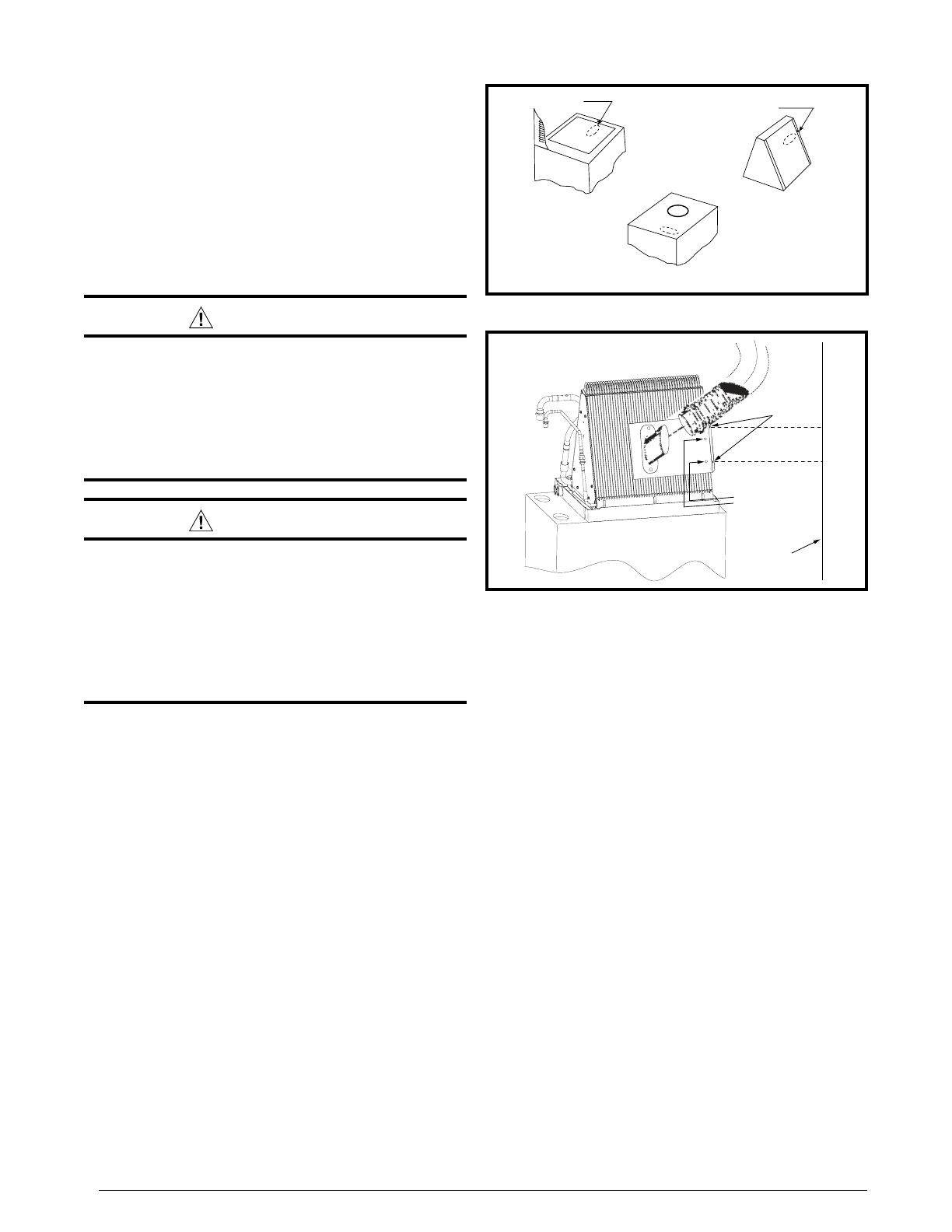
A/C Coil Mounting
Optional Attachment Kit
(wall or unit mounting)
Wall
Mounting
Holes
Wall
Mounting Holes
Figure 2. Downflow Electric Furnace with A/C
system. When HEAT or COOL modes are selected, the
fresh outdoor air and home return air are conditioned prior
to being distributed throughout the home.
VENTILAIRE™ INSTALLATION
DO NOT REMOVE THE OVAL KNOCKOUT (IN THE
FURNACE TOP) BEFORE COMPLETING STEP ONE.
1. Determine the location of the plastic inlet fitting:
Gas Furnace - Oval knockout located at the top, near
the front of the furnace. See Figure 1.
Air Handler - Oval knockout located on the sides of
the air handler.
Downflow Electric Furnace - The plastic inlet fitting
may be mounted in the rear of the cabinet over the
return air filter. When using an optional air conditioning
coil, it may be mounted to the front or rear coil end-plate
flange using the mounting holes provided. See Figure
1.
NOTE: An optional VentilAire™ attachment kit (P/N
919328) may be purchased to attach the plastic inlet
fitting to the coil or wall in Heat/Cool and Heat only
(no coil) applications. This bulk kit is supplied with 24
brackets and fasteners. The plastic inlet fitting snaps
into the bracket opening without screws. See Figure 2.
Electric Furnace with Nortek A/C coil - Align and
fasten the VentilAire™ attachment bracket with the
holes in the coil end-plate flange. See Figure 2.
Optional A/C Coil
Gas Furnace
Electric Furnace
Mounting
Hole
Mounting
Hole
Figure 1. Plastic Inlet Fitting Location
3
Electric Furnace with non-Nortek A/C coil – When
using other brands of coils, the installer has the option
to attach the bracket to the wall of the furnace cavity.
Fastening must penetrate into a framing member or
sheetrock anchors. See Figure 2.
Electric Furnace, Heating only, no coil - The bracket
may also be mounted directly to the front of the electric
furnace. See Figure 3 (page 3). In wall mounting
applications, the bracket should be positioned at the
rear of the unit with the entire bracket opening located
over the return air inlet.
NOTE: In all applications, the VentilAire™ system should
be positioned no more than 2 inches from the return air
inlet opening of the furnace or coil without interfering
with the filter or coil fins.
Upflow Electric Furnace - a special adaptor (914427)
may be applied over the square refrigerant line knockout.
2. For oval knockout installation, place the plastic inlet
fitting with locking tabs onto the sheet metal. The side
with tabs further apart (back) should be inserted first,
then push gently on the front in the center of the part
until front tabs fall below the sheet metal and release.
Part will tighten securely in place after application
of metal clamp. NOTE: For optional locations use
the sheet metal screw provided through one of the
clearance holes on the plastic inlet flange.
3. Cut approximately a 7-inch diameter hole in the ceiling
directly above the duct fitting. Avoid ceiling joists and
other obstructions in the ceiling cavity.
WALL
Wall
Mounting
or
Unit
Mounting
Figure 3. Downflow Electric Furnace
(with Heat Only)
Roof
Vent
3'
min.
Furnace
Flue
Roof
Cap
NOTE: 36in
2
recommended at
each end of home per ventilator
3'
min.
Figure 4. Roof Spacing
Table 1. VentilAire™ III & IV Application Chart
Furnace
Model
Fresh Air Supply CFM - Blower Speed
Low Med-Low Med-High High
M1*B 50 65 85
M1*C 60 70 80
90
M4RC 75
90
M4RL 80
90
M7(R,T)L / MG2S 65 80 90
E3EB 50 70 80
90
B(5,6)BV-000K-B 50 65
90
B(5,6)BV-000K-C 70
90
NOTE: Manufactured homes installed ventillation system capacity
should be in compliance with HUD 3280.103(6)(1-6)
ATTIC
CEILING
DUCT SYSTEM
FLOOR
REGISTER
ROOF
FLEXIBLE
DUCT
BLOWER
FURNACE
ROOF JACK
SOFFIT
VENT
FRESH
AIR
CEILING
RINGS
BACK OF
F
URNACE
Figure 5. General Install Setup
CAUTION:
The roof cap MUST be located at least 3 feet
from any plumbing vent or exhaust vent (gas
or oil furnaces, water heater, fireplace, etc.).
4. Determine location of roof opening. NOTE: The roof
cap assembly should be located as closely as possible
to the center of the home, allowing connection of the
fresh air intake to the furnace using the 11-foot length
of flexible duct provided. See Figure 4.
5. Cut approximately a 7 1/2-inch circular or square
opening in roof.
6. Route flexible duct through ceiling hole between the
roof opening and the furnace area. See Figure 5.
7. Attach one end of flexible duct to bottom flange of roof
cap assembly. Secure the inner duct with one of the
metal clamps provided and the insulation duct with
one of the plastic clamps provided.
8. Apply appropriate caulking or roof sealing material to
underside of roof cap flashing to form a continuous
strip around the underside of the perimeter of the
flashing.
9. Attach roof cap assembly to roof. Press down firmly
over caulking on flashing, to ensure a waterproof seal.
Secure roof cap flashing with appropriate fasteners for
your specific roof construction. As an added protection
INSTALLER: Do Not Discard These Instructions. After completing the installation, return these instructions to the
equipment owner for future reference. Complies with H.U.D. Manufactured Home Construction & Safety Standards.
708728C
(Replaces 708728B)
Kits conform to H.U.D. Manufactured Home Construction and Safety Standard for ventilation, paragraph 3280.103(b)(1-6). Effective May 30, 2006.
Specifications & illustrations subject to change without notice or incurring obligations (02/19).
O’Fallon, MO, © Nortek Global HVAC LLC 2019. All Rights Reserved.
against leaks, coat the roof cap flashing and fasteners
with roofing compound.
10. Pull slack in flexible duct down through ceiling hole to
inlet fitting, being careful not to damage or severely
bend the duct. Trim off any excess length of duct to
minimize restrictions.
11. Shape end of flexible duct to fit over collar on inlet
fitting and attach with clamps provided.
12. Install ceiling ring around flexible duct and attach
to the ceiling. NOTE: Alternate replacement ceiling
ring(s) or other suitable materials may be used in
place of supplied rings.
Moisture Control Recommendations
Follow the recommendations of the manufacturer of
your home to maintain low levels of moisture in your
home.
• When moisture-producing activities (cooking, bathing,
etc.) are occuring, operate exhaust fans.
Avoid hanging clothes to dry within your manufactured
home.
• Vent all fuel burning appliances.
• Avoid using humidifiers.
Avoid having large quantities of houseplants, pools of
water, and other moisture-producing conditions.
Place a vapor barrier (such as plastic sheeting) on top
of the ground underneath your manufactured home.
• Ventilation openings should be provided in skirting.
The fresh air supply to your home may be energized
at any time by switching the furnace control (or the
thermostat control, if so equipped) to WHOLE-HOUSE
VENTILATION.
Warranty
A limited warranty is offered with the purchase of your new
VentilAire™ system. The system is warranted for one (1)
year, Parts and Labor, against any defects in materials
and/or workmanship.
Due to the many variable factors and conditions which
the VentilAire™ System cannot control, the system is
not warranted to prevent or cure moisture condensation
problems in the home.
  • Page 1 1
  • Page 2 2
  • Page 3 3
  • Page 4 4

Broan CMF2 Installation guide

Category
Fireplaces
Type
Installation guide

Ask a question and I''ll find the answer in the document

Finding information in a document is now easier with AI