3
Optional A/C Coil
Gas Furnace
Electric Furnace
Mounting Holes
The attic ventilator is a power ventilator which
automatically provides attic ventilation to reduce
winter condensation and summer heat build up
in the attic. To control condensation the ventila-
tor operates at relative humidity levels above
40 percent and temperatures above 35°F. To
control heat build-up the ventilator operates at
temperature above 110°F.
The VentilAire system is designed for use with all
NORDYNE manufactured housing series gas,
oil and electric furnaces and air handlers.
Warranty
NORDYNE offers a limited warranty with the
purchase of your new VentilAire system. The
system is warranted for one (1) year, Parts and
Labor, against any defects in materials and/or
workmanship.
Due to many variable factors and conditions
which the VentilAire System cannot control,
the system is not warranted to prevent or cure
moisture condensation problems in the home.
How It Works:
The home’s Thermostat is the control device for
selecting continuous Whole-House Ventilation.
When the Thermostat is in the “WHOLE-HOUSE
VENTILATION” position, the unit blower will
operate continuously; independent of COOL
or HEAT modes. When the furnace blower is
operating, a negative pressure (suction) is
created in the furnace plenum. This suction
draws in fresh outdoor air which is mixed with
the homes return air then distributed through
the home duct system. When HEAT or COOL
modes are selected, the fresh outdoor air and
home return air are conditioned prior to being
distributed throughout the home.
Attic Ventilator-Winter — When the attic space
humidity level is above 40 percent R.H. and
temperatures are above 35°F the ventilator will
operate. The ventilator draws in fresh outside
air and exhausts moisture laden air out of the
attic space. This helps to reduce condensation
problems. Summer — when the attic space
temperature is above 110°F the attic ventilator
will operate. The ventilator draws in cool outside
air and exhausts hot air out of the attic space.
This helps reduce heat build-up in the attic, thus
reducing the air conditioning load.
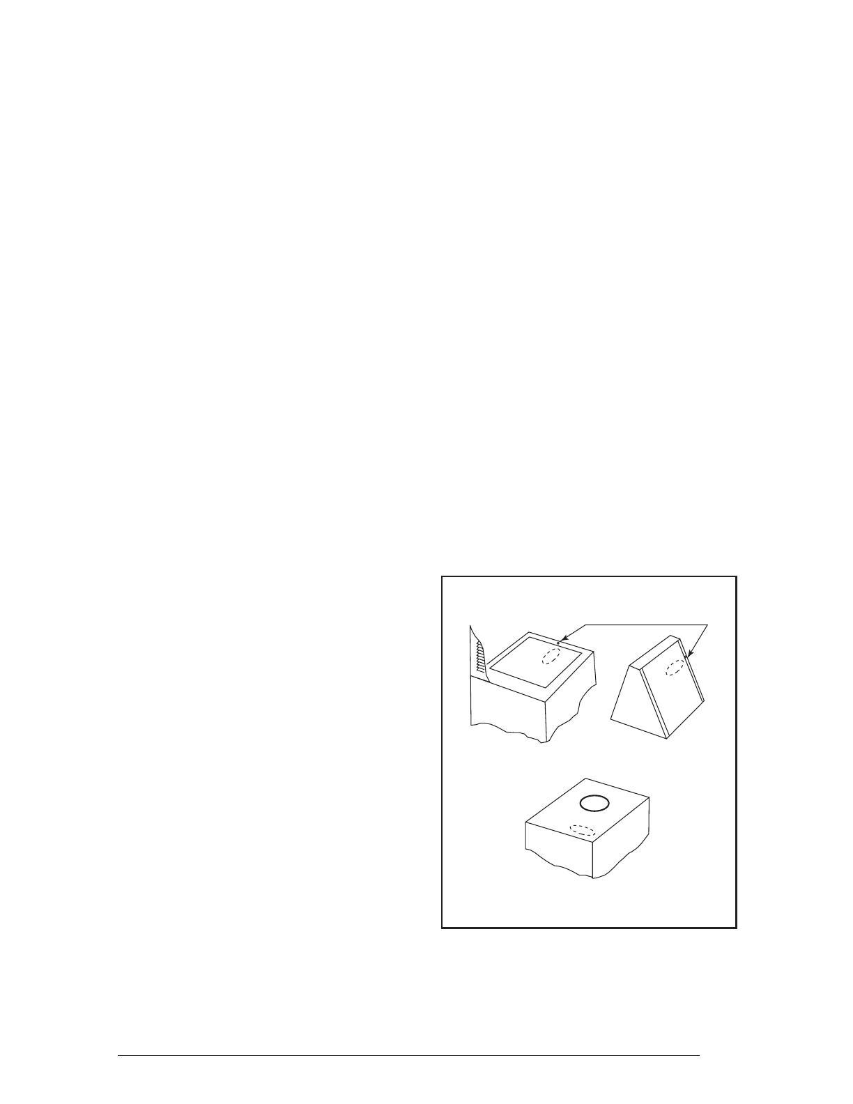
Installation Instructions
DO NOT REMOVE THE OVAL KNOCKOUT
IN FURNACE TOP BEFORE COMPLETING
STEP ONE.
1. Determine the location of the plastic inlet
fi tting.
Gas Furnace (See Figure 1)- Oval knock-
out located at the top, near the front of the
furnace.
Air Handler - Oval knockout located on the
sides of the air handler.
Downfl ow Electric Furnace (see Figure 1)
- The plastic inlet fi tting may be mounted in
the rear of the cabinet over the return air fi lter.
When using an optional air conditioning coil,
it may be mounted to the front or rear coil
end-plate fl ange using the mounting holes
provided.
An optional VentilAire Attachment Kit may
be purchased to attach the plastic inlet
fi tting to the coil or wall in Heat/Cool and
Heat only (no coil) applications. The plastic
inlet fi tting snaps into the Bracket opening
without screws. The kit is Nordyne part
number 919328; bulk kit with 24 brackets
along with fasteners.
Figure 1. Plastic Inlet Fitting Location


