
7930 OPERATING INSTRUCTIONS
Introduction
The 7930 is an asset protection transmitter that can be used to monitor priceless artefacts and works of art, that
are on display and easily accessible. Transmitters can be discreetly placed, without taking away the enjoyment
of viewing interesting historical objects. Movement of the protected item immediately alerts sta or
management ensuring swift and eective action, minimising risk.
Refer to the Iris+ Installation Guide (MK192) for details on adding the device to the system.
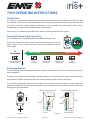
Device application
The unit will respond to acceleration above a pre-set limit in the direction of A, B or C or any combination of the
three (see gure 1).
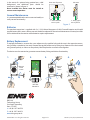
The best way to protect a conventionally mounted painting is to suspend the unit from the underside of the
top horizontal stretcher, slightly away from the vertical stretcher (approx. 5-8mm, see gure 2).
The use of the gold plated suspension springs allow the unit to freely rotate and allows a certain amount of
protection from natural vibrations. When the picture is disturbed the unit bumps against the side or front and
will trigger an alarm condition.
The 7930 transmitter is dispatched down powered to save battery life.
The unit has 3 internal switches. Switch 1 determines device power (on or o),
whilst switches 2 and 3 control the device’s sensitivity. Available settings are
shown below:
Transmitter Powering & Sensitivity
= device power o
(Switch 1 OFF)
Low
sensitivity
High
sensitivity
Medium / high
sensitivity
Medium / low
sensitivity
Figure 1
A
B
C
Figure 2
Rear view of picture frame
5 - 8mm gap
to side
Frame
Side view of picture frame
Canvas
5 - 8mm gap to
rear of picture
Wall
Frame
Least sensitive Most sensitive
As
despatched
7930
PENDANT TRANSMITTER
EN300 220-3
7930
PENDANT TRANSMITTER
EN300 220-3
7930
PENDANT TRANSMITTER
EN300 220-3
©2018 EMS Ltd. All rights reserved Page 1 of 2 TSD217 (Iss 6) 26/07/2018 AJM

In the event of a picture being painted on a solid
background, two additional posts should be
mounted as shown in gure 3.
Once installed the device must be tested to
ensure correct operation.
General Maintenance
It is recommended that the units are tested weekly to
verify correct functionality.
Batteries
The pendant transmitter is supplied with 2 x 1/3 N Lithium Manganese (Li-Mn) Duracell batteries and should
provide battery life in excess of one year and should be replaced on the annual maintenance. A battery low fault
will be indicated at the receiver when batteries require replacement.
Battery Replacement
To replace the batteries, remove the screw adjacent to the necklet hole, and the two in the opposite corners,
using a Philips screwdriver (size zero). Remove the top half of the case by lifting it up. Batteries must be inserted
using correct polarity as shown on the polarity label. Replace the case and screw together.
The device must be retested to guarantee correct battery tting and device functionality.
1. 3.
Replace
three
screws
Remove
three
screws
4.
EMS Ltd.
Technology House
Sea Street, Herne Bay,
Kent, CT6 8JZ.
t: +44 (0) 1227 369570
f: +44 (0) 1227 369679
www.emsgroup.co.uk
Rear view of picture
5 - 8mm between
sensor & pads
Figure 3
Side view
5 - 8mm gap to
rear of picture
7930
PENDANT TRANSMITTER
EN300 220-3
7930
PENDANT TRANSMITTER
EN300 220-3
7930
PENDANT TRANSMITTER
EN300 220-3
7930
PENDANT TRANSMITTER
EN300 220-3
+ -
+ -
OBSERVE
BATTERY
POLARITY!
2.
©2018 EMS Ltd. All rights reserved Page 2 of 2 TSD217 (Iss 6) 26/07/2018 AJM
-
 1
1
-
 2
2


Ask a question and I''ll find the answer in the document
Finding information in a document is now easier with AI
Related papers
-
EMS 7941 Eight Input Transmitter User manual
-
-
-
-
-
-
-
-
-
Other documents
-
Traxxas Aton Plus User manual
-
Appro CV-7930S Operating instructions
-
Scheppach Molda 5.0f Translation From Original Manual
-
Moen 67900 User manual
-
Sony BVP-900P Series Product Information Manual
-
Lincoln Electric LN-7 Operating instructions
-
-
Kenwood MC-85 User manual
-
Raymarine Apelco DXL-6100 User manual
-