VI 1100 CW

PowerWalker VI 1100 CW Quick start guide

  • Hello! I am an AI chatbot trained to assist you with the PowerWalker VI 1100 CW Quick start guide. I’ve already reviewed the document and can help you find the information you need or explain it in simple terms. Just ask your questions, and providing more details will help me assist you more effectively!
ENGLISH
Quick Guide
PowerWalker VI CW Series
I. Setup Requirements
1. Leave sufficient space around for air circulation (recommended 10cm in front, 30cm
in the back and 30cm on sides)
2. Keep ambient temperature below 40ºC. Between 40-50ºC the UPS will gradually
derate the maximal Power reaching 70% at maximal 50ºC.
3. Install the UPS at maximum altitude of 1000m. Between 1000-5000m the UPS will
gradually derate the maximal Power reaching 65% at 5000m.
II. LCD Panel
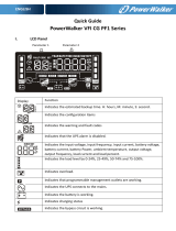
Display
Function
Indicates the estimated backup time. H: hours, M: minute, S: second.
Indicates the configuration items
Indicates the warning and fault codes
Indicates that the UPS alarm is disabled.
Indicates the input voltage, input frequency, input current, battery voltage,
battery current, battery Power, ambient temperature, output voltage,
output frequency, load current and load percent.
Indicates the load level by 0-24%, 25-49%, 50-74% and 75-100%.
Indicates overload.
Indicates that programmable management outlets are working.
Indicates the UPS connects to the mains.
Parameter 1 Parameter 2
ENGLISH
Indicates the battery is working.
Indicates charging status
Indicates the UPS is working in boost mode (AVR activated)
Indicates the UPS is working in buck mode (AVR activated)
Indicates the ECO mode is enabled.
Indicates the AC to DC circuit is working.
Indicates the inverter circuit is working.
Indicates the output is working.
Indicates the battery level by 0-24%, 25-49%, 50-74%, and 75-100%.
Indicates low battery.
III. Rear panel view
1100/1500 VA
1. Programmable outlets:
connect to non-critical loads.
2.
Standard outlets:
connect to mission-critical loads.
3. AC input
4. “Emergency Power Off” connector (EPO)
5. USB communication port
6. RS-232 communication port
7. SNMP intelligent slot
8. Battery Pack connector **
ENGLISH
IV. Communication ports
USB port
RS-232 port
Intelligent slot
Apart from standard USB Port, the UPS is equipped with RS-232. Those two ports do not work
at the same time.
V. Modes and warnings
Warning
Icon
Alarm
Mutable
ECO mode
No Alarm N/A
Boost Mode (AVR)
No Alarm N/A
Buck Mode (AVR)
No Alarm N/A
Battery mode
Sounding every 10
seconds
Yes
Standby mode
No Alarm N/A
Fault Mode
Sounding continuously
N/A
Low Battery
Sounding every 2 seconds
No
Overload (Error 43)
Sounding every second
No
Over input current
Sounding 2 beep every 10
seconds
No
Battery is not
connected
Sounding every 2 seconds
No
Battery Over Charge
(Error 27)
Sounding every 2 seconds
No
ENGLISH
Site wiring fault
Sounding every 2 seconds
No
EPO enabled
Sounding every 2 seconds
No
Over temperature
(Error 41)
Sounding every 2 seconds
No
Charger failure
(Error 45)
Sounding every 2 seconds
No
Battery fault
Sounding every 2 seconds
(UPS remains off to
enforce the battery
check)
No
Battery replacement
Sounding every 2 seconds
No
EEPROM error
Sounding every 2 seconds
No
VI. Button operation
ON/Mute Button
Press and hold ON/Mute button for at least 2 seconds to turn on the UPS.
When the UPS is on battery mode, press and hold this button for at least 3 seconds to
disable or enable the alarm system. But it’s not applied to the situations when warnings
or errors occur.
Press this button to display previous selection in UPS setting mode (up key)
Press and hold ON/Mute button for 3 seconds to enter UPS self-testing while in AC
mode, ECO mode, or converter mode.
OFF/Enter Button
Press and hold this button at least 2 seconds to turn off the UPS. UPS will be in standby
mode under power normal or transfer to “Bypass” mode if the “Bypass enabled” setting
is activated.
Press this button to confirm selection in UPS setting mode.
Select Button
Press this button to change the LCD message for input voltage, input frequency, battery
voltage, output voltage and output frequency.
Press and hold this button for 3 seconds to enter UPS setting mode when UPS is in
standby mode or “bypass” mode.
Press this button to display next selection in UPS setting mode. (down key)
ON/Mute + Select Button
When the input power is normal, press the two buttons simultaneously for 3 seconds.
Then UPS will enter to the bypass” mode. This action will be ineffective when the input
voltage is out of acceptable range.
In setting mode, press the two buttons simultaneously for 0.2s to exit the setting mode.
ENGLISH
VII. UPS Settings
Parameter 1
Parameter 2
01
Output voltage setting
208/220
/230/240
Value in V AC
02
Programmable outlets
ENA/dIS
Enable or Disable (default).
03
Settings of programmable outlets
0-999
Backup time limit for programmable outlets
(default 999)
04
This is reserved position, changing the value will not have any effect
06
Limitation setting for autonomy time
0-999/dIS
Limit in minutes; 0 actually means 10s
07
This is reserved position, changing the value will not have any effect
08
EPO logic setting
AO
Normally Open (default). EPO will be activated
if pins 1 and 2 are not shorted
AC
Normally Closed. EPO will be activated if pins 1
and 2 are shorted
00
Exit Settings
VIII. Programmable Outlets
The settings can be only changed in Standby Mode. After you setting the time limit, Exit the
Settings (Menu 00) and disconnect input, wait until it shuts off completely. Settings will be
saved after the UPS is turned on again.
IX. Site Wiring Fault
“Site Wiring Fault” can be disabled via software. Please check software manual for details.
X. Technical Specification
MODEL
VI 1100 CW
VI 1500 CW
VI 2000 CW
VI 3000 CW
POWER*
1100VA/770W
1500VA/1050W
2000VA/1400W
3000VA / 2100W
INPUT
Acceptable Voltage
162-290 VAC
Frequency Range
50/60 Hz ± 5 Hz (auto sensing)
OUTPUT
Output voltage
208*/220/230/240VAC
AC Voltage
Regulation
± 1.5% (Batt. Mode)
Frequency
Synchronized
Range
47 ~ 53 Hz or 57 ~ 63 Hz
Frequency Range
50 Hz ± 0.1 Hz or 60Hz ± 0.1 Hz (Batt. Mode)
AVR boost/buck
-10%/+16% at 208V; -15%/+10% at 220V;
-15%/+10% at 230V; -15%/+10% at 240V
Current Crest Ratio
3:1
ENGLISH
Harmonic
Distortion
2 % THD (Linear Load) ; 5 % THD (Non-linear Load)
Transfer Time
Typical 2-6 ms, 10ms max.
Waveform
Pure Sinewave
Overload
LINE: 5min @ 103-120%; 10s @ 120-150%; 1s @ >150%
BAT: 1min @ 103-120%; 10s @ 120-150%; 0.5s @ >150%
EFFICIENCY
AC Mode
>96% @ full charged battery
ECO Mode
>97% @ full charged battery
Battery Mode
>88%
>90%
BATTERY
Battery Type
12V/7AH
12V/9AH
12V/7AH
12V/9AH
Numbers
3
6
Recharge Time
4 hours recover to 95% Power for internal battery
Charging Current
1.4 A
Battery Pack**
Battery Pack Connector available **
PHYSICAL
Dimension, D x W x
H
397 X 145 X 220
455 X 145 X 220
Net Weight (kgs)
11.65
12.35
18.1
20.3
ENVIRONMENT
Operation
Humidity
20-95 % RH @ 0- 40°C (non-condensing)
Noise Level
Less than 45dBA @ 1m (with automatic fan speed control)
MANAGEMENT
USB with HID
PowerWalker ViewPower
* Derate Power to 80% of Power when the output voltage is adjusted to 208VAC.
**Derate Power to 70% of Power when Battery Pack is connected
/