RAB Lighting VANLED10 Operating instructions

Category
Motorcycle Accessories
Type
Operating instructions
INSTRUCTIONS
VANLED
®
INSTALLATION
RAB Lighting is committed to creating high-quality, aordable, well-designed and energy-ecient LED lighting and controls that make it easy for electricians to install
and end users to save energy. We’d love to hear your comments. Please call the Marketing Department at 888-RAB-1000 or email: [email protected]
Fig: 1
IMPORTANT
READ CAREFULLY BEFORE INSTALLING FIXTURE. RETAIN THESE INSTRUCTIONS FOR FUTURE REFERENCE.
RAB xtures must be wired in accordance with the National Electrical Code and all applicable local codes. Proper grounding is
required for safety. THIS PRODUCT MUST BE INSTALLED IN ACCORDANCE WITH THE APPLICABLE INSTALLATION CODE BY A PERSON
FAMILIAR WITH THE CONSTRUCTION AND OPERATION OF THE PRODUCT AND THE HAZARDS INVOLVED.
WARNING: Make certain power is OFF before installing or maintaining xture. No user serviceable parts inside.
CAUTION: For proper weatherproof function all gaskets must be seated properly and all screws inserted and tightened
rmly. Apply weatherproof silicone sealant around the edge of the Ceiling Mounting Box and/or Junction Box. This is
especially important with an uneven ceiling surface. Silicone all plugs and unused conduit entries.
CEILING MOUNTING
The xture is suitable for outdoor applications in wet locations.
1. Remove Door by loosening (4) Captive Screws.
2. Remove Reector/ LED Assembly by loosening (4) Reector/
LED Screws.
3. Hang Reector/ LED Assembly by Tether Cable.
4. Knock out appropriate Slots as marked in Fig. 2, by loosening
Screws (2) on Access Plate and secure to junction box (not
supplied). Check gasket is fully sealed.
5. Mount Ceiling Mounting Box to ceiling by drilling out (4) Drill
Locations as marked in Fig. 2. Use the appropriate mounting
hardware for the mounting surface. Be sure gasket is properly
seated.
6. Feed xture wires through the Access Plate or through one
of the Plugs (4) to make electrical splices in junction box. Use
appropriate UL approved wire connectors as required by code to
complete wiring.
7. Re-assemble Reector/ LED Assembly and Door. Be careful not
to pinch wires.
8. Tighten all screws.
9. Use silicone or teon tape on all Plugs and on the threads of all
conduit entry points. If outdoor surface is irregular , use caulk to
seal any gaps around Ceiling Mounting Box.
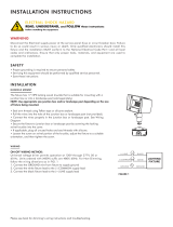
VANLED - Drop Lens
VANLED - Flat Lens
Plugs (4)
Access Plate
Screws (2)
Tether Cable
Reector/ LED
Assembly
Reector/ LED
Screws (4)
Captive
Screws (4)
Door
Ceiling Mounting Box
INSTRUCTIONS
VANLED
®
INSTALLATION
RAB Lighting is committed to creating high-quality, aordable, well-designed and energy-ecient LED lighting and controls that make it easy for electricians to install
and end users to save energy. Wed love to hear your comments. Please call the Marketing Department at 888-RAB-1000 or email: [email protected]
DRILL LOCATION
Fig. 2
010V DIMMABLE WIRING
CLEANING & MAINTENANCETROUBLESHOOTING
Note: These instructions do not cover all details or variations in equipment nor do they provide for every possible situation during installation, operation or maintenance.
Universal voltage driver permits operation at 120V thru 277V, 50 or
60 Hz. Units ordered with (/480V) sux are 480V, 50Hz or 60Hz. For
0-10V Dimming, follow the wiring directions in g. 4.
1. Connect the black xture lead to the (+) LINE supply lead.
2. Connect the white xture lead to the (-) COMMON supply lead.
3. Connect the GROUND wire from xture to supply ground. Do
NOT connect the GROUND of the dimming xture to the output.
4. Connect the purple xture lead to the (V+) DIM lead.
5. Connect the gray xture lead to the (V-) DIM lead.
6. Cap the yellow xture lead, if present. Do NOT connect.
Fig. 4
CAUTION: Be sure xture temperature is cool enough to touch.
Do not clean or maintain while xture is energized.
1. Clean polycarbonate lens with non-abrasive cleaning solution.
2. Do not open the xture to clean the LEDs. Do not touch the
LEDs.
1. Check that the line voltage at the xture is correct. Refer to
wiring directions.
2. Be sure the xture is grounded properly.
3. Is the photocell, if used, functioning properly?
1 3/8”
[34mm]
10 1/8”
[257mm]
11 1/2”
[291mm]
2”
[53mm]
10”
[255mm]
11 1/2”
[291mm]
2 1/4”
[58mm]
9”
[228mm]
Drill Location (4)
Slot
VANLED IN 1019
Easy Answers
rablighting.com
Visit our website for product info
Tech Help Line
Call our experts: 888 722-1000
e-mail
Answered promptly - [email protected]
Free Lighting Layouts
Answered online or by request
© 2019 RAB LIGHTING Inc.
Northvale, New Jersey 07647 USA
RAB WARRANTY: RAB’s warranty is subject to all terms and conditions found at rablighting.com/warranty. Patent: rablighting.com/ip
73141-RAB
  • Page 1 1
  • Page 2 2

RAB Lighting VANLED10 Operating instructions

Category
Motorcycle Accessories
Type
Operating instructions

Ask a question and I''ll find the answer in the document

Finding information in a document is now easier with AI