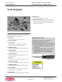
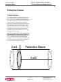
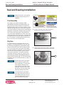
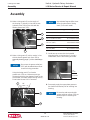
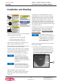
Helac L10-3.0 is a hydraulic rotary actuator designed to convert linear piston motion into powerful shaft rotation. With its compact design, exceptional load bearing capabilities, and rugged, reliable performance, it's ideal for various applications, including:
- Utility aerials (basket rotation)
- Rock drills (drill rod magazine rotation)
- Industrial vehicles (steering)
- Robotic equipment (joint movement) and jib cranes (boom rotation)
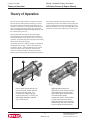
The L10-3.0 features a simple mechanism with only two moving parts, ensuring smooth and efficient operation.
- The housing with an integral ring gear remains stationary.
Helac L10-3.0 is a hydraulic rotary actuator designed to convert linear piston motion into powerful shaft rotation. With its compact design, exceptional load bearing capabilities, and rugged, reliable performance, it's ideal for various applications, including:
- Utility aerials (basket rotation)
- Rock drills (drill rod magazine rotation)
- Industrial vehicles (steering)
- Robotic equipment (joint movement) and jib cranes (boom rotation)
The L10-3.0 features a simple mechanism with only two moving parts, ensuring smooth and efficient operation.
- The housing with an integral ring gear remains stationary.


-
 1
1
-
 2
2
-
 3
3
-
 4
4
-
 5
5
-
 6
6
-
 7
7
-
 8
8
-
 9
9
-
 10
10
-
 11
11
-
 12
12
-
 13
13
-
 14
14
-
 15
15
-
 16
16
-
 17
17
-
 18
18
-
 19
19
-
 20
20
-
 21
21
-
 22
22
-
 23
23
-
 24
24
-
 25
25
-
 26
26
-
 27
27
-
 28
28
-
 29
29
-
 30
30
-
 31
31
-
 32
32


Helac L10-3.0 Service & Repair Manual
- Type
- Service & Repair Manual
Helac L10-3.0 is a hydraulic rotary actuator designed to convert linear piston motion into powerful shaft rotation. With its compact design, exceptional load bearing capabilities, and rugged, reliable performance, it's ideal for various applications, including:
- Utility aerials (basket rotation)
- Rock drills (drill rod magazine rotation)
- Industrial vehicles (steering)
- Robotic equipment (joint movement) and jib cranes (boom rotation)
The L10-3.0 features a simple mechanism with only two moving parts, ensuring smooth and efficient operation.
- The housing with an integral ring gear remains stationary.
Ask a question and I''ll find the answer in the document
Finding information in a document is now easier with AI
Other documents
-
PowerBoss L10 Owner's manual
-
Ekena Millwork BKTM02X16X01HFPBL Operating instructions
-
Ekena Millwork BKTM02X10X01HFPBL Operating instructions
-
Sunnydaze Decor PL-694 Operating instructions
-
Dataflex 52.312 Datasheet
-
MAC TOOLS AWD099-S User manual
-
Home Decorators Collection 3808810220 Installation guide
-
Parker IBS3100FX User manual
-
Parker Hannifin VO40 User manual
-