Grizzly T31999 Owner's manual
- Category
- Power universal cutters
- Type
- Owner's manual

COPYRIGHT © MARCH, 2020 BY GRIZZLY INDUSTRIAL, INC.
WARNING: NO PORTION OF THIS MANUAL MAY BE REPRODUCED IN ANY SHAPE
OR FORM WITHOUT THE WRITTEN APPROVAL OF GRIZZLY INDUSTRIAL, INC.
#KS20992 PRINTED IN CHINA
MODEL T31999
BISCUIT JOINER
OWNER'S MANUAL
(For models manufactured since 02/20)
V1.03.20

This manual provides critical safety instructions on the proper setup,
operation, maintenance, and service of this machine/tool. Save this
document, refer to it often, and use it to instruct other operators.
Failure to read, understand and follow the instructions in this manual
may result in fire or serious personal injury—including amputation,
electrocution, or death.
The owner of this machine/tool is solely responsible for its safe use.
This responsibility includes but is not limited to proper installation in
a safe environment, personnel training and usage authorization,
proper inspection and maintenance, manual availability and compre-
hension, application of safety devices, cutting/sanding/grinding tool
integrity, and the usage of personal protective equipment.
The manufacturer will not be held liable for injury or property damage
from negligence, improper training, machine modifications or misuse.
Some dust created by power sanding, sawing, grinding, drilling, and
other construction activities contains chemicals known to the State
of California to cause cancer, birth defects or other reproductive
harm. Some examples of these chemicals are:
• Lead from lead-based paints.
• Crystalline silica from bricks, cement and other masonry products.
• Arsenic and chromium from chemically-treated lumber.
Your risk from these exposures varies, depending on how often you
do this type of work. To reduce your exposure to these chemicals:
Work in a well ventilated area, and work with approved safety equip-
ment, such as those dust masks that are specially designed to filter
out microscopic particles.

Table of Contents
SECTION 1: SAFETY .......................................................................................................2
Additional Safety for Biscuit Joiners ...........................................................................4
SECTION 2: INTRODUCTION .........................................................................................5
Foreword .....................................................................................................................5
Contact Info ................................................................................................................5
Machine Data Sheet ...................................................................................................6
Identification ................................................................................................................7
Controls & Components .............................................................................................8
SECTION 3: POWER SUPPLY ........................................................................................9
SECTION 4: SETUP .......................................................................................................11
Unpacking .................................................................................................................11
Inventory ...................................................................................................................12
Assembly ..................................................................................................................13
Dust Collection ..........................................................................................................13
Test Run ...................................................................................................................14
SECTION 5: OPERATIONS ...........................................................................................15
Adjusting Depth of Cut..............................................................................................15
Adjusting Cutting Angle ............................................................................................16
Adjusting Cutting Height ...........................................................................................17
Workpiece Preparation .............................................................................................18
Cutting Biscuit Grooves ............................................................................................19
Gluing Biscuits ..........................................................................................................19
Changing Blade ........................................................................................................20
SECTION 6: ACCESSORIES .........................................................................................22
SECTION 7: MAINTENANCE ........................................................................................23
Cleaning ....................................................................................................................23
Lubrication ................................................................................................................23
Replacing Brushes ....................................................................................................24
SECTION 8: SERVICE ...................................................................................................25
Troubleshooting ........................................................................................................25
SECTION 9: PARTS .......................................................................................................26
Main ..........................................................................................................................26
Labels & Cosmetics ..................................................................................................28
WARRANTY & RETURNS .............................................................................................29

For Your Own Safety Read Instruction Manual
Before Operating This Equipment
The purpose of safety symbols is to attract your attention to possible hazard-
ous conditions. This manual uses a series of symbols and signal words which
are intended to convey the level of importance of the safety messages. The
progression of symbols is described below. Remember that safety messages by
themselves do not eliminate danger and are not a substitute for proper accident
prevention measures.
Indicates an imminent hazardous situation which, if
not avoided, WILL result in death or serious injury.
Indicates a potentially hazardous situation which, if
not avoided, COULD result in death or serious injury.
Indicates a potentially hazardous situation which, if
not avoided, MAY result in minor or moderate injury.
It may also be used to alert against unsafe practices.
This symbol is used to alert the user to useful infor-
mation about proper operation of the equipment.
NOTICE
Safety Instructions for Power Tools
OWNER’S MANUAL. Read and under-
stand this owner’s manual BEFORE using
machine.
TRAINED OPERATORS ONLY. Untrained
operators have a higher risk of being hurt
or killed. Only allow trained/supervised
people to use this power tool. When tool
is not being used, disconnect power, and
store in out-of-reach location to prevent
unauthorized use—especially around
children. Make workshop kid proof!
DANGEROUS ENVIRONMENTS. Do not
use tools in areas that are wet, cluttered,
or have poor lighting. Operating tools in
these areas greatly increases risk of acci-
dents and injury.
MENTAL ALERTNESS REQUIRED. Full
mental alertness is required for safe oper-
ation of power tools. Never operate under
the influence of drugs or alcohol, when
tired, or when distracted.
DISCONNECT POWER FIRST. Always
disconnect tool from power supply
BEFORE making adjustments, changing
tooling, or servicing machine. This pre-
vents an injury risk from unintended startup
or contact with live electrical components.
EYE PROTECTION. Always wear ANSI-
approved safety glasses or a face shield
when operating or observing machinery to
reduce the risk of eye injury or blindness
from flying particles. Everyday eyeglasses
are not approved safety glasses.
Model T31999 (Mfd. Since 02/20)-2-
SECTION 1: SAFETY

ELECTRICAL SAFETY. Tool plug must
match outlet. Double-insulated tools have
a polarized plug (one blade is wider than
the other), which must be plugged into a
polarized outlet. Never modify plug. Do
not use adapter for grounded tools. Use
a ground fault circuit interrupter if opera-
tion is unavoidable in damp locations.
Avoid touching grounded surfaces when
operating tool.
WEARING PROPER APPAREL. Do not
wear clothing, apparel or jewelry that
can become entangled in moving parts.
Always tie back or cover long hair. Wear
non-slip footwear to avoid accidental
slips, which could cause loss of workpiece
control. Wear hard hat as needed.
HAZARDOUS DUST. Dust created while
using tools may cause cancer, birth
defects, or long-term respiratory damage.
Be aware of dust hazards associated with
each workpiece material, always wear
a NIOSH-approved respirator, and con-
nect tool to an appropriate dust collection
device to reduce your risk.
HEARING PROTECTION. Always wear
hearing protection when operating or
observing loud machinery. Extended
exposure to this noise without hearing
protection can cause permanent hearing
loss.
REMOVE ADJUSTING TOOLS. Never
leave adjustment tools, chuck keys,
wrenches, etc. in or on tool—especially
near moving parts. Verify removal before
starting!
INTENDED USAGE. Only use tool for its
intended purpose. Never modify or alter
tool for a purpose not intended by the
manufacturer or serious injury or death
may result!
AWKWARD POSITIONS. Keep proper
footing and balance at all times when
operating tool. Do not overreach! Avoid
awkward hand positions that make tool
control difficult or increase the risk of
accidental injury.
SAFE HANDLING. Firmly grip tool. To
avoid accidental firing, do not keep finger
on switch or trigger while carrying.
FORCING TOOLS.. Use right tool for job,
and do not force it. It will do job safer and
better at rate for which it was designed.
SECURING WORKPIECE. When
required, use clamps or vises to secure
workpiece. This protects hands and frees
both of them to operate tool.
GUARDS & COVERS. Guards and cov-
ers reduce accidental contact with mov-
ing parts or flying debris. Ensure they
are properly installed, undamaged, and
working correctly.
CHILDREN & BYSTANDERS. Keep chil-
dren and bystanders at a safe distance
from the work area. Stop using tool if they
become a distraction.
USE RECOMMENDED ACCESSORIES.
Consult this manual or manufacturer
for recommended accessories. Using
improper accessories will increase risk of
serious injury.
MAINTAIN WITH CARE. Keep cutting
tool edges sharp and clean. Follow all
maintenance instructions and lubrication
schedules to keep tool in good work-
ing condition. A tool that is improperly
maintained could malfunction, leading to
serious personal injury or death. Only
have tool serviced by qualified service-
personnel using matching replacement
parts.
CHECK DAMAGED PARTS. Regularly
inspect tool for any condition that may
affect safe operation. Immediately repair
or replace damaged or mis-adjusted parts
before operating tool.
MAINTAIN POWER CORDS. When dis-
connecting cord-connected tools from
power, grab and pull the plug—NOT the
cord. Carrying or pulling the cord may
damage wires inside. Do not handle cord/
plug with wet hands. Avoid cord damage
by keeping it away from heated surfaces,
high traffic areas, harsh chemicals, sharp
edges, moving parts, and wet/damp loca-
tions. Damaged cords increase risk of
electrocution.
UNATTENDED OPERATION. Never
leave tool running while unattended. Turn
tool OFF and ensure all moving parts
completely stop before walking away.
EXPERIENCING DIFFICULTIES.
If at
any time you experience difficulties per-
forming the intended operation, stop
using the machine! Contact our Technical
Support at (570) 546-9663.
Model T31999 (Mfd. Since 02/20) -3-

No list of safety guidelines can be
complete. Every shop environment
is different. Always consider safety
first, as it applies to your individual
working conditions. Use this and
other machinery with caution and
respect. Failure to do so could result
in serious personal injury, damage
to equipment or poor work results.
Like all machinery there is potential
danger when operating this tool.
Accidents are frequently caused by
lack of familiarity or failure to pay
attention. Use this tool with respect
and caution to decrease the risk of
operator injury. If normal safety pre-
cautions are overlooked or ignored,
serious personal injury may occur.
Model T31999 (Mfd. Since 02/20)-4-
Additional Safety for Biscuit Joiners
USE RECOMMENDED BLADES. Only
use blades rated for speeds greater than
11,000 RPM. Blades not rated for this
speed may fly apart. Only use blades that
meet the specifications listed in the manu-
al. Do not use blades with different diam-
eters or arbor hole shapes/sizes. They will
rotate irregularly, causing ejection of blade
fragments and tool damage.
PROPERLY INSTALL COMPONENTS.
Ensure sliding base, faceplate, and fence
are in place and operating correctly before
each cut.
STARTING AND STOPPING CUTS.
Allow blade to reach full speed before
cutting. Always allow blade to come to a
complete stop before setting tool down.
MAINTAIN CONTROL OF TOOL. Hold
tool with both hands and do not allow the
Biscuit Joiner base to shift while perform-
ing plunge cuts.
Serious cuts, amputation, or death can occur from contact with rotating saw
blade during operation. Workpieces, broken blades, or flying particles thrown
by blade can blind or strike operators or bystanders with great force. To reduce
the risk of these hazards, operator and bystanders MUST completely heed the
hazards and warnings below.
PROPERLY MAINTAIN BLADE. Always
ensure Biscuit Joiner blade is sharp,
undamaged, and tightly attached before
each use.
AVOID TOUCHING BLADE. Never
place hands or fingers between work-
piece and blade, and do not perform a
cut while supporting workpiece with one
hand or balancing it on a leg or any other
body part.
PROPERLY SUPPORT WORKPIECE.
Properly support all workpieces to reduce
risk of workpiece and tool slipping during
cutting operation. Place workpiece on
supports or workbench and clamp in
place.
USE BISCUIT JOINER FOR INTENDED
PURPOSE. Only use Biscuit Joiner on
wood and wood-based products. Do not
attempt to use this tool for any operation
other than biscuit joining.

Contact Info
We stand behind our machines! If you have
questions or need help, contact us with the
information below. Before contacting, make
sure you get the
serial number and
manu-
facture date from the machine ID label. This
will help us help you faster.
Grizzly Technical Support
1815 W. Battlefield
Springfield, MO 65807
Phone: (570) 546-9663
Email: [email protected]
We want your feedback on this manual.
What did you like about it? Where could it
be improved? Please take a few minutes to
give us feedback.
Grizzly Documentation Manager
P.O. Box 2069
Bellingham, WA 98227-2069
Email: [email protected]
Model T31999 (Mfd. Since 02/20) -5-
SECTION 2: INTRODUCTION
We are proud to offer this manual with your
new Model T31999 Biscuit Joiner! We've
made every effort to be exact with the
instructions, specifications, drawings, and
photographs of the joiner we used when
writing this manual. However, sometimes
we still make an occasional mistake.
Also, owing to our policy of continuous
improvement, your biscuit joiner may not
exactly match the manual. If you find this
to be the case, and the difference between
the manual and the joiner leaves you in
doubt, check our website for the latest
manual update or call technical support
for help.
For your convenience, we post all avail-
able manuals and manual updates for free
on our website at www.grizzly.com. Any
updates to your model of machine will be
reflected in these documents as soon as
they are complete.
Foreword

Page 1 of 2 Model T31999
MODEL T31999
BISCUIT JOINER
Customer Service #: (570) 546-9663 · To Order Call: (800) 523-4777 · Fax #: (800) 438-5901
Product Dimensions:
Weight ������������������������������������������������������������������������������������������������������������������������������������������������������������������������������� 6 lbs�
Width (side-to-side) x Depth (front-to-back) x Height �������������������������������������������������������������������������������������18 x 5-1/2 x 6 in�
Shipping Dimensions:
Type ������������������������������������������������������������������������������������������������������������������������������������������������������������������� Cardboard Box
Content �������������������������������������������������������������������������������������������������������������������������������������������������������������������������� Machine
Weight �������������������������������������������������������������������������������������������������������������������������������������������������������������������������������� 8 lbs�
Length/Width/Height �����������������������������������������������������������������������������������������������������������������������������������������������15 x 6 x 7 in�
Electrical:
Power Requirement ������������������������������������������������������������������������������������������������������������������������ 120V, Single-Phase, 60 Hz
Full-Load Current Rating ����������������������������������������������������������������������������������������������������������������������������������������������������� 5�9A
Minimum Circuit Size ����������������������������������������������������������������������������������������������������������������������������������������������������������� 15A
Connection Type ����������������������������������������������������������������������������������������������������������������������������������������������������� Cord & Plug
Power Cord Included ������������������������������������������������������������������������������������������������������������������������������������������������������������Yes
Power Cord Length �������������������������������������������������������������������������������������������������������������������������������������������������������������10 ft�
Power Cord Gauge ������������������������������������������������������������������������������������������������������������������������������������������������������� 18 AWG
Plug Included ������������������������������������������������������������������������������������������������������������������������������������������������������������������������
Yes
Included Plug Type �������������������������������������������������������������������������������������������������������������������������������������������������� NEMA 1-15
Switch Type ������������������������������������������������������������������������������������������������������������������������������������������ ON/OFF Toggle Switch
Motor:
Horsepower �������������������������������������������������������������������������������������������������������������������������������������������������������������������������1 HP
Phase �������������������������������������������������������������������������������������������������������������������������������������������������������������������� Single-Phase
Amps ����������������������������������������������������������������������������������������������������������������������������������������������������������������������������������� 5�9A
Speed ����������������������������������������������������������������������������������������������������������������������������������������������������������������������11,600 RPM
Type �����������������������������������������������������������������������������������������������������������������������������������������������������������������������������Universal
Power Transfer �������������������������������������������������������������������������������������������������������������������������������������������������������������������Gear
Bearings ����������������������������������������������������������������������������������������������������������������������������� Shielded & Permanently Lubricated
Main Specifications:
Operation Info
Maximum Cutting Depth ��������������������������������������������������������������������������������������������������������������������������������������23/32 in�
Maximum Cutting Height �����������������������������������������������������������������������������������������������������������������������������������������3/4 in�
Fence Tilt Angle ��������������������������������������������������������������������������������������������������������������������������������������������� 0 – 90 deg�
Blade Diameter �����������������������������������������������������������������������������������������������������������������������������������������������������������4 in�
Blade Thickness ����������������������������������������������������������������������������������������������������������������������������������������������������5/32 in�
Arbor Size �����������������������������������������������������������������������������������������������������������������������������������������������������20mm/22mm
Model T31999Page 2 of 2
Other
Number of Dust Ports ������������������������������������������������������������������������������������������������������������������������������������������������������1
Dust Port Size ������������������������������������������������������������������������������������������������������������������������������������������������������������1 in�
Other Specifications:
Country Of Origin �������������������������������������������������������������������������������������������������������������������������������������������������������������� China
Warranty ��������������������������������������������������������������������������������������������������������������������������������������������������������������������������� 1 Year
Approximate Assembly & Setup Time ���������������������������������������������������������������������������������������������������������������������� 20 Minutes
Serial Number Location ������������������������������������������������������������������������������������������������������������������������������������������������
ID Label
Features:
Includes 4" 6T Blade
Accepts 4" Blades with 20mm or 22mm Bore
Adjustable Depth Stop with Maximum Cutting Depth of 23/32"
Removable Fence with Cutting-Height Adjustment of 0 – 1-9/16"
Cutting Angle of 0º – 90° with Stops at 0°, 45°, and 90°
Six-Position Turret Stop for Biscuit Depth (0, 10, 20, S, D, and MAX)
Hinged Base for Easy Blade Removal
Dust Extraction Through Blade Housing
Accessories:
Dust Collection Bag with Adapter
6mm Hex Wrench
Flange Wrench
Two Replacement Motor Brushes
75 Assorted Biscuits
Model T31999 (Mfd. Since 02/20)-6-

To reduce your risk of
serious injury, read
this entire manual
BEFORE using tool.
Model T31999 (Mfd. Since 02/20) -7-
Identification
Become familiar with the names and locations of the controls and features shown below to
better understand the instructions in this manual.
Spindle
Lock
Button
Fence
Lock
Knob
Angle
Scale
ON/OFF
Switch
Dust
Port
Dust
Bag
Sliding
Base
Depth
Indicator
Depth
Stop
Faceplate
Fence
Angle
Lock
Fence
Height
Scale
Fence
Auxiliary Handle
Blade Access Knob

To reduce your risk of
serious injury, read this
entire manual BEFORE
using machine.
Figure 1. Fence adjustment and power
controls.
Figure 2. Depth adjustment, angle lock,
and dust port.
Model T31999 (Mfd. Since 02/20)-8-
Controls &
Components
Refer to Figures 1 & 2 and the following
descriptions to become familiar with the
basic controls of this tool.
A. Spindle Lock Button: When pressed,
locks spindle for removing/replacing
blade.
B. Fence Lock Knob: Locks fence at
desired height of cut.
C. Fence: Orients tool to workpiece at
specified angle.
D. Fence Height Scale: Indicates dis-
tance between center of blade and
bottom of fence.
E. Angle Scale: Indicates angle of cut.
F. ON/OFF Switch: Starts and stops
motor. Tool will remain running while
switch is held until released.
G
. Dust Port: Connects dust extraction
system to blade housing and prevents
dust build up during cutting operations.
H. Sliding Base: Houses blade. Spring
action retracts blade after cut.
I. Depth Stop: Contacts turret stop dur-
ing operation, limiting depth of cut.
J. Depth Indicator: Six-position turret for
selecting biscuit cut depth (0, 10, 20, S,
D, and MAX).
K. Faceplate: Contacts edge of workpiece
at desired location of biscuit groove.
L. Angle Lock: Locks faceplate to desired
angle of cut.
D
A
B
C
E
F
G
H
I J
K
L

For your own safety and protection
of property, consult an electrician if
you are unsure about wiring prac-
tices or electrical codes in your area.
Serious injury could occur if you
connect machine to power before
completing setup process. DO NOT
connect to power until instructed
later in this manual.
Electrocution, shock, fire
or damage to equipment
may occur if machine is
not properly grounded
and connected to power
supply.
Model T31999 (Mfd. Since 02/20) -9-
SECTION 3: POWER SUPPLY
Availability
Before installing the machine, consider the
availability and proximity of the required
power supply circuit. If an existing circuit
does not meet the requirements for this
machine, a new circuit must be installed.
To minimize the risk of electrocution, fire,
or equipment damage, installation work
and electrical wiring must be done by an
electrician or qualified service personnel in
accordance with all applicable codes and
standards.
The full-load current rating is the amper-
age a machine draws at 100% of the rated
output power. On machines with multiple
motors, this is the amperage drawn by
the largest motor or sum of all motors and
electrical devices that might operate at
one time during normal operations.
Full-Load Current Rating
.....................5.9A
The full-load current is not the maximum
amount of amps that the machine will draw.
If the machine is overloaded, it will draw
additional amps beyond the full-load rating.
If the machine is overloaded for a sufficient
length of time, damage, overheating, or fire
may result—especially if connected to an
undersized circuit. To reduce the risk of these
hazards, avoid overloading the machine dur-
ing operation and make sure it is connected
to a power supply circuit that meets the
requirements in the following section.
Full-Load Current Rating
Note: The circuit requirements listed in
this manual apply to a dedicated circuit—
where only one machine will be running at
a time. If this machine will be connected to
a shared circuit where multiple machines
will be running at the same time, consult
a qualified electrician to ensure that the
circuit is properly sized for safe operation.
This machine is prewired to operate on a
power supply circuit that has a verified ground
and meets the following requirements:
120V Circuit Requirements
Voltage ..........................110V, 115V, 120V
Cycle ................................................. 60 Hz
Phase ...................................Single-Phase
Power Supply Circuit ................ 15 Amps
A power supply circuit includes all electri-
cal equipment between the breaker box
or fuse panel in the building and the
machine. The power supply circuit used
for this machine must be sized to safely
handle the full-load current drawn from the
machine for an extended period of time.
(If this machine is connected to a circuit
protected by fuses, use a time delay fuse
marked D.)

5-15 Receptacle
1-15 Plug
Neutral
Hot
Figure 3. Typical 1-15 plug and
receptacle.
Model T31999 (Mfd. Since 02/20)-10-
To reduce the risk of electric shock, this
equipment has a polarized plug (one blade
is wider than the other). This plug will fit in
a polarized outlet only one way. If the plug
does not fit fully in the outlet, reverse the
plug. If it still does not fit, contact a quali-
fied electrician to install the proper outlet.
Do not change the plug in any way.
When servicing use only identical replace-
ment parts.
Polarized Plug Extension Cords
When using extension cords, make sure
the cords are rated for outdoor use.
Outdoor use cords are marked with a
"W-A" or a "W" to signify their rating.
Always check to make sure that the exten-
sion cords are in good working order
and free of any type of damage, such as
exposed wires, cuts, creased bends, or
missing prongs.
Extension cords cause voltage drop, which
may damage electrical components and
shorten motor life. Voltage drop increases
as the extension cord size gets longer and
the gauge size gets smaller (higher gauge
numbers indicate smaller sizes. When
using extension cords, always choose the
shortest cord possible, with the greatest-
sized gauge.
Below is a list of minimum gauge sizes
needed for running this tool at different
lengths:
25 Feet .......................................... 16AWG
50 Feet .......................................... 14AWG
100 Feet ........................................ 12AWG
Over 100 Feet ........... Not Recommended

This tool presents serious injury
hazards to untrained users. Read
through this entire manual to
become familiar with the controls
and operations before starting the
tool!
Model T31999 (Mfd. Since 02/20) -11-
SECTION 4: SETUP
This tool was carefully packaged for safe
transport. When unpacking, separate all
enclosed items from packaging materials
and inspect them for shipping damage.
If items are damaged, please call us
immediately at (570) 546-9663.
IMPORTANT: Save all packaging materi-
als until you are completely satisfied with
the tool and have resolved any issues
between Grizzly or the shipping agent. You
MUST have the original packaging to file a
freight claim. It is also extremely helpful if
you need to return the tool later.
Unpacking

If you cannot find an item on this
list, carefully check around/inside
the tool and packaging materials.
Often, these items get lost in pack-
aging materials while unpacking or
they are pre-installed at the factory.
Figure 4. Model T31999 Biscuit Joiner.
Figure 5. Loose inventory.
Model T31999 (Mfd. Since 02/20)-12-
The following is a list of items shipped
with your tool. Before beginning setup, lay
these items out and inventory them.
If any non-proprietary parts are missing
(e.g. a nut or a washer), we will gladly
replace them; or for the sake of expediency,
replacements can be obtained at your
local hardware store.
Box 1 (Figures 4 & 5) Qty
A. Biscuit Joiner ...................................... 1
B. Dust Bag ............................................ 1
C. Fence ................................................. 1
D. Hex Wrench 6mm .............................. 1
E. Motor Brushes .................................... 2
F. Spanner Wrench ................................ 1
D
C
B
F
E
A
Inventory

Figure 7. Installing dust bag into dust port.
Figure 6. Fence attached to faceplate.
Model T31999 (Mfd. Since 02/20) -13-
To assemble tool:
1. Loosen fence lock knob, and slide
fence onto faceplate (see Figure 6).
2. Tighten fence lock knob (see Figure 6).
Fence
Faceplate
Fence
Lock
Knob
Assembly Dust Collection
The Model T31999 is equipped with a 1"
dust port that can attach to a dust collec-
tion system (not included) or the included
dust bag.
To install dust bag:
1. Push plastic end of dust bag into dust
port, as shown in Figure 7.
Dust Port
Dust Bag
2. Verify dust bag is closed before operat-
ing tool.

DO NOT start tool until all preced-
ing setup instructions have been
performed. Operating an improperly
set up tool may result in malfunc-
tion or unexpected results that can
lead to serious injury, death, or tool/
property damage.
Serious injury or death can result
from using tool BEFORE under-
standing its controls and related
safety information. DO NOT oper-
ate, or allow others to operate, tool
until information is understood.
Figure 8. Location of auxiliary handle and
ON/OFF switch.
Model T31999 (Mfd. Since 02/20)-14-
To test run tool:
1. Clear away all setup/adjustment tools.
2. Verify blade is properly installed (see
Changing Blade on Page 20).
3. Connect tool to power supply.
4. While firmly holding auxiliary handle
(see Figure 8) in one hand, squeeze
ON/OFF switch with opposite hand.
Motor should run smoothly and without
unusual problems or noises.
5
. Release ON/OFF switch. Motor should
immediately stop running.
Congratulations! Test run is complete.
ON/OFF
Switch
Auxiliary Handle
Test Run
Once assembly is complete, test run the
tool to ensure it is properly connected to
power and safety components are working
properly.
If you find an unusual problem during the
test run, immediately stop the tool, discon-
nect it from power, and fix the problem
BEFORE operating the tool again. The
Troubleshooting table in the SERVICE
section of this manual can help.
The test run consists of verifying the fol-
lowing: 1) The motor powers up and runs
correctly.

To reduce your risk of
serious injury, read this
entire manual BEFORE
using machine.
If you are not experienced with this
type of tool, WE STRONGLY REC-
OMMEND that you seek additional
training outside of this manual.
Read books/magazines or get for-
mal training before beginning any
projects. Regardless of the content
in this section, Grizzly Industrial
will not be held liable for accidents
caused by lack of training.
To reduce risk of eye injury from
flying chips or lung damage from
breathing dust, always wear safety
glasses and a respirator when oper-
ating this tool.
Biscuit # Material
Thickness
(mm)
Cut
Depth
(mm)
Depth
Indicator
Marking
#0 4 8 0
#10 4 10 10
#20 4 12.5 20
Simplex 4 13 S
Duplex 4 15 D
N/A N/A 18 MAX
Figure 9. Biscuit cut depth and depth
scale marking table.
Figure 10. Depth indicator aligned with
arrow mark.
Model T31999 (Mfd. Since 02/20) -15-
SECTION 5: OPERATIONS
Adjusting Depth of Cut
The biscuit joiner can be adjusted to cut
slots for standard #0, #10 and #20 biscuits,
simplex fittings, and duplex hinges. Refer
to the table in Figure 9 to determine bis-
cuit size and cutting depth.
Depth
Indicator
Arrow
Mark
1. Rotate depth indicator (see Figure 10)
until desired depth marking on indicator
aligns with arrow mark.
Setting Cutting Depth

Figure 11. Location of cutting depth
adjustment components.
Figure 12. Location of cutting angle
adjustment components.
Model T31999 (Mfd. Since 02/20)-16-
Depth
Indicator
Lock Nut
Depth Stop
1. DISCONNECT TOOL FROM POWER!
2. Rotate depth indicator until position
"10" is aligned with arrow mark.
3. Push forward on auxiliary handle until
depth stop contacts depth indicator and
measure length of exposed blade from
blade tooth tip to sliding base.
Note: Rotate saw blade until blade
tooth tip is centered at the maximum
distance from the sliding base.
4. Verify depth measurement as follows:
— If measurement equals 10mm, the
cutting depth is properly calibrated.
— If measurement does not equal
10mm, loosen depth stop lock nut
(see Figure 11) and reduce or
extend depth stop until measure-
ment equals 10mm. Tighten depth
stop lock nut once depth is reached.
Adjusting Cutting
Angle
The faceplate can be adjusted between 0°
and 90°, though 90° is the most common
angle of cut for biscuit joining. Certain
applications, such as joining beveled
edges, require the biscuit to be inserted at
different angles.
Note: Ball and groove detents on the angle
scale are provided to set the angle at 0°,
45°, and 90°.
To adjust cutting angle:
1. Release angle lock (see Figure 12).
Angle Lock
Angle Scale
2. Tilt faceplate until desired angle on
scale lines up with arrow mark.
3. Tighten angle lock.
Adjusting Cutting Depth

Figure 13. Location of cutting height
adjustment components.
Model T31999 (Mfd. Since 02/20) -17-
Arrow
Mark
Fence Height Scale
Fence
Lock
Knob
Adjusting Cutting
Height
The fence can be adjusted to a height
of 0–40mm. Cutting height depends on
your workpiece thickness. Set the cut-
ting height to half the thickness of your
workpiece for the strongest joint.
To adjust cutting height:
1. Set faceplate angle to 90° (see
Adjusting Cutting Angle on Page 16).
2. Loosen fence lock knob and move
fence up or down on faceplate until
arrow mark on angle scale aligns with
desired height on fence height scale
(see Figure 13).
3.
Tighten fence lock knob once desired
height is reached.

Marks
2½
"
-3"
4
"
-6
"
4
"
-6
"
2½
"
-3"
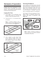
Figure 14. Biscuit location marks.
Layout Line
Registration
Mark
Figure 15. Layout lines and registration
marks.
Figure 16. Example of workpiece setup.
Model T31999 (Mfd. Since 02/20)-18-
Workpiece Preparation
Properly mark your workpieces to avoid
incorrect biscuit placement and wasted
material. The following example illustrates
a typical biscuit joining layout.
Laying Out Cuts
1. Place edges of (2) workpieces flush
against each other on a smooth, flat
surface. Verify board ends line up.
2. Place marks 2
1
⁄2"–3" from each end of
one board.
Note: If distance between marks is
greater than 6", place additional marks
at 4"–6" intervals (see Figure 14).
3
. Use a square to draw layout lines
across boards through marks, then
make registration marks on edge of
each board to ensure correct edge is
cut (see Figure 15).
Your workpiece must be properly secured
before making cuts. Cutting biscuit grooves
with a biscuit joiner places pressure on the
edge of the workpiece, which can cause
an improperly secured workpiece to shift
on the workbench, resulting in personal
injury or damage to the tool or workpiece.
Use clamps to secure workpiece on work-
bench. Edge of workpiece should hang
slightly over edge of workbench (see
Figure 16).
Securing Workpiece
Note: Clamps should be placed at
least 3" from any cut marks to prevent
interference with joiner.
Center
Line
Clamps
Workpiece
Page is loading ...
Page is loading ...
Page is loading ...
Page is loading ...
Page is loading ...
Page is loading ...
Page is loading ...
Page is loading ...
Page is loading ...
Page is loading ...
Page is loading ...
Page is loading ...
-
 1
1
-
 2
2
-
 3
3
-
 4
4
-
 5
5
-
 6
6
-
 7
7
-
 8
8
-
 9
9
-
 10
10
-
 11
11
-
 12
12
-
 13
13
-
 14
14
-
 15
15
-
 16
16
-
 17
17
-
 18
18
-
 19
19
-
 20
20
-
 21
21
-
 22
22
-
 23
23
-
 24
24
-
 25
25
-
 26
26
-
 27
27
-
 28
28
-
 29
29
-
 30
30
-
 31
31
-
 32
32


Grizzly T31999 Owner's manual
- Category
- Power universal cutters
- Type
- Owner's manual
Ask a question and I''ll find the answer in the document
Finding information in a document is now easier with AI
Related papers
-
Grizzly T10826 Owner's manual
-
-
-
Grizzly PRO T31634 Owner's manual
-
-
-
-
-
Grizzly Industrial G1037Z Owner's manual
-
 Grizzly Industrial G0555 Owner's manual

Other documents
-
 BLOTZ B10_WF_002 Assembly Instructions
-
909 BM018 User manual
-
Craftsman 315.175010 Owner's manual
-
-
King Canada KC-8306 User manual
-
General International 75-440 M1 User guide
-
-
Ryobi EBJ900K Owner's Operating Manual
-
DeWalt DW682K User manual
-
