Page is loading ...

SPRT®
SP-EU58 PRINTING UNIT
USER’S MANUAL
Version 1.01
Beijing Spirit Technology Development Co.,Ltd
www.sprt-printer.com

CONTENTS
1. Brief Instruction....................................................................................................... 1
2. Printing Unit............................................................................................................. 1
3. PCB board description........................................................................................... 3
4. Characteristic Specification...................................................................................8
4.1 Printing specification:.................................................................................... 8
4.2 Power supply..................................................................................................8
4.3 Interface.......................................................................................................... 8
4.4 Paper curing................................................................................................... 8
5. Operating instruction.............................................................................................. 9
5.1 Button and indicator instruction...................................................................9
5.2 Self-test........................................................................................................... 9
5.3 HEX Printing.................................................................................................10
5.4 The printer parameters setting.................................................................. 10
5.5 Enter into the program upgrading model................................................. 10
5.6 Paper loading...............................................................................................10
6. Printing commands...............................................................................................12
n = 1: Printer state..............................................................................................16
n = 2: Off line state.............................................................................................16
n = 3: error state.................................................................................................17
n = 4: paper sensor state.................................................................................. 17
n only LSB is available......................................................................................20
32 ≤ c1 ≤ c2 ≤ 126............................................................................................. 20
x × y ≤1536..........................................................................................................36
Two dimensional barcode control command.................................................45
1 ≤ k ≤ 6 Stand for magnification................................................................ 45
1 ≤ k ≤ 6 Stand for magnification................................................................ 45
7.Installation and use notes.....................................................................................52
Appendix A: 128 code......................................................................................... 54
A.1 128 code summary............................................................................................ 54
A.2 Character sets.................................................................................................... 54
Appendix A:Parameter setting................................................................................ 58

1
1. Brief Instruction
SP-EU58 is a kind of use of flexible, the function is all ready, the excellent
performance of new type thermal printing unit.
The clock mechanism、auto cutter and master control board position can be changed
as required by installation, To the greatest extent meet the needs of users flexible
structure change.
SP-EU58 print unit use 58mm thermal paper,65mm/s max print speed,meet the
user’s high speed printing require.
With Serial、parallel、USB etc interface for choosing, can easily communicate with
user control system.
Random character includes 24 * 24 bitmap GB18030 and BIG5 Chinese character, 9
* 24 and 12 * 24 a variety of international code page character lattice, user-friendly design.
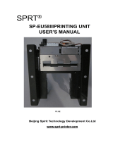
2. Printing Unit
1)SP-EU58 printing unit consists of printer head、auto cutter and PCB board,as following
figure:
Printer head and
auto cutter
PCB Board
20mm between cutter
and PCB Board
20mm

2
2) PCB board dimension(unit:mm):
It has four Φ3 mounting hole,the size refer above figure. Just need to fix the four
holes to install the PCB board.

3
3)Printer head dimension(unit:mm):
3. PCB board description
SP-EU58 can be sorted by different interface, include serial (RS-232C 、TTL 、
RS-485) 、parallel 、USB interface etc. PCB board also provides power, indicator light,
buzzer, movement and cutter, the paper on the key socket interface. Below is the explain
for the interfaces:
3.1 PCB board / keys/ interface instruction
Installing hole

4
3-1 SP-EU58 PCB board appearance figure
3.2 Pin assignment of serial port
The 5 pins sequence number of the single- row serial port is as Fig.1 shows:
5
4
3
2
1
3-2 SP-EU58 5 pins sequence number of the single- row serial port
Interface pins definition:
Pin
No.
Sign
al
Source
Description
1
DTR
Printer
Signal “MARK” indicates that the printer is
“BUSY” and unable to receive data ;“SPACE”
Indicates that the printer is “READY”
For receiving data .
2
TXD
Printer
Printer transmits data to host,and transmits control code
X-ON/X-OFF when using X-ON/X-OFF handshake protocol
3
RXD
Host
machine
Printer receives data from host
4
RTS
Printer
As DTR
5
GND
-
Signal Ground
The above is the default interface of serial port model.
Cutting socket
Printer head
Feed button
Serial port
USB port
Power socket
Indicators of status

5
3.3 customized serial interface appearance figure
3-3 SP-EU58 serial port
3.4 customized serial interface pins definition
SP-EU58 serial port can support RS-232C、TTL、RS-485 interface. Those interfaces
can be supported to user though two sockets,SJ1 and SJ2 sockets shown by figure 3-3.
SJ1 and SJ2 sockets’ definition of pin number are same as sequence, shown as 3-4.
3-4 SP-EU58 IDC-10 pin socket serial interface pin number definition
SJ1 and SJ2 are IDC-10 PIN socket, and same function, just the pin number
definition sequence is not same, the pin number definition as 3-2 and 3-3.
Notice:Do not use the two socket totally
Signal
Pin No.
Source
Description
TXD
3
Printer
Printer send data to computer
RXD
5
Host
machine
Printer receive data from computer
CTS
1,2,6,7
Printer
Printer with the host hardware flow
control signal
GND
9
-
ground
3-2 SP-EU58 series IDC-10 pin socket SJ1 serial interface pin number definition

6
Signal
Pin No.
Source
Description
TXD
2
Printer
Printer send data to computer
RXD
3
Host
machine
Printer receive data from computer
CTS
6,8
Printer
Printer with the host hardware flow
control signal
GND
5
-
ground
3-3 SP-EU58 series IDC-10 pin socket SJ1 serial interface pin number definition
Serial connection mode of baud rate and the structure of the data set, setting
software Settings are available, and factory has been set for the baud rate 9600 BPS, one
start bit, 8 data bits, 1 stop bit, no verify.
There are two handshaking protocol agreements to choose. One is hardware control,
other is X-ON/X-OFF agreement. Shown as below:
Signal
PTBDD
Serial interface signal
Hardware control
Data allow
Signal line of CTS is SPACE state
Data allow
Signal line of CTS is MARK state
XON/XOFF
control
Data allow
Send X-ON code 11H on TXD
Data allow
Send X-ON code 13H on TXD
3-4 SP-EU58 serial handshaking protocol agreement
3.5 The appearance of parallel interface
SP-EU58’s parallel interface is compatible with Centronics, its socket is connect with
26 pin cable, and the pin number definition as below:
3-5 SP-EU58 parallel socket pin number
3.6 Parallel interface pin number definition
SP-EU58’s parallel interface is compatible with Centronics ,its socket is connect with
26 pin cable, and the socket pin number definition as below:
Signal
Pin No.
Source
Description
/STB
1
Host
machine
Gate trigger

7
D1
3
Host
machine
The lowest of parallel data
D2
5
Host
machine
The second of parallel data
D3
7
Host
machine
The third of parallel data
D4
9
Host
machine
The fourth of parallel data
D5
11
Host
machine
The fifth of parallel data
D6
13
Host
machine
The sixth of parallel data
D7
15
Host
machine
The seventh of parallel data
D8
17
Host
machine
The highest of parallel data
/ACK
19
printer
Answer pulse, "low" level represent data has
been accepted and the printer is ready to
receive data
BUSY
21
printer
High level mean printer is busy and can not
receive data
PE
23
printer
High means out of paper, low means have
paper in it
SEL
25
-
resistance to the "high" level means
printer online
/ERR
4
-
resistance to the "high" level means no
problem with printer
NC
2、6、8
-
default dangling,can be Customized output 5V
GND
10、12、14、
16、18、20、
22、24
-
Grounding, logic 0 level
VCC
26
-
default dangling,can be Customized output 5V
3-5 SP-EU58 Parallel interface pin number definition
3.7 USB interface
Use the standard Mini-USB B interface, accord with USB2.0 standard.
3.8 Power supply interface
Power supply interface pin number definition show as 3-6

8
3-6 3PIN signal power supply interface socket pin number
Interface pin number definition as below:
Pin No.
Signal
Description
1
VIN
Input power anode(9-24V)
2
-
Dangling
3
GND
ground
4. Characteristic Specification
4.1 Printing specification:
Printing method:direct line thermal;
Printing paper :thermal paper 58*30mm
Printing paper width:57.5±0.5mm;
Printing width:48mm;
Resolution:8 dot/mm(203dpi);
Dots per line:384 dots;
Printing speed:Max 80mm/S(≤25% dots);
Paper thickness :0.06~0.08mm;
Printable content:GB18030 all Chinese and characters,all BIG5 traditional Chinese
character,ASCII character,self-defining character,one-dimensional bar
code,support different density map and downloading bitmap printing.
4.2 Power supply
DC (9~24)V±10%,2A
4.3 Interface
Serial interface(RS-232C, TTL, RS-485), parallel, USB (Mini USB)
4.4 Paper curing
(1) Paper type:Thermal paper
(2) Paper width:57.5±0.5mm
(3) Paper thickness:0.06~0.08 mm
(4) Paper supply method:Not drop-in easy loading
(5) Cutting method:Auto cutting ( Full/Partial cut)

9
5. Operating instruction
5.1 Button and indicator instruction
There are one button(Feed button)and one indicator,the indicator is red.The meanings of
indicator are as below:
Light constant on: print unit is on
Light flashing:printer has mistakes. Different types of mistake, different ways of
flashing
1. The mistake can be automatically recovered when the indicator continuous flashing.
Including the temperature mistake of printer head and opening of paper case cover.
Error
Description
The flashing way of [ERROR]
Temperature of
printer head
The temperature of printer head is
too high, it will recover
automatically when the
temperature is normal
Out of paper
errors
After installed the paper,it will
recover automatically when out of
paper.
2. The mistake can’t be automatically recovered when the indicator flashing some
times and constant on then cycle. The times of flashing means the type of mistake.
Error
Description
The flashing way of [ERROR]
ERROR
Memory
The printer can not work normally
after the memory need to be
read-write calibration
Over voltage
The voltage of power is too high
Owe voltage
The voltage of power is too low
The CPU
execution
The CPU execution to the wrong
address
Temperature
detection
circuit
Connection of temperature
detection circuit connection error
5.2 Self-test
After receiving the printer,user can check its current setting and status at anytime.
Self-test way is as below: Power off, then hold down the 【FEED】button and press
the power button at the same time. Then restart the printer.

10
5.3 HEX Printing
Hexadecimal print function: it will print out data received from the computer by
hexadecimal number and its corresponding characters, which is convenient for
adjusting program.
Enter the hex print method: during the power off, open “printing rubber roller” and
press “FEED” button, turn on the printer. After indicator flashing, release “FEED” and
close “printing rubber roller”. The printer enters into hex printing mode and prints the
indicating of entering printing mode.
Quit hex printing mode: turn off the power or press “FEED” button three times to exit
the hex printing mode and print the indicating of quitting hex printing mode.
5.4 The printer parameters setting
This function is to set up some simple parameters for the printer.
Enter into parameter setting method: In shutdown mode, open the 【printing rubber roller】
first, press the button of 【FEED】, then open the power supply, after the status indicators
light, release the button of【FEED】. Press the button of 【FEED】twice, then close the
【printing rubber roller】. The printer enters into parameter setting mode and prints out the
first set item and its current value. The details method can refer to Appendix.
Quit parameter setting method: Open the【printing rubber roller】first, press the button of
【FEED】, then close 【printing rubber roller】and release 【FEED】button. Save the set
parameter and quit parameter setting mode to enter normal working mode. If turn off the
printer directly through power button, the set parameters can’t be saved.
5.5 Enter into the program upgrading model
When printer is off, open the 【printing rubber roller】first, press the button of 【FEED】,
then open the power supply, after the status indicators and paper out lights flashing
alternant release the button of【FEED】. Press the button of 【FEED】five times, then close
the【printing rubber roller】. The printer enters into the program upgrade mode. Then the
status indicator light will flash as 1s speed.
5.6 Paper loading
Paper loading steps as below:
Pull the cutter, to open the paper feeding lever, put the thermal side of paper into the
rubber roller, and turn on paper knob to turn the paper out. As shown in figure 5-1:

11
5-1
Pull the cutter
Left the level
Put paper
Turn on paper
knob
Cutter exit for paper

12
6. Printing commands
Format specification
In this part, give instructions on how to use this section. Before programming, pls read this
section firstly.
Instruction of this chapter include the following parts:
1) Command name and description: this is the first part of the instructions of command.
ASCII is given the function of the form of instructions and the overview.
Form:this part show ASCII coding form, HEX form and Decimal form.
2) Format: there are three kinds of formats to describe the command – ASCII code, HEX
and Decimal.
If there are no special instructions for value range, it is the decimal number, for example 1
≤ n ≤ 4, this 1 is decimal number 1, not “1” in ASCII code.
3) Range:show the range of variety
4) Description:show the description for the command
5) Mark:Notice instructions are given. Because when different mode of command is used
with different commands together, they will affect each other. The details are given in this
section.
6) Reference: the related and similar commands with this command are given.
Example:
---> DLE EOT n Real time transmission status
---> [Format] ASCII DLE EOT n
Hex 10 04 n
Decimal 16 4 n
---> [Range] 1 ≤ n ≤ 4
---> [Description] Sending the printer state that designated by parameter n just in time
---> [Note] ·When printer receives the command, returns to the interrelated status
immediately
---> [Reference]
HT
[Name] Horizontal tab
[Format] ASCII HT
Hex 09
Decimal 9
[Description] Moves the print position to the next horizontal tab position.
[Note]
• This command is ignored unless the next horizontal tab position has been set.
• If the next position of horizontal tab exceeds the printing area, the current
position will be set as [printing width+1].
• Horizontal tab positions are set with ESCD.
•If the current position is at [printing width+1] when receives the command, the
printer will carry out the action in row buffer and move the printing position to the Zero
position of next line.
•The default value of tab position is every 8 standard ASCII characters (12*24) a tab.

13
•When the current row buffer is full, the printer will carry out the action below:
Under standard mode, printer prints the content of current row and sets the Printing
position at the zero position of next line
Under page mode, the printer begins a new line and set the printing position at the zero
position of next line.
[Reference] ESC D
LF
[Name] Printing and feeding line
[Format] ASCII LF
Hex 0A
Decimal 10
[Description] Printing the data in the print buffer and feeds one line
[Note] This command sets the print position to the beginning of the line.
[Reference] ESC 2, ESC 3
FF
[Name] Printing and feeding paper
[Format] ASCII FF
Hex 0C
Decimal 12
[Description] Printing all of the content in print buffer and returning to the standard mode,
under the standard mode, if the printer establishes in the black mark paper
mode, then printing the data in the buffer to feed paper to the black mark
section, if haven’t black mark, then feed the paper 30cm behind stop, the
pre-print black mark specification is showed in the appendix B. The pre-print
black mark instruction. If not at the black mark examing status and then only
print the contents of buffer, don’t feed paper.
[Note] Clearing the content in print buffer after printing.
·The printing area setup by ESC W returns to the default
·The printer won’t cut paper.
This command sets the current position at the beginning of the line
[Reference] ESC FF, ESC L, ESC S
CR
[Name] Printing and entering
[Format] ASCII CR
Hex 0D
Decimal 13
[Description] The same as LF when the command is permitted, if not, it will be
ignored.
[NOTE] Setting the printing position at the beginning of the line.
·The command is ignored under the serial interface mode.

14
·The printer allocation decides If the command is enabled under parallel
mode.
[Reference] LF
DLE EOT n
[Name] Real time status transmission
[Format] ASCII DLE EOT n
Hex 10 04 n
Decimal 16 4 n
[Range] 1 ≤ n ≤ 4
[Description] Sending the printer state that designated by parameter n just in time:
n=1:Sending state of the printer
n=2:Sending off line state
n=3:Sending error state
n=4:Sending state of paper sensor
[Note] -When printer receives the command, returns to the interrelated status
immediately
Avoiding to put this command in the command sequence of more than 2
characters.
This command will be also valid even though the printer is set to forbid by
the
Command of ESC=(selecting peripheral ).
When sending printer current state, each state is indicated by 1 byte
Transmission state value of the printer can not confirm whether the master
computer received
Printer will carry out the command immediately once received
This command is just available to the serial printer. The printer will carry out
the
command immediately under any state
LF
[Name] Printing and feeding line
[Format] ASCII LF
Hex 0A
Decimal 10
[Description] Printing the datas in the print buffer and feeds one line
[Note] This command sets the print position to the beginning of the line.
[Reference] ESC 2, ESC 3

15
FF
[Name] Printing and feeding paper
[Format] ASCII FF
Hex 0C
Decimal 12
[Description] Printing all of the content in print buffer and returning to the standard mode,
under the standard mode, if the printer establishes in the black mark paper
mode, then printing the data in the buffer to feed paper to the black mark
section, if haven’t black mark, then feed the paper 30cm behind stop, the
pre-print black mark specification is showed in the appendix C.the pre-print
black mark instruction.If not at the black mark examing status and then only
print the contents of buffer, don’t feed paper.
[Note] Clearing the content in print buffer after printing.
·The printing area setup by ESC W returns to the default
·The printer won’t cut paper.
This command sets the current position at the beginning of the line
[Reference] ESC FF, ESC L, ESC S
CR
[Name] Printing and entering
[Format] ASCII CR
Hex 0D
Decimal 13
[Description] The same as LF when the command is permitted, if not ,
it will be ignored.
[NOTE] Setting the printing position at the beginning of the line.
·The command is ignored under the serial interface mode.
·The printer allocation decides If the command is enabled under parallel
mode.
[Reference] LF
DLE EOT n
[Name] Real time status transmission
[Format] ASCII DLE EOT n
Hex 10 04 n
Decimal 16 4 n
[Range] 1 ≤ n ≤ 4
[Description] Sending the printer state that designated by parameter n just in time:
n=1:Sending state of the printer
n=2:Sending off line state
n=3:Sending error state
n=4:Sending state of paper sensor

16
[Note] -When printer receives the command, returns to the interrelated status
immediately
Avoiding to put this command in the command sequence of more than 2
characters.
This command will be also valid even though the printer is set to forbid by
the
Command of ESC=(selecting peripheral ).
When sending printer current state, each state is indicated by 1 byte
Transmission state value of the printer can not confirm whether the master
computer received
Printer will carry out the command immediately once received
This command is just available to the serial printer. The printer will carry out
the
command immediately under any state
n = 1: Printer state
Bit
0/1
HEX
Decimal
Function
0
0
00
0
Fix as 0
1
1
02
2
Fix as 1
2
0
00
0
The cash box open/close signal is low(the third of cash
box plug leads foot)
1
04
4
The cash box open/close signal is high(the third of
cash box plug leads foot)
3
0
00
0
online
1
08
8
offline
4
1
10
16
Fix as 1
5,6
undefined
7
0
00
00
Fix as 0
n = 2: Off line state
Bit
0/1
HEX
Decimal
Function
0
0
00
0
Fix as 0
1
1
02
2
Fix as 1
2
0
00
0
close the top cover
1
04
4
open the top cover
3
0
00
0
Not holding down the feed button
1
08
8
holding down the feed button
4
1
10
16
Fix as 1
5
0
00
0
Printer is not out of paper
1
20
32
Printer is out of paper
6
0
00
0
No error state
1
40
64
error state
7
0
00
0
Fix as 0

17
n = 3: error state
Bit
0/1
HEX
Decima
l
Function
0
0
00
0
Fix as 0
1
1
02
2
Fix as 1
2
-
-
-
undefined
3
0
00
0
noun cutter error
1
08
8
cutter error
4
1
10
16
1 fix as 1
5
0
00
0
noun unrecoverable error
1
20
32
have unrecoverable error
6
0
00
0
noun auto recoverable error
1
40
64
have auto recoverable error
7
0
00
0
fix as 0
n = 4: paper sensor state
Bit
1/0
HEX
Decimal
Function
0
0
00
0
Fix as 0
1
1
02
2
Fix as 1
2,3
0
00
0
The sensor of paper is going out: have enough paper
1
0C
12
The sensor of paper is going out :the paper is going out
4
1
10
16
Fix as 1
5,6
0
00
0
lack of paper sensor: have paper
1
60
96
lack of paper sensor: noun paper
7
0
00
0
Fix as 0
[Reference] DLE ENQ, GS a, GS r
ESC SP n
[Name] Setting the right space of characters
[Format] ASCII ESC SP n
Hex 1B 20 n
Decimal 27 32 n
[Range] 0 ≤ n≤255
[Description] Setting the right space of character for [n*units of vertial or lateral
shifting]
-When the character enlarges, the space enlarges the same times.
-The command doesn’t affect the setup of Chinese characters.
-The value which is set by the command under page and standard mode is
mutual independence.
-Units of vertial or lateral shifting area pointed by GSP. Changing units of
vertial
or lateral shifting does not change the current right space.
-Using lateral shifting units under standard mode.

18
-According to the direction of printing area and the beginning position to
select
vertical or lateral shifting units under page mode.
The selection modes areas below:
①Using lateral shifting when the beginning position is the top left or lower right
corner of the printing area which is set by ESC T;
②Using vertical shifting when the beginning position is the lower left or top right
corner of the printing area which is set by ESC T;
The maximum right space is 255/203 inches.If setting beyond this value, it will
automatically change into the maximum distance.
[Default] n = 0
[Reference] GS P
ESC ! n
[Name] selecting print mode
[Format] ASCII ESC ! n
Hex 1B 21 n
Decimal 27 33 n
[Range] 0 ≤ n ≤ 255
[Description]
Setting character print mode according to value of n
Bit
1/0
HEX
Decima
l
Function
0
0
00
0
Standard ASCII style A (12×24)
1
01
1
Compressing ASCII style B(9×17)
1,2
Undefined
3
0
00
0
Cancel bold font
1
08
8
Select bold font
4
0
00
0
Cancel double height mode
1
10
16
Select double height mode
5
0
00
0
Cancel double width mode
1
20
32
Select double width mode
6
undefined
7
0
00
0
Cancel underline mode
1
80
128
Select underline mode
[Note] -When selected double-height or double-width mode, double size characters
are printed.
-Any character can be added underline except the space set by HTand the
characters clockwise 90 degrees.
-Underline is not related to characters but confirmed by ESC-.
-When some characters in a line are double or more height, all the
/