Page is loading ...

User Instructions
V-SHOCK® & V-SHOCK® EDGE Personal Fall Limiter (PFL)
Fall Protection
Order No.: 10226385(Print Only), 10236349/01 (Master)
Print Spec: 10000005389 (R)
CR: 800000056035
MSAsafety.com
US

© MSA 2022. All rights reserved
WARNING!
These instructions must be provided to users before use of the product and retained for ready reference by the user. Read this
manual carefully before using or maintaining the device. The device will perform as designed only if it is used and maintained in
accordance with the manufacturer's instructions. Otherwise, it could fail to perform as designed, and persons who rely on this
device could sustain serious injury or death.
The warranties made by MSA with respect to the product are voided if the product is not installed and used in accordance with
the instructions in this manual. Please protect yourself and your employees by following the instructions.
Please read and observe the WARNINGS and CAUTIONS inside. For additional information relative to use or repair, call
1-800-MSA-2222 during regular working hours.
MSA is a registered trademark of MSA Technology, LLC in the US, Europe and other Countries. For all other trademarks visit
https://us.msasafety.com/Trademarks.
MSA - The Safety Company
1000 Cranberry Woods Drive
Cranberry Township, PA 16066
USA
Phone: 1-800-MSA-2222
Fax: 1-800-967-0398
For your local MSA contacts, please go to our website www.MSAsafety.com

US V-SHOCK & V-SHOCK EDGE PFL 4
Contents
1 Labels and Icons 5
1.1 Product Details and Warnings 6
2 Safety Regulations 7
3 Product Specification 9
4 Harness Attachment 9
4.1 Attach V-SHOCK Single Leg PFL to Harness 10
4.2 Attach V-SHOCK Twin Leg PFLs to Harness Using V-SHOCK TwinLink Connector 10
4.3 Attach V-SHOCK EDGE PFLs to Harness Using V-SHOCK EDGE Pin Connector 11
5 Installation and Use 12
5.1 Intended Use 12
5.2 General Installation and Use 12
5.3 Leading Edge Installation and Use 13
5.4 Mobile Elevated Work Platform / Aerial Lift / Bucket Truck Installation and Use 14
6 Fall Clearances 15
6.1 V-SHOCK Fall Clearance Charts 15
6.2 V-SHOCK Tieback Fall Clearance Charts 17
6.3 V-SHOCK EDGE Fall Clearance Charts 18
6.4 V-SHOCK EDGE Tieback Fall Clearance Charts 20
7 Pre-Use Checks and Periodic Examinations 22
8 Cleaning and Storage 24
9 Warranty 24

5 V-SHOCK & V-SHOCK EDGE PFL US
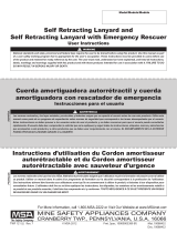
1 Labels and Icons
1 Labels and Icons
V-SHOCK PFLs - Non-Leading Edge V-SHOCK EDGE PFLs - Leading Edge
Gray Housing
(Non-Leading
Edge)
Non-Leading
Edge Icon
Scannable
RFID
Serial
Number
Labels located beneath flap indicated by
"refer to instruction manual" icon.
Green Housing
(Leading Edge)
Leading Edge
Icon
Scannable
RFID
Serial
Number
Labels located beneath flap indicated by
"refer to instruction manual" icon.
1 Capacity including user, clothing, and
tools.
6 Tested for use over corrugated steel
edge.111 ANSI Class.2
2 Tie off above D-ring permitted. 7 WARNING! Read and understand
instruction manual before use.
12 Load indicator NOT
deployed.
3 Tie off below D-ring permitted. 8 Refer to instruction manual. 13 Load indicator
deployed,
DONOTUSE.
4 Tested for use over an edge.19 Tie off below D-ring NOT permitted. 14 Fall clearance chart.3
5 Tested for use over steel edge.110 Do NOT user over an edge. 15 WARNING!
1 - See Section 5.3 Leading Edge Installation and Use for details and limitations.
2 - See Section 5 Installation and Use for details.
3 - See Section 6 Fall Clearances for details.

1 Labels and Icons
US V-SHOCK & V-SHOCK EDGE PFL 6
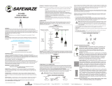
1.1 Product Details and Warnings
V-SHOCK Labels
V-SHOCK EDGE Labels
Table 1 ANSI / OSHA / CSA Label Data
1Serial number 5Model number
2Lifeline construction 6Standard
3Length 7Notified body number
4Date of manufacture (mm/yy) 8Product warning

7 V-SHOCK & V-SHOCK EDGE PFL US
2 Safety Regulations
2 Safety Regulations
V-SHOCK V-SHOCK EDGE
WARNING!
User Requirements
lUsers of Personal Fall Limiters (PFLs) shall be medically fit and suitably trained.
lPFLs shall not be used by pregnant women, minors or those under the influence of alcohol or drugs.
lFor single user only, within the weight range 130–310 lbs (60–141 kg) for ANSI, 100–400 lbs (45–181 kg) for OSHA
overhead applications, or 100–310 lbs (45–141 kg) for CSA, including user, clothing, and tools.
Anchor Requirements/Swing Fall/Fall Clearance
lThe anchorage must be capable of supporting the required load. See Section 3 Product Specification for details on
anchorage strength.
lEnsure that the available fall clearance is equal to or greater than the fall clearance shown in Section 6 Fall
Clearances.
lRemove any surface contamination such as, but not limited to, concrete, stucco, roofing material, etc. that could
accelerate cutting or abrading of attached components.
lFor use in accordance with acceptable locations as shown in Section 6 Fall Clearances. The user shall consider any
risks posed by swing falls.
lSwing falls can increase fall distance. In overhead applications, work directly under the anchorage. In horizontal
(leading edge) applications, minimize the horizontal offset. Increasing the horizontal offset will increase the amount
of swing fall. Always remove obstructions in or adjacent to the fall path. Keep work area free from debris,
obstructions, trip hazards, spills, or other hazards which could impair the safe operation of the fall protection system.
For horizontal (leading edge) applications DO NOT use the device unless a qualified person has inspected the
workplace and determined that the identified swing fall hazards have been eliminated or exposures to them
prevented.
Product Use
lPFLs are only to be used for their intended purpose and within their limitations. DO NOT intentionally misuse this
product. DO NOT use fall protection equipment for purposes other than those for which it was designed. DO NOT
use fall protection equipment for towing, hoisting, or material handling.

2 Safety Regulations
US V-SHOCK & V-SHOCK EDGE PFL 8
lPFLs shall not be altered or added to. No unauthorized repairs, modifications, alterations and/or additions are
permitted.
lRESCUE AND EVACUATION: the user must have a rescue plan and the means at hand to implement it. The plan
must take into account the equipment and specific training necessary to affect prompt rescue under all foreseeable
conditions. If the rescue must be performed in a confined space, the provisions of OSHA regulation 1910.146 and
ANSIZ117.1 must be taken into account. It is recommended to provide means for user evacuation without
assistance of others. This will usually reduce the time to get to a safe place and reduce or prevent the risk to
rescuers.
lDO NOT rely on feel or sound to verify proper connector engagement. Ensure the connector is closed before use.
lAdditional lanyard connectors shall not be added, as this would serve to lengthen the lifeline and increase free fall.
lUnsuitable for use on unstable surfaces, fine grain materials or particulate surfaces such as sand or coal, as
insufficient speed may prevent lock-on in the event of a fall (possible engulfment hazard).
lDO NOT use where line may be exposed to abrasive edges. For leading edge guidance, see Section 5.3 Leading
Edge Installation and Use.
lPFLs shall not come into contact with hot surfaces (such as hot pipes), become entangled with moving machinery, or
come into contact with electrical hazards (such as high voltage power lines).
lPFLs shall be protected from fire, acids, caustic solutions, or temperatures outside the range -40°F to 130°F (-40°C
to 54°C).
lDO NOT leave the PFL installed in environments which could cause damage or deterioration to the product. Refer to
the care details in Section 8 Cleaning and Storage and inspection details in Section 7 Pre-Use Checks and Periodic
Examinations.
lInstructions shall be retained and provided to all users of PFLs in the language of the destination country, even when
resold.
lDO NOT exceed the maximum fall arrest forces as specified by governing standards or subsystem components.
lDual-connections shall only be made for the purposes of 100% tie-off transitions, if a dual connection is made for any
other purpose, anchorages of different elevations must be utilized.
lUse of combinations of components or subsystems, or both, may affect or interfere with the safe function of the
components or subsystems. Use only compatible components or subsystems, never add additional length to the
system.
Leading Edge-Specific Product Use (V-SHOCK EDGE Products)
• Use in edge situations should only be as a last resort.
• Avoid working where the lifeline will continuously or repeatedly abrade against sharp, jagged, or abrasive edges.
• The V-SHOCK EDGE PFL anchorage point shall be at the user’s foot level or above.
• Do not work on the far side of an opening opposite the anchorage point or around corners.
lOnly use V-SHOCK EDGE PFLs for leading edge applications. Do NOT use V-SHOCK PFLs for leading edge
applications.
lLeading edge configurations shall only be used after all other hierarchy of controls, including restraint systems and
overhead anchorages, have been exhausted.
lLeading edge configurations shall only be used in accordance with local regulations.
lLeading edge configurations shall be used in accordance with the instructions, warnings and limitations in these User
Instructions.
lIn leading edge applications with 0 ft (0 m) setback, ensure that setup does not allow snaphook to contact leading
edge in the event of a fall.

9 V-SHOCK & V-SHOCK EDGE PFL US
3 Product Specification
Inspection/Removing Product From Service
lPFLs that have arrested a fall or are unable to pass an inspection shall be tagged “UNUSABLE” and disposed of in
accordance with local regulations.
lDue to the nature of some fall arrest events, it is possible for the load indicator to not deploy. In the event that a PFL is
subjected to fall arrest forces and the load indicator does not deploy, the PFL still must be removed from service and
marked as “UNUSABLE” until it has been destroyed.
lIf the load indicator is deployed, immediately remove the PFL from service and mark it as “UNUSABLE” until it has
been destroyed.
Failure to follow these warnings can result in serious personal injury or death.
3 Product Specification
System Requirements
Component ANSI/OSHA CSA
Anchorage Connector Standard ANSI Z359.18/OSHA1926.502,
1910.140
CSA Z259.14/CSA Z259.15
Harness Standard ANSI Z359.11/OSHA1926.502,
1910.140
CSA Z259.15
Connectors Standard ANSI Z359.12/OSHA1926.502,
1910.140
CSA Z259.12
Retractable Type Fall Arresters ANSI Z359.14/OSHA1926.502,
1910.140
CSA Z259.2.2-17
Structure Strength 3600 lbs (16 kN) certified 5000 lbs (22.2
kN) non-certified
5000 lbs (22.5 kN)
NOTE: The product may comply with standards shown. See product label for specific compliance information. Those
designated with a certification mark are listed with the corresponding agency as compliant to the applicable standard.
PFL Materials
Component Material
Case Nylon
Drum Aluminum
Pawl, Swivel Assembly,
Main Spring
Steel
Lifeline 1.00” (25.4mm) wide / 0.14” (3.6mm) thick HMPE / para-aramid blend OR1.00” (25.4mm)
wide / 0.11” (2.8mm) thick Polyester
Connectors Steel OR Aluminum
Energy Absorber Nylon
Energy Absorber Pouch Polyester
4 Harness Attachment
WARNING!
DO NOT rely on feel or sound to verify proper connector engagement. Ensure the connector is closed before use.
Failure to follow this warning can result in serious personal injury or death.

4 Harness Attachment
US V-SHOCK & V-SHOCK EDGE PFL 10
4.1 Attach V-SHOCK Single Leg PFL to Harness
A V-SHOCK PFL may be connected to an approved full body harness by feeding the carabiner through the back D-ring of
the harness. In these applications, the snaphook is connected to a suitable anchorage with the appropriate connecting
hardware.
4.2 Attach V-SHOCK Twin Leg PFLs to Harness Using V-SHOCK TwinLink Connector
A V-SHOCK TwinLink connector can be used to connect two V-SHOCK PFLs side-by-side on a full body harnessjust
below the rear D-ring or through the PFL tunnel. The V-SHOCK TwinLink connector shall only be used to connect a
maximum of two V-SHOCK PFLs to the harness.*
* The V-SHOCK TwinLink (minus the clip) may be used to attach directly to a full body harness D-ring.
1. If harness has PFL tunnel—use
PFL tunnel as connection point.
If harness does not have PFL
tunnel—Lift D-ring on harness
and pull straps through dorsal
pad until V-SHOCK PFL can feed
between webbing straps and
dorsal pad.
2. Unclip plastic divider on V-
SHOCK TwinLink connector.
Rotate, lift, and twist gate on
carabiner. Push gate inward to
open carabiner.
3. Feed carabiner through swivel
eyelet on first V-SHOCK PFL.
4. Feed carabiner through PFL
tunnel or behind both straps on
harness.
5. Feed swivel eyelet of second V-
SHOCK PFL onto carabiner and
allow carabiner gate to snap shut.
Rotate plastic divider and clip it
into position to maintain
separation of PFLs.
6. If harness has PFL tunnel—
Installation complete.
If harness does not have PFL
tunnel—Pull harness straps back
through dorsal pad to eliminate
slack in webbing.

11 V-SHOCK & V-SHOCK EDGE PFL US
4 Harness Attachment
4.3 Attach V-SHOCK EDGE PFLs to Harness Using V-SHOCK EDGE Pin Connector
The V-SHOCK EDGE PFL pin connector allows connection to a full body harness just below the rear D-ring or through the
PFL tunnel.
1. If harness has PFL tunnel—use PFL tunnel as
connection point.
If harness does not have PFL tunnel—Lift D-ring on
harness and pull straps through dorsal pad until
V-SHOCK EDGE pin connector can feed between
webbing straps and dorsal pad.
2. Press the button on right side of the pin and press
the button on the top of the right side of the bracket.
Pull the pin to the right to open the pin connector.
3. With the button on the pin depressed, feed the pin
through PFL tunnel or behind both straps on harness to
the left side of the bracket.
a. Release the button on the pin and pull on the end
of the pin slightly to ensure it has locked into
place.
4. If harness has PFL tunnel— Installation complete.
If harness does not have PFL tunnel— Pull harness
straps back through dorsal pad to eliminate slack in
webbing.

5 Installation and Use
US V-SHOCK & V-SHOCK EDGE PFL 12
5 Installation and Use
5.1 Intended Use
PFLs are intended to be used as a connecting element between a full body harness and anchor point. See Section 3
Product Specification. A full body harness is the only acceptable body holding device to be used with a PFL. If supplied as
part of a complete system, components shall not be substituted.
For ANSIusers:Maximum Arrest force is 1800 lb (8 kN), Average Arrest Force is 1350 lb (6 kN), Maximum Arrest Distance
is 3.5 ft (1.1 m).
WARNING!
lPFLs are only to be used for their intended purpose and within their limitations. DO NOT intentionally misuse this
product. DO NOT use fall protection equipment for purposes other than those for which it was designed. DO NOT
use fall protection equipment for towing, hoisting, or material handling.
lPFLs shall not be altered or added to. No unauthorized repairs, modifications, alterations and/or additions are
permitted.
lRESCUE AND EVACUATION: the user must have a rescue plan and the means at hand to implement it. The plan
must take into account the equipment and specific training necessary to affect prompt rescue under all foreseeable
conditions. If the rescue must be performed in a confined space, the provisions of OSHA regulation 1910.146 and
ANSIZ117.1 must be taken into account. It is recommended to provide means for user evacuation without
assistance of others. This will usually reduce the time to get to a safe place and reduce or prevent the risk to
rescuers.
lDO NOT rely on feel or sound to verify proper snaphook or carabiner engagement. Ensure that gate and keeper are
closed before use.
lAdditional lanyard connectors shall not be added, as this would serve to lengthen the lifeline and increase free fall.
lUnsuitable for use on unstable surfaces, fine grain materials or particulate surfaces such as sand or coal, as
insufficient speed may prevent lock-on in the event of a fall (possible engulfment hazard).
lDO NOT use where line may be exposed to abrasive edges. For leading edge guidance, see Section 5.3 Leading
Edge Installation and Use.
lPFLs shall not come into contact with hot surfaces (such as hot pipes), become entangled with moving machinery, or
come into contact with electrical hazards (such as high voltage power lines).
lPFLs shall be protected from fire, acids, caustic solutions, or temperatures outside the range -40°F to 130°F (-40°C
to 54°C).
Failure to follow these warnings can result in serious personal injury or death.
5.2 General Installation and Use
Connectors: Ensure PFL connectors are compatible with the attachments to which they are connected (to prevent roll-
out), and are fully closed and locked before use. See Section 3 Product Specification.
Anchors: Ensure the PFL is attached to a compatible anchor –flexible anchors, such as anchor lines, horizontal lifelines,
rail or cantilever structures can affect the ability of the PFL to lock-on in the case of a fall. For further clarification on
compatibility specifications, refer to the user instructions of the flexible anchor product. Should compatibility information not
be included in the flexible anchor user instructions, contact the flexible anchor manufacturer for clarification.
Retraction: In use, the PFL lifelines will extract and retract without hesitation. Do not allow the lifeline to pass through legs
or under arms, or wrap around structure. If the lifeline does not retract in use, fully extract the lifeline and slowly allow it to
retract. If the lifeline continues to hesitate in retraction, contact MSA.

13 V-SHOCK & V-SHOCK EDGE PFL US
5 Installation and Use
Twin Leg Connection: The PFL twin-leg configuration is intended to give users 100% tie-off when moving around the
work site. One of the legs must be attached to an appropriate anchorage connector while the user moves to the new
location. At the new location, attach the second leg to an appropriate anchorage connector before disconnecting the
original leg. Repeat this process until the final destination has been reached. Do NOT work with both legs connected to an
anchorage connector.
WARNING!
Dual-connections shall only be made for the purposes of 100% tie-off transitions, if a dual connection is made for any other
purpose, anchorages of different elevations must be utilized.
Failure to follow this warning can result in serious personal injury or death.
Tieback Connection: The PFL Tieback configuration is intended to give users the ability to anchor directly to structural
members that have been suitably identified by a qualified person. To use: wrap the leg of the PFL around the identified
structural member and connect the FP5K snaphook to the leg to create a closed loop. Be sure the snaphook gate is
completely closed, locked, and captures the leg of the PFL. Inspect anchorage to assure the tie-back loop on the leg of the
PFL cannot be accidentally disengaged from the anchorage during use.
Storage: When not in use, store with the lifeline fully retracted as prolonged periods of full extraction may weaken the
retraction spring. Guide the lifeline back to the unit for full retraction. Do NOT release lifeline from a distance as it will retract
at high speed, potentially damaging internal parts. The connector may also strike objects in its path, causing damage to
those objects and to the connector. See Section 8 Cleaning and Storage for full cleaning and storage instructions.
5.3 Leading Edge Installation and Use
If a fall over an edge is possible, special rescue measures shall be defined and trained for. Consideration shall be given to
accessing a suspended user without further loading or moving the lifeline over an edge.
WARNING!
lOnly use V-SHOCK EDGE PFLs for leading edge applications. Do NOT use V-SHOCK PFLs for leading edge
applications.
lLeading Edge configurations shall only be used after all other hierarchy of controls, including restraint systems and
overhead anchorages, have been exhausted.
lLeading Edge configurations shall only be used in accordance with local regulations.
lLeading Edge configurations shall be used in accordance with the instructions, warnings and limitations in these
User Instructions.
Failure to follow these warnings can result in serious personal injury or death.
Harness Connection: V-SHOCK EDGE PFL configurations shall be attached only using the PFL tunnel or below the D-
ring as shown in Section 4.3 Attach V-SHOCK EDGE PFLs to Harness Using V-SHOCK EDGE Pin Connector. Do not
attach additional connectors between the bracket and harness, attempt to bypass the connecting bracket, or connect
directly to the PFL mechanism.
Horizontal Offset: When using V-SHOCK EDGE PFL configurations in a horizontal (leading edge) application, the
horizontal distance apart shall be ≤ 10 ft (3 m). Large horizontal spans shall be avoided, as they can increase forces
applied to the structure and introduce swing falls.
Edge Types: The V-SHOCK EDGE PFL configurations have been tested for horizontal (leading edge) use over a steel
edge without burrs using the methods in ANSI Z359.14-2021 (Class 2) and CSA Z259.2.2-2017 (Class SRL-LE).
Therefore, the V-SHOCK EDGE PFL may be used where a fall may occur over similar edges.

5 Installation and Use
US V-SHOCK & V-SHOCK EDGE PFL 14
Additionally, while the ANSI Z359.14- 2021 (Class 2) or CSA Z259.2.2-2017 (Class SRL-LE)
standards do not address edges other than steel, the V-SHOCK EDGE PFL has been tested
using the methods in ANSI Z359.14-2021 with the following edges:
A cold formed corrugated steel test edge. Edges used for testing were at thicknesses ranging
from 22 gage (0.0295" / 0.7493 mm) to 16 gage (0.0598" / 1.5189 mm). Therefore, V-SHOCK
EDGE PFL configurations may be used where a fall may occur over similar edges.
Edge Evaluation: Prior to use, leading edges must be evaluated by a qualified person. Use in these edge situations
should only be as a last resort. Avoid working where the lifeline will continuously or repeatedly abrade against sharp,
jagged, or abrasive edges. If the risk assessment indicates that an edge could damage the lifeline, then eliminate such
contact or protect the edges using a pad or other means before starting work.
Anchorage Considerations: Horizontal (leading edge) use or anchoring at the feet of the user should be limited wherever
possible to avoid the potential for swing fall and the possibility of the user striking a structure, potentially causing serious
injury. To reduce the risk of a swing fall, anchor directly above the user.
Lateral movements to both sides of the center axis shall be limited to a maximum 10 ft (3 m) as shown. The V-SHOCK
EDGE PFL anchorage point shall be at the user’s foot level or above. Climbing above the anchorage point is not permitted.
Measures shall be taken to prevent use over unintended edges. Do not work on the far side of an opening opposite the
anchorage point or around corners.
WARNING!
• Anchor locations shall adhere to charts in Section 6 Fall Clearances, including a redirection angle ≥ 90° and set back
≥ 0 ft (0 m)*.
* In leading edge applications with 0 ft (0 m) setback, ensure that setup does not allow snaphook to contact leading
edge in the event of a fall.
• Avoid working where the lifeline will continuously or repeatedly abrade against sharp, jagged, or abrasive edges. Use
in these situations should only be as a last resort.
• The V-SHOCK EDGE PFL anchorage point shall be at the user’s foot level or above.
• Do not work on the far side of an opening opposite the anchorage point or around corners.
Failure to follow this warning can result in serious personal injury or death.
For CSA users: Deployment is equal to [D141 = 0.9] times [4 ft (1.23 m)] for a maximum worker 310 lbs (141 kg) or
deployment based on the results of the dynamic performance testing specified in Clause 7.2, whichever is greater.
5.4 Mobile Elevated Work Platform / Aerial Lift / Bucket Truck Installation and Use
V-SHOCK EDGE 6 ft (1.8 m) PFL standard configurations (tieback configurations NOT permitted) are approved for use in
mobile elevated work platforms, aerial lifts, and bucket trucks provided the hazards described below are considered. In
addition, the user is advised to perform an evaluation by a competent person for other fall-related hazards unique to this
application.
Hazards
lAvoid exposing the lifeline to working over an exposed sharp edge. Sharp edges may cut the line. However, the
rounded bars of a guard rail are acceptable for the line to pass over.
lA fall out of the platform can result in a swing-fall hazard, with the potential for the worker to strike the boom of the
aerial lift device or other objects in the path of the fall.

15 V-SHOCK & V-SHOCK EDGE PFL US
6 Fall Clearances
Requirements for Use
lThe V-SHOCK EDGE 6 ft (1.8 m) PFL must be attached to a certified anchor point within the platform of the lift.
lUser weight capacity, including clothing and tools, is 310 lbs (141 kg).
lUser must ensure a minimum clearance below the platform of 8.5 ft (2.6 m). Clearance is calculated for a rigid
anchor, if a non-rigid anchor is being used then a qualified person should evaluate for additional clearance
considerations.
6 Fall Clearances
6.1 V-SHOCK Fall Clearance Charts
6 ft V-SHOCK PFL: 6 ft / 1.8 m Length
10 ft V-SHOCK PFL: 10 ft / 3 m Length
V-SHOCK Single PFL V-SHOCK Twin PFL
Product: V-SHOCKPFL
Use: Non-leading edge applications
Capacity: ≤ 310 lbs (141 kg)
NOTE: OSHA limits free fall to 2 ft (0.6
m) or less.

6 Fall Clearances
US V-SHOCK & V-SHOCK EDGE PFL 16
Product: V-SHOCKPFL
Use: Non-leading edge applications
Capacity: ≤ 400 lbs (181 kg)
NOTE: OSHA limits free fall to 2 ft (0.6
m) or less.

17 V-SHOCK & V-SHOCK EDGE PFL US
6 Fall Clearances
6.2 V-SHOCK Tieback Fall Clearance Charts
6 ft V-SHOCK Tieback PFL: 6 ft / 1.8 m Lifeline + 3 ft / 0.9 m (Total Length: 9 ft / 2.7 m) *
10 ft V-SHOCK Tieback PFL:10 ft / 3 m Lifeline + 3 ft / 0.9 m (Total Length: 13 ft / 4 m) *
* Tieback section = 3 ft / 0.9 m
V-SHOCK Tieback Single PFL V-SHOCK Tieback Twin PFL
Product: V-SHOCK Tieback PFL
Use: Non-leading edge applications
Capacity: ≤ 310 lbs (141 kg)
NOTE: OSHA limits free fall to 2 ft (0.6
m) or less.
If the V-SHOCK Tieback PFLis
anchored around a structural member
that has been suitably identified by a
qualified person, the fall clearance may
be reduced by an amount equal to the
circumference of the object, up to 3ft
(0.9m).
Product: V-SHOCK Tieback PFL
Use: Non-leading edge applications
Capacity: ≤ 400 lbs (181 kg)
NOTE: OSHA limits free fall to 2 ft (0.6
m) or less.
If the V-SHOCK Tieback PFL is
anchored around a structural member
that has been suitably identified by a
qualified person, the fall clearance may
be reduced by an amount equal to the
circumference of the object, up to 3ft
(0.9m).

6 Fall Clearances
US V-SHOCK & V-SHOCK EDGE PFL 18
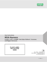
6.3 V-SHOCK EDGE Fall Clearance Charts
6 ft V-SHOCK EDGE PFL: 6 ft / 1.8 m Length
10 ft V-SHOCK EDGE PFL: 10 ft / 3 m Length
V-SHOCK EDGE Single PFL V-SHOCK EDGE Twin PFL
Product: V-SHOCK EDGEPFL
Use: Leading edge applications
Capacity: ≤ 310 lbs (141 kg)
(A) Clearance values shown are based on 0 ft (0 m)
anchorage setback from the leading edge.
Anchorage connector may be used at setback
distance of 0 ft (0 m)* from the leading edge or as far
back as required. For every 1 ft (0.3 m) the
anchorage location is set back from the leading edge,
the user can subtract 0.5 ft (0.15 m) from the
clearance provided in the chart based on the user's
offset distance.
NOTE: Clearance chart anchorage location for
illustrative purposes only.
ILLUSTRATION NOT TO SCALE
WARNING!
* In leading edge applications with 0 ft (0 m) setback, ensure that setup does not allow snaphook to contact leading edge
in the event of a fall.
Failure to follow this warning can result in serious personal injury or death.

19 V-SHOCK & V-SHOCK EDGE PFL US
6 Fall Clearances
Product: V-SHOCK EDGE PFL
Use: Non-leading edge applications
Capacity: ≤ 310 lbs (141 kg)
NOTE: See Section 5 Installation and
Use for clearance in Mobile Elevated
Work Platform / Aerial Lift / Bucket
Truck applications.
Product: V-SHOCK EDGE PFL
Use: Non-leading edge applications
Capacity: ≤ 400 lbs (181 kg)

6 Fall Clearances
US V-SHOCK & V-SHOCK EDGE PFL 20
6.4 V-SHOCK EDGE Tieback Fall Clearance Charts
6 ft V-SHOCK EGDE Tieback PFL: 6 ft / 1.8 m Lifeline + 2 ft / 0.6 m (Total Length: 8 ft / 2.4 m) *
10 ft V-SHOCK EGDE Tieback PFL:10 ft / 3 m Lifeline + 2 ft / 0.6 m (Total Length: 12 ft / 3.6 m) *
* Tieback section = 3 ft / 0.9 m
V-SHOCK EDGE Tieback Single PFL V-SHOCK EDGE Tieback Twin PFL
Product: V-SHOCK EDGETieback PFL
Use: Leading edge applications
Capacity: ≤ 310 lbs (141 kg)
(A) Clearance values shown are based on 2 ft (0.6 m)
anchorage setback from the leading edge. Anchorage
connector may be used at setback distance of 2 ft (0.6
m) from the leading edge or as far back as required.
For every 1 ft (0.3 m) the anchorage location is set
back from the initial 2 ft (0.6 m) setback, the user can
subtract 0.5 ft (0.15 m) from the clearance provided in
the chart based on the user's offset distance.
If the V-SHOCK EDGE Tieback PFL is anchored
around a structural member that has been suitably
identified by a qualified person, the initial setback of 2
ft (0.6 m) may be reduced by an amount equal to the
circumference of the object, up to 2 ft (0.6 m).
NOTE: Clearance chart anchorage location for
illustrative purposes only.
ILLUSTRATION NOT TO SCALE
WARNING!
* In leading edge applications with 0 ft (0 m) setback, ensure that setup does not allow snaphook to contact leading edge
in the event of a fall.
Failure to follow this warning can result in serious personal injury or death.

21 V-SHOCK & V-SHOCK EDGE PFL US
6 Fall Clearances
Product: V-SHOCK EDGE Tieback PFL
Use: Non-leading edge applications
Capacity: ≤ 310 lbs (141 kg)
NOTE: If the V-SHOCK EDGE Tieback
PFLis anchored around a structural member
that has been suitably identified by a
qualified person, the fall clearance may be
reduced by an amount equal to the
circumference of the object up to 2 ft (0.6m).
Product: V-SHOCK EDGE Tieback PFL
Use: Non-leading edge applications
Capacity: ≤ 400 lbs (181 kg)
NOTE: If the V-SHOCK EDGE Tieback
PFLis anchored around a structural
member that has been suitably identified by
a qualified person, the fall clearance may be
reduced by an amount equal to the
circumference of the object up to 2 ft (0.6m).
/


