Page is loading ...

1. Remove the plastic dischage spout from the
discharge housing.
INSTALLATION INSTRUCTIONS
DISCHARGE DIVERTER KIT
FOR SQUEEZE BELT CONVEYORS
Publication No. 1035332
1035332-1
ASSEMBLY
2. Referring to Figs. 1, 2 & 9, fasten the two mount
angles (Items 2) to the four mounting slots in the
discharge housing that were used to mount the
discharge spout. Use four 3/8” x 1-1/4” long bolts
with nylon locknuts. Use two 3/8” flat washers per
bolt (one under head and one under nut.)
3. Mount a UHMW panel (Item 3) to each of the
mounting angles (Item 2), using two 3/8” x 1-1/4”
long bolts with nylon locknuts. Use two 3/8” flat
washers per bolt (one under head and one under
nut). The end of the UHMW panel with the nine
holes is used.
0401171 0401174
FIG. 1 FIG. 2
5. Slide a 3/4” flat washer over each of the pivot rods
of the pivot rod weldment (Item 4).
6. Slide the tubes of the pivot plate weldment (Item 5)
over the rods of the pivot rod weldment (Item 4).
Install another 3/4” flat washer over each pivot rod
and secure in place with a 3/16” x 1-1/2” long cotter
pin in each pivot rod.
7. Mount the top cable anchor angle (Item 1) across
the top end of the discharge housing. Use two
3/8” x 2” long bolts and nylon lock nuts. Place four
3/8” flat washers at each bolt between the housing
and the angle (Item 1) to space the angle away
from the housing. This provides room for the
discharge cover to fit between the housing and the
top cable anchor angle.
4. Mount a pivot rod weldment (Item 4) to the other
end of each UHMW panel (Item 3) using two 3/8”
x 1-1/4” long bolts with nylon locknuts. Use two
3/8” flat washers per bolt (one under head and one
under bolt).

Page 2
1035332-2
INSTALLATION INSTRUCTIONS
DISCHARGE DIVERTER KIT
FOR SQUEEZE BELT CONVEYORS
ASSEMBLY - CONT.
0401173 0401172
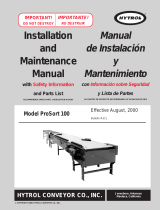
9. Hook a pulley clevis assembly (from Step 8) into
the 1-1/4” diameter holes in each end of the top
cable anchor angle (Item 1).
10.Install a 1/4” x 1-1/4” long bolt into each pulley clevis
assembly and secure with a 1/4” side depress lock
nut. These bolts serve to keep the cable from
coming off the cable pulley (Item 7) during
operation.
11.Referring to Figs. 4 and 5, install the cable handle
latch brackets (Items 10) to the top of the lowest
conveyor return roll support. The brackets
(Items 10) will mount with the existing 1/4” bolts
used to mount the upper wind guard panels. There
will be a bracket (Item 10) on each side of the
conveyor.
8. Refer to Fig. 3 and assemble the two cable pulleys
(Items 7) between the pulley clevis plates
(Items 6). There should be a pulley bushing
(Item 8) inserted into the bore of each pulley
(Item 7). Use a 1/2” x 2” long bolt and lock nut to
secure each pulley.
12.Fasten a cable pull handle (Item 11) to a section
of 3/16” chain (Item 12) that is 21 links in length.
Use a 5/16” x 1” long bolt with flat washer and
nylon locknut. Repeat for second handle and chain.
13.If the conveyor truss side bars or angles do not
have the mounting holes for the cable guides, it
will be necessary to field drill them. Measure up
approximately 14-1/2” from the lower bend of the
truss side and drill two 13/32” diameter holes
15/16” apart on centers. (See cross section view
of Fig. 5.)
FIG. 3
FIG. 4

INSTALLATION INSTRUCTIONS
DISCHARGE DIVERTER KIT
FOR SQUEEZE BELT CONVEYORS
ASSEMBLY - CONT.
Page 3
14. Enough u-bolts are provided for installation at three
truss supports. On 35’ & 45’ models, there is only
one truss support. Thread two 3/8” non-lock nuts
onto each 3/8” u-bolt until the nuts are threaded on
as far as they will go. Install the u-bolts through
the holes drilled in Step 13 and install two more
3/8” non-lock nuts top secure in place.
15.Thread the two 3/16” cables (Items 9) though the
u-bolts at each truss support. NOTE: Enough cable
length is provided for the 90’ models. On shorter
models, the cable will be cut to an appropriate
length later.
16.Wrap the upper end of each cable around the
1-1/16” diameter tube of the pivot plate weldment
(Item 5), Figs. 1 & 2. The cable will go above the
3/4” flat washer and below the cross plate of the
pivot weldment. Clamp the cable end with a 3/16”
cable clamp. The u-bolt portion of the clamp should
be against the loose (short) end of the cable.
1035332-3
17.Referring to Fig. 5, at a point approximately 18”
past the lower truss support, make a loop in each
cable and install a 3/16” cable clamp. This prevents
too much slack cable from developing past the
truss support when the cables are not being pulled
to move the deflector panels.
18.Loop the other end of each cable (Items 9) through
the last link in each chain (Items 12) referred to in
Step 12. Before looping the other end of the cable
(Item 9) through the last link in each chain (Item
12) referred to in Step 12, find the center link on
the section of chain (Item 12) and position that link
in the center slot of the cable latch bracket (Item
10). See Fig. 7. This will allow enough travel in
both cables during operation. It is recommended
to check the operational travel both ways before
cutting the cable. See Fig. 10. Cut any excess
cable off and install a 3/16” cable clamp. U-bolt
portion of clamp should be against the loose (short)
end of the cables (Items 9).
19.The cable tensions are adjusted by pulling with
the pull handles (Items 11) and hooking the chain
links (Items 12) into the slotted notches of the cable
latch brackets (Items 10). See Fig. 8.
0401175
FIG. 5

INSTALLATION INSTRUCTIONS
DISCHARGE DIVERTER KIT
FOR SQUEEZE BELT CONVEYORS
ASSEMBLY - CONT.
Page 4
0401262 1035332-4
FIG. 6

1035332-5
INSTALLATION INSTRUCTIONS
DISCHARGE DIVERTER KIT
FOR SQUEEZE BELT CONVEYORS
ASSEMBLY - CONT.
Page 5
REF. PART
NO. NO. DESCRIPTION QTY.
1 1034895 Top Cable Anchor Angle 1
2 1034882 Mount Angle 2
3 1034881 UHMW Side Panel 2
4 1034887 Pivot Rod Weldment 2
5 1034888 Pivot Plate Weldment 1
6 1007890 Pulley Clevis Plate 4
7 1008195 Cable Pulley 2
8 1012347 Pulley Bushing 2
9 1011984 Cable 3/16” x 100’ 2
10 1034891 Cable Latch Bracket 2
11 1034892 Cable Pull Handle 2
12 1026368 Link Chain 3/16” x 21 links 2
13 4841 U-Bolt 3/8” x 5/8” Spread 1 at each truss
side support
14 D1149 3/8” Non-lock Nut 4 per u-bolt

1035332-6
INSTALLATION INSTRUCTIONS
DISCHARGE DIVERTER KIT
FOR SQUEEZE BELT CONVEYORS
ASSEMBLY - CONT.
Page 6
0401311 0401312 0401313 0401314
FIG. 7
FIG. 8
FIG. 9
FIG. 10
/