
tsss2isi
Battery Operated Self-Propelled
Mobile Elevating Work Platform
The COMPACTS and CONVENTIONALS
Models 3015, 3219, 3220, 4620,
4626, 4830, 4832, 6826 and 6832
tsss2isi
yiesxq2wexev
Revised 99-04-01 Printed in CANADA

The Safety Alert Symbol identifies important safety messages on machines,
safety signs, in manuals, or elsewhere. When you see this symbol, be
alert to the possibility of personal injury or death. Follow the instructions
in the safety message.
gyi2yp2rs2wexev
This manual applies to the ANSI/SIA, CSA and CE versions of the SJIII
work platform models listed on Page 7. Equipment identified with ANSI/
SIA meets the ANSI/SIA-A92.6 standards. Equipment identified with CSA
meets CAN3-B354.2&.3-M82 standards. Equipment identified with CE
meets the requirements for the European countries, i.e. Machinery Directive
89/392/EEC and EMC Directive 89/336/EEC and the corresponding EN
standards.
DO NOT OPERATE THIS EQUIPMENT WITHOUT PROPER AU-
THORIZATION AND TRAINING. DEATH OR SERIOUS INJURY
COULD RESULT FROM IMPROPER USE OF THIS EQUIPMENT!
isgi2yvsg2exh2eex
SKYJACK, Inc. warrants each new SJIII Series work platform to be free of
defective parts and workmanship for first 12 months. Any defective part
will be replaced or repaired by your local SKYJACK dealer at no charge
for parts or labor. Refer to the Warranty Statement for extensions or
exclusions.
NOTE
SKYJACK, Inc. is continuously improving and expanding product features
on its equipment: therefore, specifications and dimensions are subject
to change without notice.
This Safety alert Symbol means
Attention! Become Alert!
Your Safety Is Involved
OPERATOR SAFETY REMINDER
The National Safety Council reminds us that most accidents are caused
by the failure of some individuals to follow simple and fundamental safety
rules and precautions. Common sense dictates the use of appropriate
safety devices and protective clothing to protect your eyes, hands, feet
and body.
You, as a careful operator, are the best insurance against an accident.
Therefore, proper usage of this work platform is mandatory. The following
pages of this manual should be read and understood completely before
operating the work platform. Any modifications from the original design
are strictly forbidden without written permission from SKYJACK, Inc.

SUBJECT - SECTION, PARAGRAPH PAGE NO.
SECTION 1 - INTRODUCTION
PURPOSE OF EQUIPMENT ................................................................................................... 1
USE OF EQUIPMENT ............................................................................................................. 1
WARNINGS ......................................................................................................................... 1
DESCRIPTION ........................................................................................................................ 1
PLATFORM ......................................................................................................................... 1
OPERATORS CONTROL BOX ............................................................................................... 1
MANUAL STORAGE BOX ...................................................................................................... 1
LIFTING MECHANISM ............................................................................................................ 2
BASE ...................................................................................................................................... 2
LOWERING WARNING SYSTEM (CE only) ........................................................................... 2
SCISSOR GUARDS (CE only) ................................................................................................ 2
SERIAL NUMBER NAMEPLATE ............................................................................................. 2
OPTIONAL ACCESSORIES .................................................................................................... 3
SAFETY PANEL LABELS ........................................................................................................ 4
WARNINGS ........................................................................................................................... 5
SPECIFICATIONS AND FEATURES ........................................................................................ 6
STANDARD/OPTIONAL EQUIPMENT ..................................................................................... 7
WORK PLATFORM MAJOR COMPONENT IDENTIFICATION ............................................... 8
SECTION 2 - OPERATION CONTROLS IDENTIFICATION
AND PROCEDURES
IDENTIFICATION
OPERATING CONTROLS IDENTIFICATION ........................................................................... 9
ELECTRICAL PANEL .............................................................................................................. 9
EMERGENCY BATTERY DISCONNECT SWITCH .................................................................10
BASE CONTROL BOX (CE) .................................................................................................. 11
SAFETY BAR & POTHOLE PROTECTION DEVICE ............................................................... 12
PLATFORM CONTROLS ....................................................................................................... 14
POWERED EXTENSION PLATFORM CONTROL BOX ......................................................... 16
FOLD-DOWN GUARDRAIL SYSTEM .................................................................................... 17
PROCEDURES
OPERATING PROCEDURES .................................................................................................18
SETUP PROCEDURES .......................................................................................................... 18
PRESTART PROCEDURES ................................................................................................... 21
EMERGENCY LOWERING SYSTEM PROCEDURES ............................................................24
SHUT DOWN PROCEDURES ................................................................................................ 25
TOWING AND FREE-WHEELING PROCEDURES ................................................................. 26
BATTERY SERVICE PROCEDURES ......................................................................................28
BATTERY CHARGING PROCEDURES (STANDARD MACHINE ............................................29
BATTERY CHARGING PROCEDURES (EE-RATED MACHINES) ..........................................29
BATTERY CHARGING PROCEDURES .................................................................................. 30
BYCAN CHARGER ................................................................................................................ 30
MOTOR APPLIANCE CHARGER ........................................................................................... 31
efvi2yp2gyxix
i

SUBJECT - SECTION, PARAGRAPH PAGE NO.
SECTION 3 - MAINTENANCE
OPERATORS RESPONSIBILITY FOR MAINTENANCE .........................................................33
MAINTENANCE AND INSPECTION SCHEDULE .................................................................... 33
GENERAL MAINTENANCE HINTS .........................................................................................33
LIST OF TABLES
TABLE 1-1. SPECIFICATIONS AND FEATURES .................................................................... 6
TABLE 3-1. MAINTENANCE AND INSPECTION SCHEDULE ................................................ 34
TABLE 3-2. MAXIMUM PLATFORM CAPACITIES ........................................................... 35-36
TABLE 3-3. GENERAL SPECIFICATIONS ....................................................................... 37-39
efvi2yp2gyxix
ii

xyi
iii

PURPOSE OF EQUIPMENT
The SKYJACK SJIII Series Work Platform is designed to transport and
raise personnel, tools and materials to overhead work areas.
USE OF EQUIPMENT
The work platform (Figure 1-2. Page 9) is a highly maneuverable, mobile
work station. Lifting and driving MUST be on a flat, level, compacted
surface.
WARNINGS
The operator MUST read and completely understand the safety panel
labels (Figure 1-1. Page 5) and ALL other warnings in this manual and
on the work platform (Ref. Page 6). Compare the labels on the work
platform with the labels found throughout Section 2 of this manual. If
any labels are damaged or missing, replace them immediately.
DESCRIPTION
The work platform consists of three major assemblies, the platform,
lifting mechanism and the base. An operators control box is mounted
on the platform railing. Auxiliary and emergency controls are located
at the base.
PLATFORM
The platform is constructed of a tubular support frame, a skid-resistant
deck surface, and 40 to 43-1/2 (1016-1105mm) high railings
(depending on model) with 6" toe boards and mid-rails. The platform
can be entered from the rear through an entry chain or optional spring-
returned gate with latch. The platform is also equipped with an extension
platform.
OPERATORS CONTROL BOX
A removable control box, mounted at the right front of the platform,
contains controls for work platform motion and emergency stopping.
MANUAL STORAGE BOX
This weather resistant box is mounted at the front of
the platform directly below the safety panel. It contains
the Operating Manual, Operating/Maintenance and
Parts Manual and other important documentation. The
Operating Manual for this make and model work
platform MUST remain with the work platform and
should be stored in this box.
Page 1
igsyx2I INTRODUCTION

LIFTING MECHANISM
The lifting mechanism is constructed from steel tubing making up a
scissor-type assembly. The scissor-type assembly is raised and lowered
by single-acting hydraulic lift cylinder(s). A pump, driven by a motor,
provides hydraulic power to the lift cylinder(s). A safety bar located at
the front of the lifting mechanism prevents (when properly positioned)
the scissor-type assembly from being lowered while maintenance or
repairs are being performed within the lifting mechanism. (See page
13)
BASE
The base is a rigid one-piece weldment which supports two swing-out
trays. On Models 3015, 3219, 3220, 4620, 4626, 4830 and 4832, a
mechanically actuated angle, located under the outside of the trays,
rotates when lifting. This mechanism provides pothole protection for
elevated driving (see page 14). One tray contains the hydraulic and
electrical components. The other tray contains the battery charger
and four (4) 6 volt batteries . On Models 3015 and 3219; the front axle
has two hydraulic motor-driven wheels , steerable by a hydraulic cylinder.
The rear axle is fixed and has two spring-applied hydraulically-released
parking brakes. On Models 3220, 4620, 4626, 4830, 4832, 6826 and
6832; the front axle has two non-driven wheels, steerable by a hydraulic
cylinder. The rear axle has two hydraulic motor driven wheels and two
spring-applied, hydraulically-released parking brakes.
LOWERING WARNING SYSTEM (CE only)
Models 3015, 3219, 3220, 4620, 4626, 4830 and 4832 are equipped
with a lowering warning system as standard equipment (See page 25).
SCISSOR GUARDS (CE only)
Models 6826 and 6832 are equipped with rigid scissor guards mounted
on the base as standard equipment.
SERIAL NUMBER NAMEPLATE
The serial number nameplate, located at the rear of the machine, lists
the model number, serial number, machine weight, drive height, capacity
and maximum no. of persons, maximum speed, maximum manual force,
maximum incline, platform height, voltage, system pressure, lift
pressure, ground pressure (tire contact pressure), and date
manufactured. Use this information for proper operation and
maintenance and when ordering service parts.
Page 2
igsyx2I INTRODUCTION

OPTIONAL ACCESSORIES
The SKYJACK SJIII Series Work Platform is designed to accept a variety
of optional accessories. These are listed in (Page 8 Specifications and
Features. Operating instructions for these options (if required) are
located in Section 2 of this manual.
igsyx2I INTRODUCTION
Page 3

igsyx2I SAFETY PANEL LABELS
Page 4
Figure 1-1. Safety Panel Labels
(Located at the front center of the platform on the railing)
22hexqi
22222exsxq
OTHER HAZARDS
TIP-OVER HAZARDS
ELECTROCUTION HAZARD
hy2xy2hsi2xie2hyEyppD2ryvi
yix222iviey22repD2exh2vyehsxq22hyguF
DO NOT RAISE PLATFORM ON SLOPE OR DRIVE
ONTO SLOPE WHEN ELEVATED.
DO NOT RAISE PLATFORM ON
UNEVEN OR SOFT SURFACES
DO NOT DRIVE ONTO UNEVEN
OR SOFT SURFACES WHEN
ELEVATED.
DO NOT RAISE PLATFORM IN
WINDY OR GUSTY
CONDITIONS.
FAILURE TO AVOID THESE HAZARDS WILL
RESULT IN DEATH OR SERIOUS INJURY!
VOLTAGE MINIMUM SAFE
OVER 750KV TO
PHASE TO
AVOID CONTACT
OVER 500KV TO
OVER 350KV TO
OVER 200KV TO
OVER 50KV TO
OVER 300V TO
(0 TO 300V)
10 3.05
FEET (METERS)
45 13.72
35 10.67
15 4.60
20 6.10
25 7.62
1. DO NOT OVERLOAD.
2. DO NOT USE WITHOUT RAILINGS, LOCK PINS, AND ENTRY GATE/CHAIN/BAR IN PLACE.
3. DO NOT USE WITHOUT LOCK PINS INSTALLED ON HINGED RAILINGS.
4. DO NOT USE IF WORK PLATFORM IS NOT WORKING PROPERLY OR IF ANY PART IS DAMAGED OR WORN.
5. DO NOT STAND OR SIT ON GUARDRAILS.
6. DO NOT ATTACH ROPES OR CHAINS TO GUARDRAILS OR USE AS A CRANE.
7. DO NOT USE UNDER INFLUENCE OF ALCOHOL OR DRUGS.
8. DO NOT OVERRIDE SAFETY DEVICES.
9. DO NOT LEAVE MACHINE UNATTENDED WITH KEY IN SWITCH.
10. DO NOT RAISE PLATFORM WHILE MACHINE IS ON A TRUCK, FORK LIFT, OR OTHER DEVICE OR
VEHICLE.
11. DO NOT USE LADDER, SCAFFOLDING, OR OTHER DEVICES TO INCREASE THE WORKING HEIGHT OF
PLATFORM.
12. DO NOT USE WITH IMPROPERLY INFLATED/DAMAGED TIRES OR WHEELS.
13. DO NOT USE WHEELS OR TIRES THAT ARE NOT ORIGINAL MANUFACTURERS EQUIPMENT.
rs2wegrsxi2s2xy2sxveihF2wesxesx2epi
gvieexgi2pyw2ivigsgev2yi2vsxi2exh
eeeF
y2w2evvy2py2vepyw2eD2yguD2y2eqF
rs2vepyw2hyi2xy2yshi2yigsyx2pyw
gyxeg2sr2y2ysws2y2ex2ivigsgevv
greqih2gyxhgyF
pesvi2y2eysh2rii2reeh22gyvh
iv2sx2hier2y2isy2sxt3

DO NOT exert excessive side forces on platform while elevated.
DO NOT overload, the lift relief valve does not protect against over-
loading when the platform is elevated.
DO NOT alter or disable limit switches or other safety devices.
DO NOT raise your platform in windy or gusty conditions.
DO NOT exceed the rated capacity of your scissorlift and make sure
the load is evenly distributed on the platform.
DO NOT operate on surfaces not capable of holding weight of the
work platform including the rated load, e.g. covers, drains, and
trenches.
BE AWARE of overhead obstacles, and poorly lit areas in case of over-
head obstacles.
DO NOT elevate the work platform if it is not on firm level surfaces.
Avoid pot holes, loading docks, debris, drop offs and surfaces that
may affect the stability of your work platform.
DO NOT climb or descend a grade steeper than 20% (SJIII Compacts),
or 25% (SJIII Conventionals). Elevated driving must only be done on
firm level surfaces. (Ref. Table 1-1)
ENSURE that there is no person(s) in the path of travel.
An Operator Should Not Use Any Work Platform That:
Has ladders, scaffolding or other devices mounted on it to increase
its size or work height.
Does not have a clean, uncluttered work area.
Does not appear to be working properly.
Has been damaged or appears to have worn or missing parts.
Has alterations or modifications not approved by the manufacturer.
Has safety devices which have been altered or disabled.
exsxq
tyfsi2reeh
igsyx2I WARNINGS
Page 5
exsxq
yu2vepyw2gyxhssyx

GRAD-
ABILITY
20% +
20% +
25%
25%
25%
25%
25%
25%
25%
Page 6
MODEL WEIGHT WIDTH LENGTH
HEIGHT
Working Platform Lowered Drive**
PLATFORM
Size Capacity* TIRES
SPEED (Max.)
QHIS
QPIW
2360 lbs.
(1070kg)
2600 lbs.
(1179kg)
30.50
(.77m)
32.50
(.83m)
66.50
(1.69m)
66.50
(1.69m)
21.0
(6.4m)
25.0
(7.6m)
15.0
(4.6m)
19.0
(5.8m)
78.0
(1.98m)
79.0
(2.01m)
FULL
FULL
28 x 64
(.71x1.63m)
28 x 64
(.71x1.63m)
500 lbs.
(227kg)
500 lbs.
(227kg)
@
@
Drive
2 mph
(3.2km/h)
2 mph
(3.2km/h)
Raise
21
sec.
30
sec.
* Overall capacity with manual extension platform shown - occupants and materials not to exceed rated load. NOTE: Capacities may
be reduced when equipped with powered extension platform. Refer to Table 3-2 on Page 37 for additional information.
@ 12 x 4.00 x 8 Non-Marking Solid Rubber @@ 16 x 4.00 x 8 Non-Marking Solid Rubber @@@ 23 x 10.5 x 12 Foam Filled
**Drive heights apply to all ANSI machines. For drive heights to CSA and CE machine standards contact SkyJack Inc.
Table 1-1. Specifications and Features
QPPH
RTPH
3860 lbs.
(1751kg)
3593 lbs.
(1630kg)
32.00
(.81m)
46.00
(1.17m)
89.00
(2.26m)
89.00
(2.26m)
26.0
(7.9m)
26.0
(7.9m)
20.0
(6.1m)
20.0
(6.1m)
79.9
(2.03m)
80.2
(2.03m)
FULL
FULL
28 x 81
(.71x2.05m)
42 x 81
(1.07x2.05m)
800 lbs.
(363kg)
1100 lbs.
(499kg)
@@
@@
2 mph
(3.2km/h)
2 mph
(3.2km/h)
35
sec.
35
sec.
RTPT 4198 lbs.
(1904kg)
46.00
(1.17m)
89.00
(2.26m)
32.0
(9.8m)
26.0
(7.9m)
89.0
(2.26m) FULL 42 x 81
(1.07x2.05m)
850 lbs.
(386kg) @@ 2 mph
(3.2km/h)
44
sec.
TVPT
TVQP
5020 lbs.
(2277kg)
5480 lbs.
(2486kg)
68.00
(1.73m)
68.00
(1.73m)
99.25
(2.52m)
99.25
(2.52m)
32.0
(9.8m)
38.0
(11.6m)
26.0
(7.9m)
32.0
(9.8m)
95.0
(2.41m)
99.0
(2.51m)
FULL
FULL
60 x 81
(1.53x2.05m)
60 x 81
(1.53x2.05m)
1200 lbs.
(545kg)
1000 lbs.
(454kg)
@@@
@@@
2 mph
(3.2km/h)
2 mph
(3.2km/h)
47
sec.
51
sec.
RVQH 5630 lbs.
(2554kg)
48.00
(1.22m)
89.00
(2.26m)
36.0
(11.0m)
30.0
(9.1m)
93.5
(2.37m) FULL 42 x 81
(1.07x2.05m)
700 lbs.
(317kg) @@ 2 mph
(3.2km/h)
45
sec.
RVQP 5630 lbs.
(2554kg)
48.00
(1.22m)
89.00
(2.26m)
38.0
(11.6m)
32.0
(9.8m)
93.5
(2.37m) FULL 42 x 81
(1.07x2.05m)
600 lbs.
(272kg) @@ 2 mph
(3.2km/h)
45
sec.

Spring-Loaded Half-Height Gate (ANSI only)
Spring-Loaded Full-Height Gate
Movement Alarm
Flashing Amber Light
800W AC Generator
EE-Rating Package
Air (Power) Package
(UL Approved, Class 1, Div 1Group D)
(All Models Except 3015 and 3219)
Propane/Gasoline or Diesel Engine Package
(All Models Except 3015, 3219 and 3220)
Shop Air Line to Platform
Hydraulically Powered Extension Platform
Puncture-Proof Solid Rubber Black Tires
Lowering Warning System (ANSI only)
(Models 3015, 3219, 3220, 4620, 4626 and 4830)
Scissor Guards (ANSI only) (Models 6826 and 6832)
Light duty Pipe Rack
Operator Horn
Descent Alarm
Proportional Joystick Forward/Reverse and Lift Control
Swing-out Side Trays
Two Spring-Applied Hydraulically-Released Parking Brakes
Puncture-Proof, Solid Rubber Non-Marking Tires
(All Models Except 6826 and 6832)
Manual Lowering System With Lift Cylinder Holding Valve(s)
Tilt Alarm With Lift/Drive Cutout
3 Foot Extension Platform
Lanyard Attachment Rings
Front Wheel Drive With Tight Turning Radius
(Models 3015 and 3219)
Lowering Warning System (CE only)
(Models 3015, 3219, 3220, 4620, 4626 and 4830, 4832)
Scissor Guards (CE only) (Models 6826 and 6832)
Spring-Loaded Half-Height Gate (CE only)
AC Outlet on Platform
STANDARD FEATURES
(ANSI & CE)
OPTIONAL EQUIPMENT
(ANSI & CE)
Page 7

Figure 1-2. SJIIISeries Work Platform
(Model 3219 shown)
Page 8
igsyx2I
WORK PLATFORM MAJOR COMPONENT IDENTIFICATION
OPERATORS
CONTROL
CONSOLE
EXTENSION
PLATFORM
LIFTING
MECHANISM
BASE
POTHOLE
PROTECTION
DEVICE
MAIN
PLATFORM
HYDRAULIC/
ELECTRIC
TRAY
BATTERY
TRAY

OPERATING CONTROLS IDENTIFICATION
The following descriptions are for identification, explanation and locating
purposes only. A qualified operator MUST read and completely
understand these descriptions before operating this work platform.
Procedures for operating this work platform are detailed in the
OPERATING PROCEDURES section on Pages 19 thru 33. Both
standard and optional controls are identified in this section. Therefore,
some controls may be included that are not furnished on your work
platform.
ELECTRICAL PANEL
Figure 2-1. Electrical Panel
(Model 3219 ANSI/SIA and CSA shown)
1. Buzzer Alarm
2. Hourmeter
3. 15 AMP Circuit Breakers Resets
4. Up/Down Toggle Switch (ANSI/SIA and CSA)
ELECTRICAL PANEL
This control station is located in the Hydraulic/Electric Tray. It contains
the following controls:
1. Buzzer Alarm
This audible pulse alarm sounds when platform is being electrically
lowered. As an option this alarm will also sound when other control
functions are selected.
2. Hourmeter
Activated when the pump/motor runs, this meter records work platform
operating time.
Page 9
2
1
4
3
igsyx2P
OPERATION CONTROLS IDENTIFICATION AND PROCEDURES

3. 15 AMP Circuit Breaker Resets
In the event of a power overload or positive circuit grounding, circuit
breaker will pop out. Make the necessary corrections, then depress
the push-button to reset.
4. Up/Down Toggle Switch (ANSI/SIA and CSA)
Selecting and holding this toggle type switch to UP position will raise
platform to desired height. Release switch to stop. Selecting and holding
switch to DOWN position will lower platform to desired height. Release
switch to stop.
EMERGENCY BATTERY DISCONNECT SWITCH
Figure 2-2. Emergency Battery Disconnect Switch
(Model 3219 shown)
1. Emergency Battery Disconnect Switch
1. Emergency Battery Disconnect Switch
Located on the rear of the base, this switch, when in OFF position,
disconnects power to all control and power circuits. Switch MUST be
in ON position to operate any control circuit.
1
Page 10
igsyx2P OPERATION CONTROLS IDENTIFICATION

BASE CONTROL BOX (CE)
Figure 2-3. Base Control Box (CE)
(Model 3220 shown)
1. Platform Up/Down Toggle Switch
2. Emergency Stop Button
BASE CONTROL BOX (CE)
This metal control station is mounted on the rear of the base. It contains
the following controls:
1. Platform Up/Down Toggle Switch
To raise the platform, select BASE position with the Base/Off/Platform
Select Key Switch (Figure 2-5. on Page 15), then push this toggle-type
switch to the ñ (up) position. Release switch to stop. To lower the
platform, select BASE position with the Base/Off/Platform Select Key
Switch (Figure 2-5. on Page 15), then push this toggle-type switch to
the ò (down) position. Release switch to stop.
2. Emergency Stop Button
When struck, this red push-button switch disconnects power to both
the base and the platform control boxes. In the event of an emergency
or at work platform shut down, push the button in. To restore power,
simply pull the button out.
1
2
Page 11
igsyx2P OPERATION CONTROLS IDENTIFICATION

SAFETY BAR & POTHOLE PROTECTION DEVICE
Figure 2-4. Safety Bar and Pothole Protection Device
(Model 3219 shown)
1. Safety Bar
2. Pothole Protection Device
1. SAFETY BAR
Designed to support the scissors assembly (when properly positioned),
the safety bar MUST be used when inspecting or when performing
maintenance or repairs within the scissor assembly with the platform
raised. To use the safety bar, follow the procedure on the safety bar
label on the base.
DANGER
CRUSHING HAZARD
DO NOT reach through the scissor assembly when the platform is
raised without the safety bar properly positioned. Failure to avoid
this hazard will result in death or serious injury!
2
1
Page 12
igsyx2P OPERATION CONTROLS IDENTIFICATION

2. POTHOLE PROTECTION DEVICE
This device consists of a mechanically actuated angle, located under
the outside of the trays, which automatically rotates for a reduced ground
clearance when elevated. If this device is not fully lowered, the drive
function will be disabled.
DO NOT drive elevated in areas where electrical cords or debris is in
the path of travel.
DO NOT drive elevated into holes, depressions, trenches, shafts or soft
or uneven surfaces.
2222222exsxq
Page 13
igsyx2P OPERATION CONTROLS IDENTIFICATION
22222222exsxq
grsxq2reeh
Personnel on ground MUST stay clear of pot hole protection bar.

igsyx2P OPERATION CONTROLS IDENTIFICATION
Page 14
PLATFORM CONTROLS
Operators Control Box
Figure 2-5. Operators Control Box
1. Off/On Key Switch (ANSI/SIA and CSA) (shown)
2. Base/Off/Platform Select Key Switch (CE)
3. High/Normal Torque Select Toggle Switch
(Models 3220, 4620, 4626, 4830, 4832, 6826 and 6832 only)
4. Lift/Off/Drive Select Toggle Switch
5. Proportional Controller
6. Emergency Stop Button
7. Operator Horn Push-Button
OPERATORS CONTROL BOX
This metal control station is mounted at the right front of the platform.
It contains the following controls:
1. Off/On Key Switch (ANSI/SIA and CSA)
Key to OFF position disconnects power to the control circuit in the
operators control box. Key to ON position energizes the control circuit.
2. Base/Off/Platform Select Key Switch (CE)
Key to PLATFORM position directs power to the control circuit in the
operators control box. Key to OFF position disconnects power to
the control circuit in the operators control box. Key to BASE position
directs power to the base control box at the rear of the work platform.
1
43
5
62
7

igsyx2P OPERATION CONTROLS IDENTIFICATION
Page 15
3. High/Normal Torque Select Toggle Switch (Models 3220, 4620,
4626, 4830, 4832, 6826 and 6832 only)
This switch selects HIGH torque (low speed) or NORMAL torque
(high speed). Select HIGH position when climbing grades or when
loading or unloading the work platform, select NORMAL position
when traveling on a level surface with the platform fully lowered. Note:
DO NOT climb a grade with the platform elevated.
4. Lift/Off/Drive Select Toggle Switch
If LIFT is selected, the lift circuit is energized. OFF disconnects
power from both lift and drive circuits. If DRIVE is selected, the drive
circuit is energized.
5. Proportional Controller
This one-hand lever controls proportional drive/lift motion and steer
motion. This control returns to neutral and locks when released. To
drive forward, select DRIVE position with the Lift/Off/Drive Select Toggle
Switch, then lift the controller lock ring and push the controller handle
forward to the desired speed. Release to stop. To drive in reverse,
select DRIVE position with the Lift/Off/Drive Select Toggle Switch, then
lift the controller lock ring and pull the controller handle backward to
the desired speed. Release to stop. To steer, select DRIVE, then
depress the side of the rocker on top of the controller handle in the
direction you wish to steer. To raise the platform, select LIFT position
with the Lift/Off/Drive Select Toggle Switch, then lift the controller lock
ring and push the controller handle forward to the desired lift speed.
Release to stop. To lower the platform, select LIFT position with the
Lift/Off/Drive Select Toggle switch, then lift the lock ring and pull the
controller handle backward to desired height. Release to stop. NOTE:
Platform lowering and left/right steering are not proportional .
6. Emergency Stop Button
This red mushroom-head shaped button switch is designed to
disengage power to the platform controls (ANSI/SIA, CSA and CE)
when struck in the event of an emergency or at work platform shut
down. (CE models will also disengage power to the base controls).
To restore power to the platform (and base) controls, simply pull button
out.
7. Operator Horn Push-Button
Located on the side of the Operators Control Box, this push-button
switch, when depressed, sounds an automotive-type horn.
Page is loading ...
Page is loading ...
Page is loading ...
Page is loading ...
Page is loading ...
Page is loading ...
Page is loading ...
Page is loading ...
Page is loading ...
Page is loading ...
Page is loading ...
Page is loading ...
Page is loading ...
Page is loading ...
Page is loading ...
Page is loading ...
Page is loading ...
Page is loading ...
Page is loading ...
Page is loading ...
Page is loading ...
Page is loading ...
Page is loading ...
Page is loading ...
Page is loading ...
Page is loading ...
Page is loading ...
Page is loading ...
-
 1
1
-
 2
2
-
 3
3
-
 4
4
-
 5
5
-
 6
6
-
 7
7
-
 8
8
-
 9
9
-
 10
10
-
 11
11
-
 12
12
-
 13
13
-
 14
14
-
 15
15
-
 16
16
-
 17
17
-
 18
18
-
 19
19
-
 20
20
-
 21
21
-
 22
22
-
 23
23
-
 24
24
-
 25
25
-
 26
26
-
 27
27
-
 28
28
-
 29
29
-
 30
30
-
 31
31
-
 32
32
-
 33
33
-
 34
34
-
 35
35
-
 36
36
-
 37
37
-
 38
38
-
 39
39
-
 40
40
-
 41
41
-
 42
42
-
 43
43
-
 44
44
-
 45
45
-
 46
46
-
 47
47
-
 48
48


Skyjack SJIII 4620 Operating instructions
- Type
- Operating instructions
- This manual is also suitable for
Ask a question and I''ll find the answer in the document
Finding information in a document is now easier with AI
Related papers
-
Skyjack SJIII 4626 User manual
-
-
-
-
-
-
-
-
-
Other documents
-
Mec 3247ES Operating instructions
-
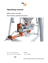 PFT CMP 4.0 User manual
-
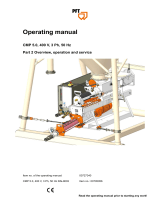 PFT CMP 5.0 User manual
-
JCB S2032E User manual
-
-
-
-
-
-

