Page is loading ...

HFC Enhance
®
NT/NB DFB RETURN PATH TRANSMITTER
1. Overview
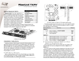
Figure #1 illustrates the HEFN**** DFB-based Return Path Transmitters.
2. Installation
1. Power off the NT/NB Node.
2. Open the NT/NB Node; locate the existing return transmitter module in the optical section of the node. The return path
transmitter is located on the left side of the node, underneath the Fiber Management Tray.
3. Swing the Fiber Management Tray up to provide access to the return transmitter(s).
4. Disconnect the fi ber connector and then remove the existing return transmitter and replace it with the new HEFN****
Return Path Transmitter provided. Secure the return path transmitter by tightening the captive screws located on the
module. The RF input connection to the return path transmitter is made at the bottom of the return transmitter modules
DB-style connector.
5. Reconnect the appropriate fi ber connector to the new return transmitter. Dress the fi ber inside the node to prevent
it being damaged or pinched when the node is closed. (Note: Always clean the ber connectors to prevent
contamination.Alsoensurethattheberconnectorsareofthesametype,mismatchingberconnectorscan
causelowsignallevelordamagetotheberconnectorfaces).
6. Tilt the Fiber Management Tray back down into the node and secure.
7. Power the NT/NB Node back on.
8. Optical output power of the HEFN**** Return Path Transmitter can be measured at the 1V/mW OPT PWR Test Point on
the transmitter. Be sure to ground the ground lead of the multimeter to a ground in the node when monitoring these
test points.
9. RF input level into the return path transmitter can be measured at the -20 dB Test Point on the transmitter.
10. The transmitter also features an LED which illuminates GREEN when the transmitter status is nominal and RED when the
transmitter has a fault.
11. When everything is connected and the unit is powered, adjust the level of the transmitter for optimum RF drive level
(see Section #3).
HFC Enhance
®
– NT/NB DFB Return Path Transmitter Installation & Operation Manual Page 1 of 3
HFC Enhance
®
– NT/NB DFB Return Path Transmitter Installation & Operation Manual
Figure#1HEFN****ReturnPathTransmitter

3. SettingLaserDriveLevels
The HFC Enhance Return Path Transmitters for the NT/NB Nodes have been optimized based on the assumption that they
will be driven with 37 MHz of loading
(1)
.
12. The Return Path can be optimized by injecting a carrier at the node port of level “EXPECTED RETURN CARRIER LEVEL
+20 dB” (Note:EXPECTEDRETURNCARRIERLEVELisasystemspecicdesignspecication) and adjust padding
in the return path until the level measured on the return transmitter’s -20 dB test point equals the value (in dBmV) that
is noted on the label beside the return path transmitter’s -20 dB RF test point. The label location is adjacent to the test
point on the transmitter as shown in Figure #2 below. The reverse pad locations for each port are shown in Figure #3
below. Further, there is a pad that is common to all ports in front of the transmitter in the optical lid.
(1)
The optimum operating point for the transmitter is selected as the point that is 5 dB above the location where the noise side of the
NPR curve crosses 41 dB. The NPR curve is generated using 37 MHz of noise loading and the per carrier power level is calculated
assuming that the total power is calculated at the optimum operating point is spread across 6 carriers.
Figure#2LaserDriveLevelLabel
HFC Enhance
®
– NT/NB DFB Return Path Transmitter Installation & Operation Manual
Figure#3NT/NBNodeOverview
HFC Enhance
®
– NT/NB DFB Return Path Transmitter Installation & Operation Manual Page 2 of 3

HFC Enhance
®
– NT/NB DFB Return Path Transmitter Installation & Operation Manual
Service&Support
Contact ATX Networks
Please contact ATX Technical Support for assistance with any ATX products. Please contact ATX Customer Service to obtain
a valid RMA number for any ATX products that require service and are in or out-of-warranty before returning a failed module
to the factory.
RFProducts
(MAXNET, SignalOn, HFC Enhance, PCI Filters, Q-Series, SCN, SMAC, FiberLinx)
TECHNICALSUPPORT
Tel: (905) 428-6068 – press *3 then press 2
Toll Free: (800) 565-7488 – press *3 then press 2 (USA & Canada only)
Email: [email protected]
CUSTOMERSERVICE
ATX Networks
1-501 Clements Road West
Ajax, ON L1S 7H4 Canada
Tel: (905) 428-6068 – press *1
Toll Free: (800) 565-7488 – press *1 (USA & Canada only)
Fax: (905) 427-1964
Toll Free Fax: (866) 427-1964 (USA & Canada only)
Email: [email protected]
Web: www.atxnetworks.com
WarrantyInformation
All of ATX Networks’ products have a 1-year warranty that covers manufacturer’s defects or failures.
HFC Enhance
®
– NT/NB DFB Return Path Transmitter Installation & Operation Manual
HFC Enhance
®
– NT/NB DFB Return Path Transmitter Installation & Operation Manual Page 3 of 3
SignalOn
®
Series, MAXNET
®
, HFC Enhance
®
, PCI Filters
®
, Q-Series
®
& FiberLinx
®
are registered trademarks of ATX in the United States and/or other countries. SMAC
SM
is a
service mark of ATX in the United States and/or other countries. Products or features contained herein may be covered by one or more U.S. or foreign patents. Other non-ATX
product and company names in this manual are the property of their respective companies.

ATX Networks
1-501 Clements Road West, Ajax, ON L1S 7H4 Canada
Tel: 905.428.6068 | Toll Free: 800.565.7488 | [email protected]
ISO
9001
REGIST ERE D
© 2018 ATX Networks
Printed in Canada
Information in this document is subject to change without notice.
www.atxnetworks.com
Rev. 05/18 (ANW0777 )
/


