Page is loading ...

REMOTE CONTROL CR-16A
OVP
INV
PWR.
SAV.
GRID
UVP OLP OTP
20
40
60
80
100
Low
Norm.
High
BATTERY
VOLTAGE POWER (%)
OUTPUT
REMOTE CONTROL CR-16B
FLOAT
ABSORPTION
BULK
OVP
INV
PWR.
SAV.
GRID
UVP OLP OTP
CHG
20
40
60
80
100
Low
Norm.
High
BATTERY
VOLTAGE POWER (%)
OUTPUT
33
55
2
11
44
89
76
Ø4.5
77
10.5
6.5 72
JP1
8
Aux port
AUX
6
7
Phone Jack
Connector
!
A
6
1
B
6
1
9.6±0.2
9.6±0.2
12.4±0.3
6.5±0.2
14.6±0.3
3.1±0.2
12.4±0.3
6.5±0.2
14.6±0.3
3.1±0.2
A
6
5
4
3
2
1
WIRE COLOR
YELLOW
BLUE
GREEN
WHITE
BLACK
RED
B
6
5
4
3
2
1
User Guide For CR-16 Remote Control
1. Features
• Battery bank voltage display
• Output power display
• Error condition indicatorHigh Battery, Low Battery, Over Temperature, Over Load conditions
• Action condition indicatorINV, GRID, POWER SAVING, CHARGING STATUS
• Connection failure notification
2. Specification
• Input Voltage10.5 ~ 66 Vdc
• Operating Temperature Range0 ~ 40
• Storage Temperature Range- 30 ~ 70
• Stand-By Current Draw< 80mA
• Applicable ModelsCR-16A – SP Series
CR-16B – SC & SL Series
NoteGrid LED is only functional when connecting SP series with TR-40.
3. Introduction
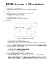
3-1. Front Panel Introduction
Figure 1. CR-16 Front Panel Introduction
Power ON/OFF Button
Power ON/OFF button is to turn the inverter on or off.
Charging Status LED (BULK / ABSORPTION / FLOAT) shows the charging status(Only
applicable to SL series)
• BULKWhen the battery is in low voltage status, the battery is charged at constant current by
maximum charge current.
• ABSORPTIONWhen the battery is near fully charged, the battery keeps charging by constant
voltage mode.
3-2. Rear Panel Introduction
Figure 2. CR-16 Rear Panel Introduction (Unit: mm [inch]) Figure 3. Aux Connector (Unit: mm [inch])
Aux port
The connector (Fig.3) connected to AUX wire (AWG 14 or 16) must connected with 12V / 0.5A
fuse.
• Ignition Lockout function – The ignition lockout function is to turn OFF the Inverter when the
auxiliary input wiring is connected to the ACC with 12 Volts.
• Return Override Function – The Return Override Function is to turn ON the inverter when the
auxiliary input wiring is connected to the reversed gear shift with 12 Volts.
Phone Jack Connector
1. Before connection, please make sure to switch the inverter to REMOTE mode. (For SP series)
(Fig.4)
Figure 4. SP series remote position
2. Connect the RJ-11 cable between CR-16 remote and the inverter.
Figure 5. Phone Jack Connector (Unit: mm [inch])
WARNING!
DO NOT use standard telephone cable.
JP1The JP1 is to set either Return Override Function or Ignition lockout function.
• JP1 jumper “Short” - Return Override Function
Return Override Function – The Return Override Function is to turn ON the inverter when the
auxiliary input wiring is connected to the reversed gear shift with 12 Volts.
• JP1 jumper “Open” – Ignition Lockout Function
Ignition Lockout function – The ignition lockout function is to turn OFF the inverter when the
auxiliary input wiring is connected to the ACC with 12 Volts.
• The connector which is connected to AUX power must use with 12V / 0.5A fuse.
Notedefault mode is Open.
• FLOATWhen the battery is fully charged, this state maintains the battery at 100% charge
without overcharging or damaging the battery.
Please refer to the detail information in SL series user manual accordingly.
Output power indicator
Output power indicator shows the power draw from the power inverter by the load. Ideally, the
output power indicator should remain in the green & orange area of the bar chart.
If the output power indicator is up to the red area, the OLP LED will flash and the inverter will shut
down.
Battery voltage indicator
Battery voltage indicator will move up and down as the battery voltage changes. Ideally, the
voltage should remain in the green area of the bar chart. If the voltage goes into the red area at
the top and bottom of the bar chart, inverter may shut down.
Other Indicators
• OVP (Over voltage protection indicator)
It indicates that the power inverter shuts down because its input voltage is above limit voltage.
• UVP (Under voltage protection indicator)
The under voltage indicator is to indicate the inverter shut down due to under voltage protection.
• OLP (Overload protection indicator)
The overload indicator is to indicate the inverter shut down due to short circuit or overload
protection.
• OTP (Over temperature protection indicator)
The over temp indicator is to indicate the inverter shut down due to over temperature protection.
Once the inverter cools down, the indicator will turn off automatically.
• INV. indicator
The INV. indicator is to indicate the inverter is ready.
• PWR. SAV. IndicatorPower saving functions are described below
• GRID indicator
The GRID indicator is to indicate the AC Grid is connected to inverter.
(For SP seriesOnly functional when connecting SP Series with TR-40)
• CHG indicator
The CHG indicator is to indicate the battery charging status (Only applicable to SL series).
Power ON/OFF Button
Charging Status LED
Output power indicator
Battery voltage indicator
LED
Trigged signal
AUX
JP1
Inverter
Status
Open OFF
OFF
ON
ON
Open
Short
Short
0
1
0
1
Solid
Flashing
Off
Ready
Active
Inactive
ON
OFF
Meaning Inverter Output
Other Indicators
1
1
6
8
7
3
4
5
2
4
52
3
22±1.0
10±0.5
Ø4.5±0.3
No.33, Sec. 2, Renhe Rd., Daxi Dist., Taoyuan City 33548, Taiwan
Phone+886-3-3891999 FAX+886-3-3802333
http// www.cotek.com.tw
2016.07._A0
EN
1 2
3 4

REMOTE CONTROL CR-16A
OVP
INV
PWR.
SAV.
GRID
UVP OLP OTP
20
40
60
80
100
Low
Norm.
High
BATTERY
VOLTAGE POWER (%)
OUTPUT
REMOTE CONTROL CR-16B
FLOAT
ABSORPTION
BULK
OVP
INV
PWR.
SAV.
GRID
UVP OLP OTP
CHG
20
40
60
80
100
Low
Norm.
High
BATTERY
VOLTAGE POWER (%)
OUTPUT
33
55
2
11
44
89
76
Ø4.5
77
10.5
6.5 72
JP1
8
Borne AUX
AUX
6
7
Phone Jack
Connector
!
A
6
1
B
6
1
9.6±0.2
9.6±0.2
12.4±0.3
6.5±0.2
14.6±0.3
3.1±0.2
12.4±0.3
6.5±0.2
14.6±0.3
3.1±0.2
A
6
5
4
3
2
1
Couleur fil
Jaune
Bleu
Vert
Blanc
Noir
Rouge
B
6
5
4
3
2
1
Schéma 4 – Position « REMO » onduleurs SP
Signal AUX
1
0
1
Ouvert
Ouvert
Fermé
0 Fermé
OFF
OFF
ON
ON
JP1 Status onduleur
État
Allumé
Flashs
Éteint
Prêt
Actif
Inactif
ON
OFF
Signification Sortie onduleur
Manuel utilisateur
Panneau de commande à distance CR-16
1. Présentation
• Affichage de la tension batterie.
• Affichage de la puissance de sortie.
• Affichage des défauts (tension batterie haute, tension batterie basse, surchauffe, surcharge).
• Témoins mode de fonctionnement (INV, GRID, POWER SAVING, CHARGING STATUS).
• Notification en cas d’erreur de connexion.
2. Caractéristiques
• Plages de tension admissibles (alimentation) 10,5 à 66 V CC
• Plages de températures admissibles (fonctionnement) 0 à 40°C
• Plages de températures admissibles (stockage) -30°C à +70°C
• Consommation à vide < 80 mA
• Compatibilité
Onduleurs série SP 700 / 1000 / 1500 / 2000 / 3000 / 4000
Onduleurs-chargeurs série SL 2000 / 3000
NBindication GRID seulement sur les onduleurs de la série SP connectés à un kit TR-40.
3. Introduction
3-1. Présentation du panneau avant
Schéma 1 – Présentation du panneau avant
Interrupteur ON/OFFpermet de mettre en marche / d’arrêter l’onduleur.
Témoins d’état de charge (LED) pour onduleurs-chargeurs série SL exclusivement
BULKcharge à courant constant, au courant nominal max.
ABSORPTIONcharge à tension constante.
FLOATmaintien de charge.
Merci de vous reporter au manuel livré avec les appareils série SL pour plus de détails.
Puissance sortie CA en %affichage de la puissance de sortie CA (barres)un témoin lumineux
indique la puissance en pourcentage. Idéalement il doit rester en zone verte & orange. S’il atteint
la zone rouge, le témoin OLP (protection surcharge) clignote et l’onduleur s’arrête.
Tension batterieaffichage de la tension batterie (barres) un témoin lumineux indique le
niveau de tension de la batterie. Idéalement la tension doit rester en zone verte. Si les barres
rouges sont allumées (en zone basse ou haute), l’onduleur peut s’arrêter.
Autres témoins
• OVP – Tension batterie hautel’onduleur a été coupé en raison d’une sur-tension.
• UVP – Tension batterie bassel’onduleur a été coupé en raison d’une sous-tension.
• OLP – Surchargel’onduleur a été coupé en raison de surcharges. Ce témoin peut
également indiquer un court-circuit.
• OTP – Surchauffel’onduleur a été coupé en raison d’une surchauffe. Le témoin s’éteint
lorsque l’onduleur a refroidi.
• INV – Onduleurl’appareil est en mode onduleur.
• PWR. SAV – Mode économie d’énergie
• GRID – Réseaul’onduleur est branché sur une alimentation courant alternatif.
(Seulement sur les onduleurs de la série SP connectés à un kit TR-40).
• CHG – Témoin de charge de la batterie (pour onduleurs-chargeurs série SL exclusivement).
3-2. Présentation du panneau arrière
Schéma 2 – Panneau arrière Schéma 3 – Connecteur port AUX
Borne AUXutiliser un câble d’une section de 2,5 mm² ou 1,5 mm² (14-16 AWG) pour raccorder
le connecteur AUX (schéma 3) à la borne AUX. Protéger la connexion par un fusible 12 V / 0,5 A.
• Fonction « Ignition Lockout »arrêt de l'onduleur lorsque la borne AUX est raccordée au
régulateur de vitesse adaptif (Adaptive Cruise Control) et que la tension 12 Volt est présente.
• Fonction « ROF »marche de l'onduleur lorsque la borne AUX est raccordée à la position
marche arrière du levier de vitesse et que la tension 12 Volt est présente.
Prise type RJ
1. Sur les modèles SP exclusivement. Avant de raccorder la prise, s’assurer que l’interrupteur sur
l’onduleur est en position « REMO » (commande déportée), comme indiqué sur le schéma 4.
2. Utiliser le câble RJ-11 pour raccorder le panneau de commande CR-16 à l’onduleur.
Schéma 5 – Câble de connexion
ATTENTION!
Ne pas utiliser du câble téléphonique standard pour raccorder l’onduleur au panneau de
commande à distance.
Cavalier – JP1
Il permet de sélectionner les fonctions Marche/Arrêt de l’onduleur.
• Avec le cavalier – Fonction « ROF » : marche de l'onduleur lorsque la borne AUX est raccordée
à la position marche arrière du levier de vitesse et que la tension 12 Volt est présente.
• Sans le cavalier – Fonction « Ignition Lockout » : arrêt de l'onduleur lorsque la borne AUX est
raccordée au régulateur de vitesse adaptif (Adaptive Cruise Control) et que la tension 12 Volt est
présente.
• La connexion à la borne AUX doit être protégée par un fusible 12 V / 0,5 A.
Le panneau est livré avec JP1 ouvert.
Interrupteur ON/OFF
Témoins d’état de charge
Puissance sortie CA en %
Tension batterie
Autres témoins
1
1
3
4
5
2
8
6
7
4
52
3
22±1.0
10±0.5
Ø4.5±0.3
No.33, Sec. 2, Renhe Rd., Daxi Dist., Taoyuan City 33548, Taiwan
Phone+886-3-3891999 FAX+886-3-3802333
http// www.cotek.com.tw
2016.07._A0
FR
5 6
7
/