Page is loading ...

EN
TECHNICAL
MANUAL
Passion.Technology.Design.
Maxi 2-wire door entry monitor
Art. 6801W - Art. 6801W/BM

2
Description ....................................................................................... 3
Touch-sensitive button activation ..........................................................4
Buttons ...................................................................................................... 4
Indicator LED ............................................................................................ 4
Press and hold keys
.............................................................. 4
Automatic door opening on receipt of call (Doctor mode)...................4
Automatic answer (Hands-Free function) ..............................................4
Technical specifications ................................................................. 5
Installation ........................................................................................ 6
Installed in flush-mounted box art. 6817 ................................................6
Surface-mounted installation (Art. 6820 - optional) .............................. 7
Connections ..................................................................................... 8
Variant: connection of call repetition device art. 1122/A ......................8
Settings ............................................................................................ 9
Main and secondary door entry monitors .............................................9
Power supply management ..................................................................... 9
Configuring buttons ...................................................................... 10
Basic configuration ................................................................................10
Legend.....................................................................................................10
Advanced configuration ........................................................................11
Intercom call .....................................................................................11
Introduction ...............................................................................11
General intercom call: button programming ............................. 11
Intercom call to selective address: button programming ..........12
Selective intercom address .......................................................12
Assigning selective address ......................................................12
Deleting the selective address of the door entry monitor..........12
Generic actuator, coded actuator ..................................................... 13
Generic actuator: button programming .................................... 13
Coded actuator: button programming......................................13
Other functions: button programming ..............................................14
Programming range ..........................................................................14
LED/alarm/lock-release/actuator programming ...............................15
Changing the ringtone ......................................................................15
Programming reset ...........................................................................16
System performance and layouts ................................................ 16
Addressing table ............................................................................ 17
Table of contents
Warning
Intended use
This Comelit product has been designed and manufactured for use in the creation of audio and video communication systems in residential,
commercial, industrial and public buildings.
Installation
All activities connected to the installation of Comelit products must be carried out by qualified technical personnel, with careful observation of the
indications provided in the Manuals / Instruction sheets supplied with those products.
Wires
Disconnect the power supply before carrying out any operations on the wiring.
Use wires with a cross-section suited to the distances involved, observing the instructions provided in the system manual.
We advise against running the system wires through the same duct as power cables (230V or higher).
Safe usage
To ensure Comelit products are used safely:
• carefully observe the indications provided in the Manuals / Instruction sheets,
• make sure the system created using Comelit products has not been tampered with / damaged.
Maintenance
Comelit products do not require maintenance aside from routine cleaning, which should be carried out in accordance with the indications provided
in the Manuals / Instruction sheets.
Any repairs must be carried out:
• for the products themselves, exclusively by Comelit Group S.p.A.,
• for the systems, by qualified technical personnel.
Disclaimer
Comelit Group S.p.A. does not assume any responsibility for
• any purpose other than the intended use,
• failure to observe the indications and warnings contained in this Manual / Instruction sheet.
Comelit Group S.p.A. reserves the right to change the information provided in this Manual / Instruction Sheet at any time and without prior notice.

3
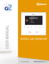
Description
1. Microphone
2. 7’’ LCD screen
3. Touch-sensitive buttons (Function)
4. Touch-sensitive buttons (Adjustment)
5. Function buttons
6. CV6 position A = contact IN1-IN2 > LED (Default)
CV6 position B = contact CFP2-IN1 > ALARM / LOCK-RELEASE / ACTUATOR
7. CV1 CV2 Jumper to be removed in case of separate power supply
8. CV5 Jumper for video closure. In systems with more than one door entry monitor connected in cascade, only the door entry
monitor furthest away must have CV5 closed
9. S2 DIP-switches
Microswitches for button and function programming
DIP 1-2-3-4 for button function programming
DIP 5-6 access to programming
DIP 7 for power supply voltage management. Paragraph on page 9
DIP 8
for setting main and secondary door entry monitor. Paragraph
on page 9
10. Terminal block for system connection:
CFP1 CFP2 Floor door call input
S+ S- Additional ringtone
IN1 IN2 Input (programmable)
- + Power supply
L L BUS line connection
11. S1 DIP-switches
Microswitches for assigning user code according to “Addressing table" on page 17
6.
9.
10.
11.
7.
8.
1.
3. 4.
5.
2.
The door entry monitor can be used in Simplebus2 audio/video systems.
Maxi 6801W is a colour monitor equipped as standard with 8 function buttons and 6 adjustment buttons.
Maxi 6801W/BM is a colour monitor with 8 function buttons and 6 adjustment buttons, equipped with a magnetic amplification
system for hearing aid devices.

4
Touch-sensitive button activation
f Touch to activate the function keys.
f Press the desired button once to activate the function
associated with it
Wait for approximately 1 sec. before pressing
the same button again. Pressing the same
button several times in quick succession will
cancel the command.
Buttons
Audio activation
Lock-release activation
Buttons 1-2-3-4 (programmable)
Self activation (programmable)
Ringtone activation in silent mode
(Privacy mode)
Audio volume adjustment
Call volume adjustment
Increase / Decrease value
Contrast adjustment
Brightness control
Indicator LED
continuous flashing = incoming call
LED steady in call = communicating
LED steady in standby = Automatic answer mode
(Hands-free mode) enabled
continuous flashing = incoming call
1 flash = confirm lock-release
4 flashes = programming successful
10 flashes = programming error
LED steady = ringtone in silent mode
(Privacy mode)
3 flashes (every 5 s.) = Automatic door opening on
receipt of call mode (Doctor mode) enabled
slow flashing = programming
4 flashes = device busy
Press and hold keys (Disabled by default from firmware version 1.4.0)
Pressing and holding keys adds further functions to the door entry monitor.
Carry out the procedure described below to enable - or disable, depending on the factory setting - the press and hold
feature:
√ Door entry monitor in standby.
1. Take note of the S2 DIP-switch settings.
2. Enter programming mode by setting S2 DIP-switches 1, 3, 5 to ON.
3. Press
to enable (or press to disable).
4. Make sure the key flashes 4 times and the confirmation tone is emitted.
5. Restore the initial configuration of the S2 DIP-switches.
Once the enabling procedure is complete, you will be able to enable the following functions:
Automatic door opening on receipt of call (Doctor mode)
f Press and hold (4 sec.) the programmed button (default: Key 3) to enable/disable the function.
Automatic answer (Hands-Free function)
f Press and hold (4 sec.) the audio activation button to enable/disable the function.

5
Technical specifications
GENERAL DATA 6801W 6801W/BM
Product height (mm) 124 124
Product width (mm) 223 223
Product depth (mm) 25 25
Product weight (g) 650 650
Product colour White RAL9003, base grey RAL7001 White RAL9003, base grey RAL7001
Material ABS, Glass ABS, Glass
Flush mounting Yes, with specific accessory Yes, with specific accessory
Surface mounting Yes, with specific accessory Yes, with specific accessory
Desk base mounting Yes, with specific accessory Yes, with specific accessory
COMPATIBLE SYSTEMS
Simplebus 2 audio/video with
power supply unit art. 4888C
Yes Yes
Simplebus 2 audio/video with
power supply unit art. 1210/1210A
Yes Yes
Simplebus 2 audio/video kit with
power supply unit art. 1209
Yes Yes
DISPLAY SPECIFICATIONS
Size (inches) (") 7 7
Aspect ratio 16:9 16:9
AUDIO SPECIFICATIONS
Microphone 4 mm (Ø), Omnidirectional 4 mm (Ø), Omnidirectional
Loudspeaker 80 mm (Ø), 80 Ohm, 1W 80 mm (Ø), 80 Ohm, 1W
Technologies implemented Full-Duplex Full-Duplex
Magnetic induction system No Yes
ELECTRICAL SPECIFICATIONS
Type of power supply Power supply via video entry bus Power supply via video entry bus
Power supply voltage 22 to 34 VDC (Bus) 22 to 34 VDC (Bus)
Absorption in standby (W) 1 1
Maximum absorption (W) 11.2 11.2
HARDWARE CHARACTERISTICS
Type of buttons Capacitive Capacitive
Service buttons Lock-release, Answer, Silent, Door open Lock-release, Answer, Silent, Door open
No. of programmable buttons for
additional functions
4 4
Terminals L L - + CFP1 CFP2 S+ S- In1 In2 L L - + CFP1 CFP2 S+ S- In1 In2
Removable terminals Yes Yes
Number of outputs (no.)
1 1
Number of inputs (no.) 2 2
SETTINGS
Loudspeaker volume Yes Yes
Mic volume Yes Yes
Ringtone volume Yes Yes
Screen brightness Ye s Yes
Screen colour Yes Yes
Screen contrast Yes Yes
ENVIRONMENTAL AND CONFORMITY SPECIFICATIONS
IP protection rating IP30 IP30
Operating temperature (°C) 5 to 40 5 to 40
Operating humidity (max RH - %) 25 to 75 25 to 75
Environmental class I I
Conformity and Certifications RoHS II - 2011/65/EU (EN 50581:2012), EMC
2014/30/EU (EN 61000-6-1:2007, EN 61000-6-
3:2007+A1:2011)
RoHS II - 2011/65/EU (EN 50581:2012), EMC
2014/30/EU (EN 61000-6-1:2007, EN 61000-6-
3:2007+A1:2011)

6
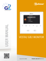
Installation
Installed in flush-mounted box art. 6817
ALTO
UP
HAUT
OBEN
3
160 cm
130 cm
2
223 mm
124 mm
1
6
L
max
= 10 cm
L
min
= 6 cm
5
3
1
5
7
9
4
2
6
8
4
2
1
CLACK !
2
9
1
2
8
1
2
7
1
2
DISASSEMBLY

7
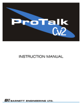
Surface-mounted installation (Art. 6820 - optional)
L
max
= 7 cm
L
min
= 6,5 cm
4
1
2
2
1
65
1
2
DISASSEMBLY
1
2
2
1
CLACK !
2
87
1
2
160 cm
130 cm
2 3
223 mm
124 mm
1

8
20 m MAX - Connect a single call repetition device for each user code.
20 m MAX - Use shielded cable for the connection and do not route the cables in the vicinity of heavy inductive loads
or power supply cables (230 V / 400 V).
Where multiple door-entry phones or monitor backplates have the same user code, connect the CFP button on one
only; all the devices will ring simultaneously.
For programming procedure details, see paragraph: “LED/alarm/lock-release/actuator programming" on page
15.
12/24V
AC/DC
1122/A
(12V)
C
N
O
N
C
-
+
+
-
1
P
F
C
2
P
F
C
1
IN IN
2
+
S
-
S
LL
20 m MAX - Connect a single call repetition device for each user code. If inductive loads are connected, the connection
of 470nF capacitance in parallel with the C-NO contacts of Art. 1122/A is recommended
Variant: connection of call repetition device art. 1122/A
Connections
1212/B
0
2
0
0
3
2
0
ALIMENTAZIONE
SUPPLEMENTARE
(SE NECESSARIA)
6801W
1214/2C
MONTANTE
VIDEOCITOFONICA
MONTANTE
VIDEOCITOFONICA
+
-
1
P
F
C
2
P
F
C
1
IN IN
2
+
S
-
S
CHIAMATA
FUORIPORTA
SUONERIA
SUPPLEMENTARE
1229
CV1CV2
LM
LM
OUT
L
IN
L
IN
L
OUT
L
INGRESSO
PROGRAMMABILE
CV6
A
B
LL
ADDITIONAL
POWER SUPPLY
(IF REQUIRED)
ADDITIONAL
RINGTONE
FLOOR DOOR
CALL
PROGRAMMABLE
INPUT
VIDEO ENTRY
RISER
VIDEO ENTRY
RISER

9
Settings
Main and secondary door entry monitors
In systems with power supply unit 1209, 1210 or 1210A, you can configure a maximum of 1 main door entry monitor (+3 powered
separately), while in systems with power supply unit 4888C you can configure a maximum of 2 main door entry monitors (+2
powered separately).
To configure the door entry monitor as the MAIN UNIT
S2
1 2 3 4 6 75 8
S2
1 2 3 4 6 75 8
, set DIP 8 of S2 to OFF
S2
1 2 3 4 6 75 8
S2
1 2 3 4 6 75 8
To configure a door entry monitor as a SECONDARY UNIT
S2
1 2 3 4 6 75 8
S2
1 2 3 4 6 75 8
, set DIP 8 of S2 to ON
S2
1 2 3 4 6 75 8
S2
1 2 3 4 6 75 8
Power supply management
For correct power supply management, set S2 DIP 7 in accordance with the type of system and its configuration:
• in systems with power supply units 1209, 1210 and 1210A: set S2 DIP 7 to ON.
• in systems with power supply unit 4888C set S2 DIP 7 to OFF for SECONDARY door entry monitors; for MAIN door entry
monitors follow the instructions illustrated as examples in the figure.
A. 1 main door entry monitor
B. 2 main door entry monitors
C. 3 main door entry monitors, 1 of which is powered separately
A
B
C
4888C
S2
1 2 3 4 6 75 8
S2
1 2 3 4 6 75 8
S2
1 2 3 4 6 75 8
S2
1 2 3 4 6 75 8
S2
1 2 3 4 6 75 8
S2
1 2 3 4 6 75 8
S2
1 2 3 4 6 75 8
S2
1 2 3 4 6 75 8
S2
1 2 3 4 6 75 8
S2
1 2 3 4 6 75 8
S2
1 2 3 4 6 75 8
S2
1 2 3 4 6 75 8

10
Configuring buttons
By default the buttons control the functions in row A (“Basic configuration” table).
It is possible to change the default configuration of the buttons by changing the positions of S2 DIP-switches 1-2-3-4 on the
rear of the door entry monitor to one of the combinations (B-P) suggested in the table. All the buttons will change function.
Basic configuration
Legend
ACT
Actuator
AI
Self Activation
AP
Lock-release
AUDIO
Audio
CCP
Call to main switchboard [not available in KIT systems]
CCS
Call to secondary switchboard [not available in KIT systems]
D
Automatic door opening on receipt of call (Doctor mode)
INT
General or selective programmable intercom. Single-family call default for Kit and Simplebus2
INTb
Two-family intercom call [for KIT only]
K
Caretaker door-entry phone call
PAN
Priority call to switchboard [not available in KIT systems]
NULL
No function
PROG
With these S2 DIP-switch settings, the buttons control the programmed functions as in the "Advanced
configuration".
S2 DIP-switch
DIP 1 DIP 2 DIP 3 DIP 4
A
OFF OFF OFF OFF
AUDIO AP CCS ACT D PAN AI
B
ON OFF OFF OFF AUDIO AP ACT INT INTb D AI
C
OFF ON OFF OFF AUDIO AP INT INTb ACT CCS AI
D
ON ON OFF OFF AUDIO AP ACT CCP PAN K CCS
E
OFF OFF ON OFF AUDIO ACT ACT ACT ACT ACT ACT
F
ON OFF ON OFF AUDIO AP INT CCS CCP INTb ACT
G
OFF ON ON OFF AUDIO AP AI K CCS CCP D
H
ON ON ON OFF AUDIO AP INTb AI INT PAN INT
I
OFF OFF OFF ON AUDIO AP CCS D AI INT PAN
J
ON OFF OFF ON AUDIO AP K PAN CCP AI CCS
K
OFF ON OFF ON AUDIO AP CCP PAN ACT INT K
L
ON ON OFF ON AUDIO AP PAN CCS K ACT CCP
M
OFF OFF ON ON AUDIO AP D INT ACT AI INTb
N
ON OFF ON ON AUDIO AP INT INT INT INT INT
P
OFF ON ON ON NULL NULL NULL NULL NULL NULL NULL
ON ON ON ON
PROG

11
Advanced configuration
If the basic configuration settings (A-P) do not reflect requirements, the buttons can be programmed dierently by carrying out
the steps below.
After programming, set S2 DIP-switches 1-2-3-4 (PROG) to ON. With these DIP-switch settings, the buttons manage the
programmed functions.
The buttons that are NOT programmed control the functions in row A (“Basic configuration” table).
Intercom call
General intercom call: button programming
Introduction
1. Take note of the S1 DIP-switch settings.
2. To enter programming mode, set S2 DIP-switch 6 to ON.
» the LED
flashes
S2
3. Refer to the table “Basic configuration" to identify a DIP-switch combination in which the intercom function (INT or
INTb) corresponding to the button you want to program appears, then set the S2 DIP-switches.
Example: For button 1= Intercom (INT) set S2 DIP-switches 1-2-3-4 as specified in row "C" in the "Basic configuration"
table.
4.
Set the S1 DIP-switches according to the call address of the desired apartment. See
“Addressing table" on page 17
5. Press and release the button to be associated with the function.
» Correct procedure indication: the LED
flashes for a few seconds and a confirmation tone sounds.
√ when programming using several buttons, continue programming the next key by repeating the process from step 4
onwards.
6. Exit programming mode by setting S2 DIP-switch 6 to OFF.
» LED
switches off
S2
7. Set S2 DIP-switches 1-2-3-4 to ON.
8. Return S1 DIP-switches to the original combination.
By "General intercom call" we mean a call from a door-entry phone/door entry monitor to the devices (in the same apartment
or another apartment) identified by the call address for the apartment (user code).
By "Intercom call to selective address" we mean a call from a door-entry phone/door entry monitor to a device (or several)
identified by a specific (selective) address which is dierent from the call address for the apartment (user code).
General and selective intercom calls CANNOT be used together on the same riser!

12
Intercom call to selective address: button programming
1. The steps illustrated in paragraph “Assigning a selective address” should be carried out on the devices involved in the
intercom call.
2.
Take note of the S1 DIP-switch settings.
3. To enter programming mode, set S2 DIP-switch 6 to ON.
» the LED
flashes
S2
4. Refer to the table “Basic configuration" to identify a DIP-switch combination in which the intercom function (INT or
INTb) corresponding to the button you want to program appears, then set the S2 DIP-switches.
5. Use the S1 DIP-switches to set the selective address of the device you wish to call. Table B.
For group calls, simultaneously set the desired selective addresses (max. 3) to ON.
6. Press and release the button to be associated with the function.
» Correct procedure indication: the LED
flashes for a few seconds and a confirmation tone sounds.
√ when programming using several buttons, continue programming the next key by repeating the process from step 5
onwards.
7. Exit programming mode by setting S2 DIP-switch 6 to OFF.
» LED
switches off
S2
8. Set S2 DIP-switches 1-2-3-4 to ON.
9. Return S1 DIP-switches to the original combination.
Assigning selective address
Selective intercom address
Deleting the selective address of the door entry monitor
(Steps only need to be carried out for “Intercom call to selective address” programming)
1. 2. 3. 4.
Take note of the
S1, S2 settings and
restore them when
programming is
complete.
S1: Set an address.
(Table B) Example: 3
S1
S2: Set the DIP-switches
as shown in the figure.
S2
1
x4
x10
OK prog:
KO prog:
x4
x10
OK prog:
KO prog:
1. 2. 3.
Take note of the
S1, S2 settings and
restore them when
programming is
complete.
Set the DIP-switches as shown in the figure.
S1
S2
x4
x10
OK prog:
KO prog:
x4
x10
OK prog:
KO prog:
TABLE B
Code S1 DIP-switch ON Code S1 DIP-switch ON Code S1 DIP-switch ON
1 1 4 4 7 7
2 2 5 5 8 8
3 3 6 6
Assign one of the 8 addresses available in TABLE B to each device involved in the intercom call.
• You can assign the same selective intercom address to a maximum of 3 devices.

13
Generic actuator, coded actuator
Coded actuator: button programming
Generic actuator: button programming
1. Take note of the S1 DIP-switch settings.
2. To enter programming mode, set S2 DIP-switch 6 to ON.
» the LED
flashes
S2
3. Refer to the table “Basic configuration" to identify a DIP-switch combination in which the actuator function (ACT)
corresponding to the button you want to program appears, then set the S2 DIP-switches.
4. Set all the S1 DIP-switches to the ON position.
S1
5. Press and release the button to be associated with the function.
» Correct procedure indication: the LED
flashes for a few seconds and a confirmation tone sounds.
6. Exit programming mode by setting S2 DIP-switch 6 to OFF.
» LED
switches off
S2
7. Set S2 DIP-switches 1-2-3-4 to ON.
8. Return S1 DIP-switches to the original combination.
1. Take note of the S1 DIP-switch settings.
2. To enter programming mode, set S2 DIP-switch 6 to ON.
» the LED
flashes
S2
3. Refer to the table “Basic configuration" to identify a DIP-switch combination in which the actuator function (ACT)
corresponding to the button you want to program appears, then set the S2 DIP-switches.
4.
Set the S1 DIP-switches with the desired code, according to “Addressing table" on page 17
5. Press and release the button to be associated with the function.
» Correct procedure indication: the LED
flashes for a few seconds and a confirmation tone sounds
6. Exit programming mode by setting S2 DIP-switch 6 to OFF.
» LED
switches off
S2
7. Set S2 DIP-switches 1-2-3-4 to ON.
8. Return S1 DIP-switches to the original combination.

14
Other functions: button programming
Programming range
1. 2. 3. 4.
Min. address
S1
Set a code
“Addressing
table" on page
17
S2
1
x4
OK prog:
x4
KO prog:
S2
Max. address
2
Cancellation
S1
S2
2 sec.
1.
Enable
1
2 sec.
x10
x10
OK prog:
KO prog:
Disable
2
2 sec.
Take note of the S2, S1 settings and restore on completion of programming
1. To enter programming mode, set S2 DIP-switch 6 to ON.
» the LED
flashes
S2
2. Refer to the table “Basic configuration" to identify a DIP-switch combination in which the desired functions
corresponding to the buttons you want to program appear, then set the S2 DIP-switches.
Example: For button 4= Self Activation (AI) and button 5 = Call to Secondary Switchboard (CCS), set S2 DIP-switches
1-2-3-4 as specified in row M in the "Basic configuration" table.
3. Press and release the buttons involved in the change.
» Correct procedure indication: the LED
flashes for a few seconds and a confirmation tone sounds.
4. Exit programming mode by setting S2 DIP-switch 6 to OFF.
» LED
switches off
S2
5. Set S2 DIP-switches 1-2-3-4 to ON.
When the procedure is complete, restore the initial DIP-switch combination.

15
Take note of the S2, S1 settings and restore on completion of programming
LED/alarm/lock-release/actuator programming
1. 2. 3. 4.
Input IN 1- IN 2
LED (default)*
S2
1
x4
OK prog:
x10
KO prog:
S2
Input CFP2 - IN 1
ALARM*
2
Input CFP2 - IN 1
LOCK-RELEASE*
S2
1
Input CFP2 - IN 1
CODED ACTUATOR*
S1
Set a code
“Addressing
table" on page
17
2
Input CFP2 - IN 1
GENERIC ACTUATOR*
S1
2
* See “Advanced configuration" on page 11.
Changing the ringtone
1. Press and hold for 6 sec.
» a confirmation tone is emitted
» the LED
flashes
√ the procedure can only take place while the system is in standby; otherwise the LED will flash 4 times to inform the
user that the system is busy
2. Press and release
Once (1 confirmation tone is emitted) to change the ringtone for calls from the external entrance panel.
twice (2 confirmation tones are emitted) to change the ringtone for calls from the switchboard.
3 times (3 confirmation tones are emitted) to change the ringtone for intercom calls made from the door entry monitor.
4 times (4 confirmation tones are emitted) to change the floor door call ringtone.
Any further pressing of the button repeats the sequence described above.
3. Press and release
to scroll through the available ringtones in sequence.
4. Press the
buttonto confirm selection of the last ringtone heard and to exit change door entry monitor ringtone mode.
» a confirmation tone is emitted
» LED
switches o
When the procedure is complete, restore the initial DIP-switch combination.

16
Programming reset
Factory settings:
• Button functions for the S2 DIP-switches 1-2-3-4 combination
• Intercom address absent
• Range function and min./max. addresses absent
• Ringtone reset
• Input IN 1 - IN 2 > LED (default)
• “Automatic answer”, “Automatic door opening on receipt of call” and “Silent” mode disabled
System performance and layouts
For further information of system performance and to view installation layouts, click on the system type that best meets your
requirements:
• Simplebus2 audio/video kit with power supply unit art. 1209 for the creation of audio-video systems for individual residences
• Simplebus2 audio/video with power supply unit art. 1210/1210A for the creation of audio-video systems for small apartment
blocks
• Simplebus2 audio/video with power supply unit art. 4888C for the creation of audio-video systems for residential complexes
1. 2. 3.
Take note of the
S1, S2 settings and
restore them when
programming is
complete.
Set the DIP-switches as shown in the figure.
S1
S2
2
x4
x10
OK prog:
KO prog:
x4
x10
OK prog:
KO prog:

* NOTE: Code 240 is reserved for the porter switchboard
Code
DIP-switch
ON
1 1 31 1,2,3,4,5 61 1,3,4,5,6 91 1,2,4,5,7 121 1,4,5,6,7 151 1,2,3,5,8 181 1,3,5,6,8 211
1,2,5,7,8
2 2 32 6 62 2,3,4,5,6 92 3,4,5,7 122 2,4,5,6,7 152 4,5,8 182 2,3,5,6,8 212
3,5,7,8
3 1.2 33 1.6 63 1,2,3,4,5.6 93 1,3,4,5,7 123 1,2,4,5,6.7 153 1,4,5,8 183 1,2,3,5,6.8 213
1,3,5,7,8
4 3 34 2.6 64 7 94 2,3,4,5,7 124 3,4,5,6,7 154 2,4,5,8 184 4,5,6,8 214
2,3,5,7,8
5 1.3 35 1,2,6 65 1.7 95 1,2,3,4,5.7 125 1,3,4,5,6.7 155 1,2,4,5,8 185 1,4,5,6,8 215
1,2,3,5,7.8
6 2.3 36 3.6 66 2.7 96 6.7 126 2,3,4,5,6.7 156 3,4,5,8 186 2,4,5,6,8 216
4,5,7,8
7 1,2,3 37 1,3,6 67 1,2,7 97 1,6,7 127 1,2,3,4,5,6,7 157 1,3,4,5,8 187 1,2,4,5,6.8 217
1,4,5,7,8
8 4 38 2,3,6 68 3.7 98 2,6,7 128 8 158 2,3,4,5,8 188 3,4,5,6,8 218
2,4,5,7,8
9 1.4 39 1,2,3,6 69 1,3,7 99 1,2,6,7 129 1.8 159 1,2,3,4,5.8 189 1,3,4,5,6.8 219
1,2,4,5,7.8
10 2.4 40 4.6 70 2,3,7 100 3,6,7 130 2.8 160 6.8 190 2,3,4,5,6.8 220
3,4,5,7,8
11 1,2,4 41 1,4,6 71 1,2,3,7 101 1,3,6,7 131 1,2,8 161 1,6,8 191 1,2,3,4,5,6,8 221
1,3,4,5,7.8
12 3.4 42 2,4,6 72 4.7 102 2,3,6,7 132 3.8 162 2,6,8 192 7.8 222
2,3,4,5,7.8
13 1,3,4 43 1,2,4,6 73 1,4,7 103 1,2,3,6,7 133 1,3,8 163 1,2,6,8 193 1,7,8 223
1,2,3,4,5,7,8
14 2,3,4 44 3,4,6 74 2,4,7 104 4,6,7 134 2,3,8 164 3,6,8 194 2,7,8 224
6,7,8
15 1,2,3,4 45 1,3,4,6 75 1,2,4,7 105 1,4,6,7 135 1,2,3,8 165 1,3,6,8 195 1,2,7,8 225
1,6,7,8
16 5 46 2,3,4,6 76 3,4,7 106 2,4,6,7 136 4.8 166 2,3,6,8 196 3,7,8 226
2,6,7,8
17 1.5 47 1,2,3,4,6 77 1,3,4,7 107 1,2,4,6,7 137 1,4,8 167 1,2,3,6,8 197 1,3,7,8 227
1,2,6,7,8
18 2.5 48 5.6 78 2,3,4,7 108 3,4,6,7 138 2,4,8 168 4,6,8 198 2,3,7,8 228
3,6,7,8
19 1,2,5 49 1,5,6 79 1,2,3,4,7 109 1,3,4,6,7 139 1,2,4,8 169 1,4,6,8 199 1,2,3,7,8 229
1,3,6,7,8
20 3.5 50 2,5,6 80 5.7 110 2,3,4,6,7 140 3,4,8 170 2,4,6,8 200 4,7,8 230
2,3,6,7,8
21 1,3,5 51 1,2,5,6 81 1,5,7 111 1,2,3,4,6.7 141 1,3,4,8 171 1,2,4,6,8 201 1,4,7,8 231
1,2,3,6,7.8
22 2,3,5 52 3,5,6 82 2,5,7 112 5.67 142 2,3,4,8 172 3,4,6,8 202 2,4,7,8 232
4,6,7,8
23 1,2,3,5 53 1,3,5,6 83 1,2,5,7 113 1,5,6,7 143 1,2,3,4,8 173 1,3,4,6,8 203 1,2,4,7,8 233
1,4,6,7,8
24 4.5 54 2,3,5,6 84 3,5,7 114 2,5,6,7 144 5.8 174 2,3,4,6,8 204 3,4,7,8 234
2,4,6,7,8
25 1,4,5 55 1,2,3,5,6 85 1,3,5,7 115 1,2,5,6,7 145 1,5,8 175 1,2,3,4,6.8 205 1,3,4,7,8 235
1,2,4,6,7.8
26 2,4,5 56 4,5,6 86 2,3,5,7 116 3,5,6,7 146 2,5,8 176 5,6,8 206 2,3,4,7,8 236
3,4,6,7,8
27 1,2,4,5 57 1,4,5,6 87 1,2,3,5,7 117 1,3,5,6,7 147 1,2,5,8 177 1,5,6,8 207 1,2,3,4,7.8 237
1,3,4,6,7.8
28 3,4,5 58 2,4,5,6 88 4,5,7 118 2,3,5,6,7 148 3,5,8 178 2,5,6,8 208 5,7,8 238
2,3,4,6,7.8
29 1,3,4,5 59 1,2,4,5,6 89 1,4,5,7 119 1,2,3,5,6.7 149 1,3,5,8 179 1,2,5,6,8 209 1,5,7,8 239
1,2,3,4,6,7,8
30 2,3,4,5 60 3,4,5,6 90 2,4,5,7 120 4,5,6,7 150 2,3,5,8 180 3,5,6,8 210 2,5,7,8 *240
5,6,7,8
Addressing table
www.comelitgroup.com
Via Don Arrigoni, 5 - 24020 Rovetta (BG) - Italy
5 edizione 10/2020
code 2G40002593
CERTIFIED MANAGEMENT SYSTEMS
/