Comelit Icona 6601W/BM Technical Manual
- Category
- Door intercom systems
- Type
- Technical Manual
This manual is also suitable for
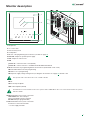
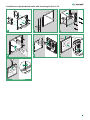
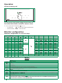
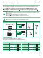
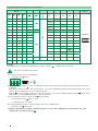
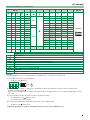
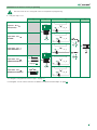
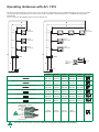
The Comelit Icona 6601W/BM is a color monitor with a 4.3" LCD screen, hands-free audio, and programmable soft-touch keys for various functions such as door release, privacy mode, volume adjustment, and more. It's compatible with Comelit Simplebus 2 systems and can be used in both single-family and multi-family installations.
The Comelit Icona 6601W/BM is a color monitor with a 4.3" LCD screen, hands-free audio, and programmable soft-touch keys for various functions such as door release, privacy mode, volume adjustment, and more. It's compatible with Comelit Simplebus 2 systems and can be used in both single-family and multi-family installations.


-
 1
1
-
 2
2
-
 3
3
-
 4
4
-
 5
5
-
 6
6
-
 7
7
-
 8
8
-
 9
9
-
 10
10
-
 11
11
-
 12
12
-
 13
13
-
 14
14
-
 15
15
-
 16
16
-
 17
17
-
 18
18
-
 19
19
-
 20
20
-
 21
21
-
 22
22
-
 23
23
-
 24
24
-
 25
25
-
 26
26
-
 27
27
-
 28
28


Comelit Icona 6601W/BM Technical Manual
- Category
- Door intercom systems
- Type
- Technical Manual
- This manual is also suitable for
The Comelit Icona 6601W/BM is a color monitor with a 4.3" LCD screen, hands-free audio, and programmable soft-touch keys for various functions such as door release, privacy mode, volume adjustment, and more. It's compatible with Comelit Simplebus 2 systems and can be used in both single-family and multi-family installations.
Ask a question and I''ll find the answer in the document
Finding information in a document is now easier with AI
Related papers
-
Comelit 6601W and 6601W/BM Owner's manual
-
-
-
-
Comelit 6741W/BM Owner's manual
-
-
-
-
-
Other documents
-
Legrand IC7201 Installation guide
-
 Barnett Engineering CV2 User manual
-
Auta Avant HI-245 User manual
-
 urmet domus MT124-027 Technical Manual
-
Videx DIGITAL VX2200 System Manual
-
 urmet domus MT124-027 Technical Manual
-
Elvox 69PH Installer's Manual
-
Sensata ISOSLICE-4 User manual
-
Leviton 47000-PRT Quick Install Manual
-
Broadcom AV02-4275EN_UG_AFBR-8420Z_2014-01-21 User guide


