Page is loading ...

POWER 55
Images may differ from actual productEN
El producto real puede variar respecto a la imagen mostrada.ES
Le produit réel peut différer de l'illustration.FR
Motorized Wall Mounting System
UL10378
ULN #
POWER 55 = L3-UL10378-CON-072208vB
PN #
Manuel D’instructionsFR
Manual De InstruccionesES
Instruction ManualEN
Maximum screen size: 55”
Maximum weight 110 lbs - 50 KG
CAUTION: DO NOT EXCEED MAXIMUM LISTED
WEIGHT CAPACITY. SERIOUS INJURY OR PROPERTY
DAMAGE MAY OCCUR!

P2
WARNING! SEVERE PERSONAL INJURY AND PROPERTY DAMAGE CAN RESULT FROM IMPROPER
INSTALLATION OR ASSEMBLY. READ THE FOLLOWING WARNINGS BEFORE BEGINNING.
If you do not understand the instructions or have any concerns or questions, please contact a qualified installer. North
America residents can contact OmniMount customer service at 800.668.6848 or [email protected].
Do not install or assemble if the product or hardware is damaged or missing. If you require replacement parts, contact
OmniMount Customer Service at 800.668.6848 or [email protected]. International customers need to contact a local
distributor for assistance.
For wall mounted products: This product has been designed for use on a vertical wall constructed of wood studs or
masonry (solid concrete). Wood studs being defined as a wall consisting of a minimum of 2 x 4 inch studs with a maximum
of 24 inch stud spacing and a minimum of 16 inch stud spacing with a maximum of ¾ inch of wall covering (drywall, lath,
plaster). If you don’t know your wall type, or for assistance with other surfaces (metal studs, solid block and brick), contact
a qualified installer. For safe installation, the wall you are mounting to must support 4 times the weight of the total load. If
not, the surface must be reinforced to meet this standard. The installer is responsible for verifying that the wall
structure/surface and the anchors used in the installation will safely support the total load.
This product is not designed to support the load of a CRT or flat screen television. Do not use this product for any
application other than those specified by OmniMount.
This product may contain moving parts. Use with caution.
DO NOT EXCEED THE MAXIMUM WEIGHT CAPACITY FOR THIS PRODUCT.
¡ADVERTENCIA! LA INSTALACIÓN O EL MONTAJE INAPROPIADOS PUEDEN PROVOCAR LESIONES, DAÑOS
MATERIALES O INCLUSO LA MUERTE. ANTES DE COMENZAR, LEA LAS SIGUIENTES ADVERTENCIAS.
Si las instrucciones no le resultan claras o si tiene alguna duda o pregunta, comuníquese con un instalador calificado. Los
residentes de América del Norte pueden comunicarse con el servicio de Atención al cliente de OmniMount al
800.668.6848 o por escrito a [email protected].
Si el producto o el hardware está dañado o no se le envió alguna pieza, no realice la instalación ni el montaje. Si necesita
piezas de repuesto, comuníquese con el servicio de Atención al cliente de OmniMount al 800.668.6848 o por escrito a
[email protected]. Los clientes internacionales deberán comunicarse con un distribuidor local para recibir asistencia.
Produits s’installant au mur : Ce produit a été conçu pour une installation sur un mur vertical de maçonnerie (béton
massif) ou construit sur une charpente en bois. Une charpente en bois est une structure murale constituée avec des
pièces de colombage d’une épaisseur d’au moins 5 cm x 10 cm ayant un espacement de 41 cm à 61 cm et étant
recouverte d’un revêtement d’une épaisseur d’au moins 19 mm (cloison sèche, lattes, plâtre). Si vous avez un doute sur la
composition de votre mur ou si vous désirez des conseils concernant une autre surface (poutres métalliques, blocs massif
et briques), contactez un installateur qualifié. Pour que l'installation soit sécuritaire, le mur d'installation doit pouvoir
supporter 4 fois le poids de la charge appliquée. Si tel n'est pas le cas, la surface doit être renforcée en conséquence.
L'installateur doit s'assurer que la structure/surface du mur d'installation et les chevilles d'ancrage utilisées peuvent
supporter sans danger le poids de tous les équipements.
Ce produit n’est pas conçu pour supporter le poids d’un téléviseur à écran cathodique ou à écran plat.No utilice este
producto para ninguna aplicación que OmniMount no haya especificado.
Este producto puede contener componentes móviles. Úselo con precaución.
NO EXCEDA LA CAPACIDAD DE PESO MÁXIMA PARA ESTE PRODUCTO.
WARNING! – ENGLISH
¡ADVERTENCIA! – ESPAÑOL
AVERTISSEMENT! – FRANÇAIS
AVERTISSEMENT! SI CE PRODUIT N’EST PAS CORRECTEMENT INSTALLÉ OU ASSEMBLÉ, IL RISQUE DE
CAUSER DES BLESSURES GRAVES, VOIRE MORTELLES, AINSI QUE DES DOMMAGES MATÉRIELS
IMPORTANTS. AVANT DE COMMENCER, LISEZ LES AVERTISSEMENTS SUIVANTS.
Si vous ne comprenez pas les instructions, de même que si vous avez un doute ou des questions, veuillez contacter un
installateur qualifié. Les personnes qui résident en Amérique du Nord peuvent contacter le service à la clientèle
OmniMount au 800.668.6848 ou à [email protected].
Si vous découvrez que le produit est endommagé ou que des fixations sont manquantes ou endommagées, n’installez pas
le produit. Si vous avez besoin de pièces de rechange, contactez le service à la clientèle OmniMount au 800.668.6848 ou
à [email protected]. Les clients habitant hors de l’Amérique du Nord peuvent obtenir de l’aide auprès de leur
distributeur local.
Información acerca de los productos que se instalan en la pared: Este producto está diseñado para ser instalado en
paredes verticales con paneles de madera o mampostería (hormigón). Se define a los paneles verticales como una pared
que consiste de un mínimo de paneles de 5 cm x 10 cm con un espacio entre paneles máximo de 61 cm y un espacio
mínimo entre paneles de 41 cm, con un máximo de cobertura de pared (hoja de yeso, listón, yeso) de 19 mm. Si no está
seguro acerca del material de su pared o si desea obtener información sobre otras superficies (paneles de metal, bloques
sólidos o ladrillo), comuníquese con un instalador calificado. Para realizar una instalación segura, la pared elegida debe
ser capaz de soportar 4 veces el peso de la carga total. De lo contrario, deberá reforzar la superficie para que cumpla con
este requisito. El instalador es el responsable de comprobar que la estructura/superficie de la pared y los tacos que se
utilizan en la instalación soporten la carga total de manera segura.
Este producto no está diseñado para soportar la carga de un televisor CTR o de pantalla plana.
Ce produit ne doit pas être utilisé pour un usage autre que ceux spécifiés par OmniMount.
Ce produit peut contenir des pièces mobiles. Veuillez l'utiliser avec prudence.
NE DÉPASSEZ JAMAIS LA CAPACITÉ DE CHARGE MAXIMALE DE CE PRODUIT.

P3
TABLE OF CONTENTS
P35Warranty
P34Trouble Shooting
P31-33Remote Control Functions
P30Cable Management
P29Power
P27-28IR Receiver
P23-26Non-VESA Monitor Installation
P16-22VESA Monitor Installation
P15Slim TV Installation
P11-14Solid Concrete Wall Installation
P8-10Wood Stud Wall Installation
P7Symbol Key
P5-6Hardware List
P4Maximum Weight

P4
WEIGHT CAPACITY
CAUTION!
MAXIMUM SCREEN SIZE
55”
55”
55 in. (140cm)
MAXIMUM SCREEN SIZE
TAMAÑO DE PANTALLA MÁXIMO
TAILLE D’ÉCRAN MAXIMALE
110 lbs (50 KG)
POUNDS (LBS) / KILOGRAMS (KG)
LIBRAS (LB) / KILOGRAMOS (KG)
LIVRES (LB) / KILOGRAMMERS (KG)
COMPLETE UNIT
MAXIMUM WEIGHT CAPACITY
MÁXIMA CAPACIDAD DE PESO
CAPACITE DE CHARGE MAXIMALE
USE WITH PRODUCTS LARGER THAN THE MAXIMUM WEIGHT AND SIZE MAY RESULT IN INSTABILITY CAUSING
POSSIBLE INJURY. USER MUST REMOVE TELEVISION OR OBJECT OFF THE BRACKET BEFORE ADJUSTING. IF
THE PRODUCT IS A TELEVISION MAXIMUM WEIGHT CAPACITY SUPERSEDES / OUTPLACES RECOMMENDED
DIAGONAL MEASURED TELEVISION SIZE!!
EN
EL USO CON EL PRODUCTOS MÁS GRANDE QUE EL PESO MÁXIMO Y TAMAÑO PUEDE CAUSAR
INESTABILIDAD Y POSIBLEMENTE HERIDAS. EL USUARIO DEBE QUITAR LA TELEVISIÓN U OBJETO DEL
SOPORTE ANTES DEL AJUSTE. SI EL PRODUCTO ES UNA TELEVISIÓN, LA CAPACIDAD DE PESO MÁXIMA
REEMPLAZA EL TAMAÑO DIAGONAL RECOMENDADO DE LA TELEVISIÓN
ES
NE PAS UTILISER DES PRODUITS QUI SONT PLUS GRANDS DE LA CAPACITÉ DE CHARGE OU DES DIMENSIONS
MAXIMALES – CELA POURRAIT PROVOQUER L’INSTABILITÉ DE PRODUIT ET DES BLESSURES. AVANT TOUT
AJUSTEMENT, IL FAUT DÉMONTER LE TÉLÉVISEUR OU L’AUTRE PRODUIT ÉLÉCTRONIQUE. SI LE PRODUIT EST
UN TÉLÉVISEUR, LA CAPACITÉ DE CHARGE MAXIMALE SE SUBSTITUE AU GRANDEUR DIAGONALE
RECOMMANDÉ DU TÉLÉVISEUR.
FR

P5
CONTENTS
5
5
6
6
6
6
11
12
12
1
7
9
8
2
10
13
Vertical Rails Plastic J Clips (Pre Installed)814
Vertical Rail Covers (Pre Installed)213
Horizontal Rail Screws (Pre Installed)412
Tension Screws (Pre Installed) M6 x 7mm211
Mylar Sticker110
IR Receiver19
Remote Control18
Power Adapter17
End Caps & Screws46
Horizontal Rails (485mm End Cap to End Cap)25
Vertical Rails24
Instruction Manual13
Wall Template12
Wall Mount11
DescriptionQtyPart #Pouch #
Contents - POWER 55
14
4

P6
M-K
CONTENTS
M-L M-M
W-A W-B
W-C W-D
M-A M-F
M-I M-J
M-D M-E M-G
M-H
M-B
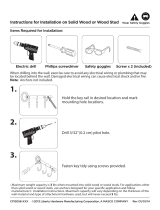
Tools NeededEN
Herramientas necesariasES
Outils requisFR
Not included
No se incluye
Non inclus
CONTENTS
TOOLS NEEDED
Wall Kit - POWER 55
DescriptionQtyPart #Pouch #
Wall Phillips Hex Screw M6 x 50mm6W-AW-A
Wall Anchors M66W-BW-B
Wood Drill Bit 1/8"1W-CW-C
Bubble Level1W-DW-D
Philips screws M5 X 12 mm (Locking Screws)2M-OM-O
Wire Holders (Zip Ties)3M-NM-N
Circular Spacers: 19.5mm OD x 8.25mm ID x 14.5mm H4M-MM-M
Square Washers4M-LM-L
Washer OD 10mm ID 5mm x 1.0mm4M-KM-K
Philips screws M8 x 45mm4M-JM-J
Philips screws M8 x 29mm4M-IM-I
Philips screws M8 x 15mm4M-HM-H
Philips screws M6 x 45mm4
M-GM-G
Philips screws M6 X 20mm4
M-FM-F
Philips screws M6 x 15mm
4
M-EM-E
Philips screws M5 x 45mm4M-DM-D
Philips screws M5 x 15mm4M-CM-C
Philips screws M4 x 45mm
4M-BM-B
Philips screws M4 x 15mm
4M-AM-A
DescriptionQtyPart #Pouch #
Monitor Kit - POWER 55
M-C
M-O

P7
Percer
Agujerear
Drill
EN
ES
FR
Clé hexagonale
Llave Allen
Allen Wrench
EN
ES
FR
SYMBOL KEY
Level
EN
Nivel
ES
Niveau
FR
Attention
Precaución
Caution
EN
ES
FR
Marque de crayon
Marque con lápiz
Pencil Mark
EN
ES
FR
Marteau
Martillo
Hammer
EN
ES
FR
Optionnel
Opcional
Optional
EN
ES
FR
Tournevis Phillips
Destornillador Phillips
Phillips Screwdriver
EN
ES
FR
Retirez
Retire
Remove
EN
ES
FR
Ajustez
Ajuste
Adjust
EN
ES
FR
Gestion des câbles
Sistema de organización de cables
Cable Management
EN
ES
FR
Serrer avec les doigts
Ajuste manual
Hand tighten
EN
ES
FR
Tighten Fastener
EN
Ajuste el sujetador
ES
Serrez l'attache
FR
Loosen Fastener
EN
Afloje el sujetador
ES
Desserrez l'attache
FR
Repérez la position centrale
Encuentre la posición del centro
Find Center Position
EN
ES
FR

P8
W
OOD STUD INSTALLATION
EN Find stud(s) and mark edge and center locations.
ES Ubique el panel y marque las ubicaciones de los bordes y el centro.
FR
Repérez l'emplacement d'une poutre, puis marquez l'emplacement des bords et du
centre de cette poutre.
STUD
STUD
STEP 2
STEP 1
Stud # 2
Stud # 1
Adjust wall template (2) to accommodate width of studs. Refer to Wall Template (2) for further instructions.
Stud #1 must be positioned in Section (A)
Stud #2 must be positioned in Section
(
B
-
Ri
g
ht
)
.
B
Right
A
CAUTION: Any Wood Stud Installation Greater than 16” Wide Must use a Dry
Wall Anchor (Not Included) in the (B-Left) Section of the Wall Template.
B
Left
2

P9
WOOD STUD INSTALLATION
Good No Good
Utilisez le gabarit mural pour marquer les emplacements de montage
Use la guía de la pared para marcar el lugar donde se realizará la instalación
Use wall template to mark mounting locationsEN
ES
FR
STEP 5
Follow directions on the mounting template and use Bubble Level (W-D),
secure to wall. Locate the middle mark of the Wall Template, use a
Pin (not included) to secure the template into place.
STEP 3 STEP 4
W-D
2
2
2

P11
MASONRY INSTALLATION
Place Wall Template (2) on solid concrete wall. A total of 6 Wall Anchors (W-B)
and 6 Wall Screws (W-A) must be installed. Refer to Wall Template (2) for further
instructions.
Two Wall Anchors (W-B), Screws (W-A) must be installed in Section (A).
Two Wall Anchors (W-B), Screws (W-A) must be installed in Section (B Left).
Two Wall Anchors (W-B), Screws (W-A) must be installed in Section (B Right).
Solid Concrete Only
Do Not Drill Into Mortar
Solid Concrete Only
Do Not Drill Into Mortar
B
Right
A
B
Left
2

P12
MASONRY INSTALLATION
Good No Good
Utilisez le gabarit mural pour marquer les emplacements de montage
Use la guía de la pared para marcar el lugar donde se realizará la instalación
Use wall template to mark mounting locationsEN
ES
FR
Follow directions on the mounting template and use Bubble Level (W-D),
secure to wall. Locate the middle mark of the Wall Template.
STEP 1 STEP 2
For solid concrete wall installation 6 screws and anchors are required.
STEP 3
2
2 W-D
2

P13
MASONRY INSTALLATION
Masonry Pilot
Pilot Hole Size Pilot Drill Length
5/16 inch 2 – 1/8” inch
8 mm 55 mm
Drill pilot hole
Realice el agujero guía
Percez le trou de guidageInstallation sur mur en béton
Instalación en pared de hormigón
Concrete Wall Installation
EN
ES
FR
Solid Concrete
Concreto sólido
Béton massif
Solid Concrete Only
Do Not Drill Into Mortar
Masonry mounting must use a minimum of 6 lag screws and anchors
STEP 4
STEP 5
Solid Concrete Only
Do Not Drill Into Mortar
W-B
Not Included

P14
MASONRY INSTALLATION
Before lifting mount into position ensure that all pilot holes are drilled and
Anchors (W-B) necessary are installed. Assistance may be needed to hold
mount in position while installing screws. NOTE: 6 wall screws and anchors
are required in solid concrete wall installation.
HAND TIGHTEN ONLY!
Failure to do this may result / damage of stripping the Anchors.
Tighten FastenersEN
Ajuste el sujetador
ES
Serrez l'attache
FR
X 6
X 6
STEP 6
Hand tools only
Herramientas de mano solamente
Outils manuels uniquement
5
1
5
W-A
W-A
VESA Install – Continue… Non VESA – Go To Page 22

P15
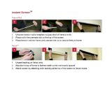
READ!!! SLIM TV (6 cm thickness or less only)
Remove perforated tabs to Access Tension Springs (11) on Front Monitor Plate. Remove
the first screw to the right side of the Monitor Plate.
Insert screwdriver or solid rod into slot holes on Right, applying pressure (IMPORTANT!).
Assistance Highly Recommended: While applying pressure carefully unscrew second
screw.
Once second screw is removed, slowly allow the tension spring to unwind upwards. Allow it
uncoil until it rests. If in future a larger Monitor / TV are to be installed on Auto Wall Mount,
Please Reverse Steps Above to adjust Tension to Springs.
READ!!!!! Mount comes adjusted factory default suitable to fit most TV’s.
This step is ONLY Slim Size Televisions with a depth of 0.24 in. (6 cm) or
less. Check you TV installation Manual if your TV fits this criteria. You must
adjust TV’s in this size range in order for the mount to function properly. If your
TV does not fit this criteria, Skip to Page 16.
10
11
11
SPRING TENSION IS HIGH. DO NOT LOOSE GRIP ON SCREWDRIVER / ROD!

P16
VESA MONITOR INSTALLATION
100mm
100mm
200mm
200mm
200mm
200mm
200mm
200mm x 200mm
100mm x 200 mm
VESA

P17
VESA MONITOR INSTALLATION
Dévisser à moitié
Afloje un poco
Loosen Half WayEN
ES
FR
Dévisser à moitié
Afloje un poco
Loosen Half WayEN
ES
FR
X 2
X 2
Loosen Horizontal Rail Screws (12).
Punch out perforated lines to access horizontal rail screws (12).
12
12
10
10
1
10
12

P18
VESA MONITOR INSTALLATION
Retirez
Retire
RemoveEN
ES
FR
Loosen FastenerEN
Afloje el sujetador
ES
Desserrez l'attache
FR
Remove the End Caps (6) from Horizontal Rails (5). The End Cap
Sticker must be peeled back to access the screws. Discard End Cap
Stickers.
5
5
6
5
6
6
5
1

P19
VESA MONITOR INSTALLATION
Retirez
Retire
RemoveEN
ES
FR
Retirez
Retire
RemoveEN
ES
FR
5
5
5
1
1

P20
VESA MONITOR INSTALLATION
EN Use spacers for recessed mounting holes or to access A/V inputs
ES Use los espaciadores para agujeros de montaje empotrados o para acceder a las entradas de A/V
FR Utilisez les entretoises sur les trous de montage encastrés ou pour accéder aux entrées A/V
EN
Attention: If screw "bottoms out" use washers (not included) to take up slack
ES Atención: Si el tornillo hace tope, utilice arandelas (no se incluyen) para ajustarlo al máximo.
FR Attention : Si les vis dépassent en dessous, utilisez des rondelles (non incluses) pour compenser
CAUTION
**NOTE**
WHEN INSTALLING FLAT PANEL TV DO NOT OVER TIGHTEN SCREWS AND
MAKE SURE THAT SCREWS DO NOT BOTTOM OUT IN MOUNTING HOLES!
!
M-M
M-A ~ M-K
Hand Tighten Only!

P21
VESA MONITOR INSTALLATION
Installez partiellement
Instalación parcial
Partially installEN
ES
FR
Partially install top two Philips screws (M-A ~ M-J). Please use Washers
(M-K) for screw sizes M4 and M5 (M-A ~ MD).
Do Not Tighten
Installer le moniteur avec les fixations de moniteur, M-A, M-B, etc…
Coloque la pantalla utilizando los materiales de instalación de la pantalla, M-A, M-B, etc…
Attach monitor using monitor hardware, M-A, M-B, etc…EN
ES
FR
M-A ~ M-K
M-K
M-A M-F
M-I M-J
M-D M-E M-G
M-H
M-B
M-C
/