24-8-2010 3 IR Link Pro
User Guide
CONTENTS
1. Conformity of Use
2. Introduction
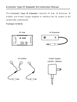
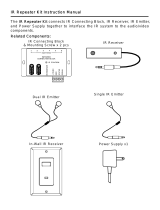
3. Kit content
4. How does the ebode IR Link Pro work?
5. Installing the ebode IR Link Pro
6. Operation
7. How to avoid and solve possible problems
8. Technical information
1. Conformity of Use
For carefree and safe use of this product, please read this manual and safety information
carefully and follow the instructions. The unit is registered as a device that does not cause or
suffer from radio-frequency interference. It is CE approved and it conforms with the Low
Voltage Directory. The safety and installation instructions must be observed. Technical
manipulation of the product or any changes to the product are forbidden, due to security and
approval issues. Please take care to set up the device correctly - consult your user guide. Young
children should use the device only under adult supervision. No guarantee or liability will be
accepted for any damage caused due to incorrect use of the equipment supplied, other than
indicated in this owner’s manual.
SAFETY WARNINGS
• To prevent short circuits, this product (except if specified for outdoor usage) should only be
used inside and only in dry spaces. Do not expose the components to rain or humidity.
• Avoid strong mechanical tear and wear, extreme ambient temperatures, strong vibrations
and atmospheric humidity.
• Do not disassemble any part of the product: no user-serviceable parts are inside. The
product should only be repaired or serviced by qualified and authorized service personnel.
Defected pieces must be replaced by original (spare) parts.
• Batteries: keep batteries out of the reach of children. Dispose of batteries as chemical waste.
Never use old and new batteries or different types of batteries together. Remove the
batteries when you are not using the system for a longer period of time. When inserting
batteries be sure the polarity is respected. Make sure that the batteries are not short
circuited and are not disposed in fire (danger of explosion).
In case of improper usage or if you have opened, altered and repaired the product yourself, all
guarantees expire. The supplier does not accept responsibility in the case of improper usage of
the product or when the product is used for purposes other than specified. The supplier does not
accept responsibility for additional damage other than covered by the legal product
responsibility.
2. Introduction
Congratulations on purchasing the ebode IR Link Pro. Our ebode proprietary eIR
2
x
TM
(pronounce
Irex) Technology guarantees a high level of immunity for InfraRed noise from direct sunlight, CFL
lighting and Flat Panel TV’s (including Plasma, LCD and LED). This kit contains one 3IREDB for
control of 3 devices, and a 1IRQC Quick Connect cable for direct control of popular
audio/video Receivers (e.g. Yamaha, Onkyo, Denon, Marantz, NAD, Harman Kardon etc). The
IR Link Pro runs on a 12VDC mains adapter (included) and is expandable with extra IR
Link Receivers in different rooms.