Page is loading ...

126821-1
10/98
Printed on
recycled paper.
© 1998 by Crown International, Inc., P.O. Box 1000, Elkhart, Indiana
46515-1000 U.S.A. Telephone: 219-294-8000. The
IQ–P.I.P.–SMT
is
produced by the Professional Audio Division of Crown International,
Inc. Trademark Notice:
MPX-6
™
,
SMX-6
™
,
SmartAmp
™
and
Macro
Reference
™
are trademarks and
Amcron
®
,
Crown
®
,
IQ System
®
,
IOC
®
,
ODEP
®
,
Macro-Tech
®
,
Com-Tech
®
and
P.I.P.
®
are registered
trademarks of Crown International, Inc. Other trademarks are the
property of their respective owners.
An IQ System
®
Programmable Input Processor
for Crown
®
P.I.P.
®
-compatible Power Amplifiers

Page 2
IQ P.I.P.–SMT
NORTH AMERICA
SUMMARY OF WARRANTY
The Crown Audio Division of Crown International, Inc., 1718 West Mishawaka Road,
Elkhart, Indiana 46517-4095 U.S.A. warrants to you, the ORIGINAL PURCHASER and
ANY SUBSEQUENT OWNER of each NEW Crown product, for a period of three (3)
years from the date of purchase by the original purchaser (the “warranty period”) that
the new Crown product is free of defects in materials and workmanship. We further
warrant the new Crown product regardless of the reason for failure, except as excluded
in this Warranty.
ITEMS EXCLUDED FROM THIS CROWN WARRANTY
This Crown Warranty is in effect only for failure of a new Crown product which occurred
within the Warranty Period. It does not cover any product which has been damaged
because of any intentional misuse, accident, negligence, or loss which is covered
under any of your insurance contracts. This Crown Warranty also does not extend to the
new Crown product if the serial number has been defaced, altered, or removed.
WHAT THE WARRANTOR WILL DO
We will remedy any defect, regardless of the reason for failure (except as excluded),
by repair, replacement, or refund. We may not elect refund unless you agree, or unless
we are unable to provide replacement, and repair is not practical or cannot be timely
made. If a refund is elected, then you must make the defective or malfunctioning
product available to us free and clear of all liens or other encumbrances. The refund
will be equal to the actual purchase price, not including interest, insurance, closing
costs, and other finance charges less a reasonable depreciation on the product from
the date of original purchase. Warranty work can only be performed at our authorized
service centers or at the factory. We will remedy the defect and ship the product from
the service center or our factory within a reasonable time after receipt of the defective
product at our authorized service center or our factory. All expenses in remedying the
defect, including surface shipping costs in the United States, will be borne by us. (You
must bear the expense of shipping the product between any foreign country and the
port of entry in the United States and all taxes, duties, and other customs fees for such
foreign shipments.)
HOW TO OBTAIN WARRANTY SERVICE
You must notify us of your need for warranty service not later than ninety (90) days after
expiration of the warranty period. All components must be shipped in a factory pack,
which, if needed, may be obtained from us free of charge. Corrective action will be
taken within a reasonable time of the date of receipt of the defective product by us or
our authorized service center. If the repairs made by us or our authorized service center
are not satisfactory, notify us or our authorized service center immediately.
DISCLAIMER OF CONSEQUENTIAL & INCIDENTAL DAMAGES
YOU ARE NOT ENTITLED TO RECOVER FROM US ANY INCIDENTAL DAMAGES
RESULTING FROM ANY DEFECT IN THE NEW CROWN PRODUCT. THIS INCLUDES
ANY DAMAGE TO ANOTHER PRODUCT OR PRODUCTS RESULTING FROM SUCH
A DEFECT.
SOME STSOME ST
SOME STSOME ST
SOME ST
AA
AA
A
TES DO NOT ALLOW THE EXCLUSION OR LIMITTES DO NOT ALLOW THE EXCLUSION OR LIMIT
TES DO NOT ALLOW THE EXCLUSION OR LIMITTES DO NOT ALLOW THE EXCLUSION OR LIMIT
TES DO NOT ALLOW THE EXCLUSION OR LIMIT
AA
AA
A
TIONS OFTIONS OF
TIONS OFTIONS OF
TIONS OF
INCIDENTINCIDENT
INCIDENTINCIDENT
INCIDENT
AL OR CONSEQUENTIAL DAMAGES, SO THE ABOVE LIMITAL OR CONSEQUENTIAL DAMAGES, SO THE ABOVE LIMIT
AL OR CONSEQUENTIAL DAMAGES, SO THE ABOVE LIMITAL OR CONSEQUENTIAL DAMAGES, SO THE ABOVE LIMIT
AL OR CONSEQUENTIAL DAMAGES, SO THE ABOVE LIMIT
AA
AA
A
TION ORTION OR
TION ORTION OR
TION OR
EXCLUSION MAEXCLUSION MA
EXCLUSION MAEXCLUSION MA
EXCLUSION MA
Y NOT APPLY NOT APPL
Y NOT APPLY NOT APPL
Y NOT APPL
Y TO YOU.Y TO YOU.
Y TO YOU.Y TO YOU.
Y TO YOU.
WARRANTY ALTERATIONS
No person has the authority to enlarge, amend, or modify this Crown Warranty. This
Crown Warranty is not extended by the length of time which you are deprived of the use
of the new Crown product. Repairs and replacement parts provided under the terms
of this Crown Warranty shall carry only the unexpired portion of this Crown Warranty.
DESIGN CHANGES
We reserve the right to change the design of any product from time to time without notice
and with no obligation to make corresponding changes in products previously
manufactured.
LEGAL REMEDIES OF PURCHASER
THIS CROWN WARRANTY GIVES YOU SPECIFIC LEGAL RIGHTS, YOU MAY ALSO
HAVE OTHER RIGHTS WHICH VARY FROM STATE TO STATE. No action to enforce this
Crown Warranty shall be commenced later than ninety (90) days after expiration of the
warranty period.
THIS STATEMENT OF WARRANTY SUPERSEDES ANY OTHERS
CONTAINED IN THIS MANUAL FOR CROWN PRODUCTS.
9/90
YEAR
3
THREE YEAR
FULL WARRANTY

Page 3
IQ P.I.P.–SMT
WORLDWIDE
SUMMARY OF WARRANTY
The Crown Audio Division of Crown International, Inc., 1718 West Mishawaka Road,
Elkhart, Indiana 46517-4095 U.S.A. warrants to you, the ORIGINAL PURCHASER and
ANY SUBSEQUENT OWNER of each NEW Crown
1
product, for a period of three (3)
years from the date of purchase by the original purchaser (the “warranty period”) that
the new Crown product is free of defects in materials and workmanship, and we further
warrant the new Crown product regardless of the reason for failure, except as excluded
in this Crown Warranty.
1
Note: If your unit bears the name “Amcron,” please substitute it for the name “Crown”
in this warranty.
ITEMS EXCLUDED FROM THIS CROWN WARRANTY
This Crown Warranty is in effect only for failure of a new Crown product which occurred
within the Warranty Period. It does not cover any product which has been damaged
because of any intentional misuse, accident, negligence, or loss which is covered
under any of your insurance contracts. This Crown Warranty also does not extend to the
new Crown product if the serial number has been defaced, altered, or removed.
WHAT THE WARRANTOR WILL DO
We will remedy any defect, regardless of the reason for failure (except as excluded),
by repair, replacement, or refund. We may not elect refund unless you agree, or unless
we are unable to provide replacement, and repair is not practical or cannot be timely
made. If a refund is elected, then you must make the defective or malfunctioning
product available to us free and clear of all liens or other encumbrances. The refund
will be equal to the actual purchase price, not including interest, insurance, closing
costs, and other finance charges less a reasonable depreciation on the product from
the date of original purchase. Warranty work can only be performed at our authorized
service centers. We will remedy the defect and ship the product from the service center
within a reasonable time after receipt of the defective product at our authorized service
center.
HOW TO OBTAIN WARRANTY SERVICE
You must notify us of your need for warranty service not later than ninety (90) days after
expiration of the warranty period. All components must be shipped in a factory pack.
Corrective action will be taken within a reasonable time of the date of receipt of the
defective product by our authorized service center. If the repairs made by our
authorized service center are not satisfactory, notify our authorized service center
immediately.
DISCLAIMER OF CONSEQUENTIAL & INCIDENTAL DAMAGES
YOU ARE NOT ENTITLED TO RECOVER FROM US ANY INCIDENTAL DAMAGES
RESULTING FROM ANY DEFECT IN THE NEW CROWN PRODUCT. THIS INCLUDES
ANY DAMAGE TO ANOTHER PRODUCT OR PRODUCTS RESULTING FROM SUCH
A DEFECT.
WARRANTY ALTERATIONS
No person has the authority to enlarge, amend, or modify this Crown Warranty. This
Crown Warranty is not extended by the length of time which you are deprived of the use
of the new Crown product. Repairs and replacement parts provided under the terms
of this Crown Warranty shall carry only the unexpired portion of this Crown Warranty.
DESIGN CHANGES
We reserve the right to change the design of any product from time to time without notice
and with no obligation to make corresponding changes in products previously
manufactured.
LEGAL REMEDIES OF PURCHASER
No action to enforce this Crown Warranty shall be commenced later than ninety (90)
days after expiration of the warranty period.
THIS STATEMENT OF WARRANTY SUPERSEDES ANY OTHERS
CONTAINED IN THIS MANUAL FOR CROWN PRODUCTS.
9/90
THREE YEAR
FULL WARRANTY
YEAR
3

Page 4
IQ P.I.P.–SMT
Quick Install Procedure
This procedure is provided for those who are already familiar with Crown’s
IQ System
and who would like to install the
IQ–P.I.P.–SMT
in the shortest time possible. Less
experienced installers or those wishing a full explanation of the installation procedure
are encouraged to go to Section 4 where the full installation procedure is described.
Prepare the IQ–P.I.P.–SMT:
1. Set the IQ address switch SW1 (see Figures 4.1 and 4.2) on the
IQ–P.I.P.–
SMT
to an unused IQ address. (Tip: Record the IQ address on the small
blank label that is provided on lower right corner of the
P.I.P.
panel.)
2. Set the input switches S1 and S2 (see Figures 4.3 and 4.4) for the desired
input gain and, if a microphone input is desired, phantom power. (Tip:
Record the input setting on the small blank label that is provided on lower
right corner of the
P.I.P.
panel.)
3. Set jumpers JP4 and JP5. Set both jumper JP4 and JP5 to the “OUT” posi-
tion if either a
PIP2
-compatible amplifier (such as the CT-10 Series or
Macro-
Tech 5000VZ)
will be used (Figure 2.1 and 4.9). Both JP4 and JP5 should be
set to the “IN” position for all other amplifiers.
Prepare the amplifier:
5. Turn down the level controls of the amplifier and turn off the amplifier.
6. Unplug the power cord of the amplifier from the AC mains.
7. Remove the existing
P.I.P.
or cover panel from the amplifier back panel (two
screws).
8. Set the amplifier input sensitivity switch to 0.775 V. (See the
Reference
or
Owner’s Manual
of the amplifier.)
Install the IQ–P.I.P.–SMT into the amplifier:
9. Carefully ground yourself to the chassis of the amplifier before installing the
IQ–P.I.P.–SMT
. It is a good idea to maintain ground contact between yourself
and the amplifier while inserting the module into the
P.I.P.
card rails in the
next step.
10. Install the
IQ–P.I.P.–SMT
into the amplifier:
Standard P.I.P. Amplifiers:
Align the edges of the
IQ–P.I.P.–SMT
in the
P.I.P.
card rails and firmly push the unit in until it is seated against the mounting
bracket (Figure 4.6).
PIP2 Compatible Amplifiers:
Connect the
PIP2
input adapter to the amplifier
input cables. Plug the
IQ–P.I.P.–SMT
into the
PIP2
input adapter and insert
the assembly into the
P.I.P.
opening in the back of the amplifier (Figure 4.7
and 4.8).
11. Tighten the two
P.I.P.
mounting screws until it is secured to the amplifier
back panel.
Install the wiring:
12. Connect the
IQ–P.I.P.–SMT
to the
IQ System
via the Crown Bus (see Section
4.6 if more information is needed).
13. Connect the audio signal wiring to the
IQ–P.I.P.–SMT
(see Section 4.7 if more
information is needed).
14. Connect the amplifier back to the AC receptacle.
Adjust the levels and scale factors:
15. Turn the level controls of the amplifier to their full setting. Use the software-
controlled input attenuators on the
IQ–P.I.P.–SMT
to adjust the input levels
down.
16.
Standard P.I.P. Amplifiers:
Manually configure the scaling factors of the
IQ–
P.I.P.–SMT
with appropriate
IQ System
software.
PIP2 Compatible Amplifiers:
The scaling factors will be automatically set.

Page 5
IQ P.I.P.–SMT
The information furnished in this manual does not include all of the details
of design, production, or variations of the equipment. Nor does it cover
every possible situation which may arise during installation, operation or
maintenance. If you need special assistance beyond the scope of this
manual, please contact our Technical Support Group.
Crown Audio Division Technical Support Group
Plant 2 SW, 1718 W. Mishawaka Rd., Elkhart, Indiana 46517 U.S.A.
Phone: 800-342-6939 (North America, Puerto Rico and Virgin Islands)
or 219-294-8200
Fax: 219-294-8301 Fax Back: 800-294-4094 (North America only) or
219-293-9200
Internet: http://www.crownaudio.com
WARNING
TO REDUCE THE RISK OF ELECTRIC
SHOCK, DO NOT EXPOSE THIS
EQUIPMENT TO RAIN OR MOISTURE!
FCC COMPLIANCE NOTICE
This equipment has been tested and found to comply
with the limits for a Class A digital Device, pursuant to
Part 15 of the FCC Rules. These limits are designed
to provide reasonable protection against harmful
interference when the equipment is operated in a
commercial environment. This equipment generates,
uses and can radiate radio frequency energy and, if
not installed and used in accordance with the
instruction manual, may cause harmful interference
to radio communications. Operation of this
equipment in a residential area is likely to cause
harmful interference in which case the user will be
required to correct the interference at his own
expense.
“The user is cautioned that any changes or
modifications not expressly approved by Crown
International could void the user’s authority to operate
the equipment.”

Page 6
IQ P.I.P.–SMT
CONTENTS
Quick Install Procedure ......................................................... 3
1 Welcome................................................................................. 8
1.1 Unpacking ................................................................... 8
2 Facilities ................................................................................. 9
3 Features ............................................................................... 12
3.1 Amplifier Information .................................................. 12
3.2 Amp Mode ................................................................. 12
3.3 Power Control ............................................................ 12
3.4 Input Signal Level Monitor.......................................... 12
3.5 Signal Mute................................................................ 12
3.6 Polarity Inverter .......................................................... 12
3.7 Input Signal Attenuator .............................................. 12
3.8 Input Signal Compressor/Limiter ................................ 13
3.9 Output Signal Level Monitor ....................................... 13
3.10 Smooth/Output Signal Limiter .................................... 13
3.11
IOC
Event Monitor...................................................... 14
3.12 Prolonged
IOC
Warning ............................................. 14
3.13
ODEP
Level Monitor................................................... 14
3.14
ODEP
Conservation ................................................... 14
3.15 Excessive
ODEP
Warning .......................................... 15
3.16 Fault Warning............................................................. 15
3.17 Auto Standby ............................................................. 16
3.18 Auto ........................................................................... 16
3.19 Crown Bus “Drop Out” Relays ................................... 16
3.20 DSPI .......................................................................... 16
3.21 AUX Output ............................................................... 17
3.22 Memory Backup ........................................................ 17
3.23 Reset ......................................................................... 17
3.24 User Default Settings ................................................. 17
4 Installation ........................................................................... 18
4.1 Prepare the
IQ–P.I.P.–SMT
.......................................... 18
4.2 Prepare the Amplifier ................................................. 21
4.3 Install the
IQ–P.I.P.–SMT
into the Amplifier .................. 21
4.4 Install the Wiring ........................................................ 22
4.5 Adjust the Levels & Scale Factors.............................. 22
4.6 A Closer Look at Crown Bus Wiring ........................... 23
4.7 A Closer Look at Audio Signal Wiring......................... 26
4.8 Using the AUX Connector.......................................... 27
4.8.1 AUX Output.................................................... 27

Page 7
IQ P.I.P.–SMT
4.8.2 AUX Input....................................................... 27
5 Technical Information.......................................................... 29
5.1 Audio Signals............................................................. 29
5.2 Amplifier Monitoring: “Monitor Inputs” ........................ 29
5.3 Amplifier Control ........................................................ 29
5.4
IQ System
Communications....................................... 30
5.5 Microprocessor and Reset Switch ............................. 30
6 Specifications ...................................................................... 32
7 IQ Address Tables ................................................................ 34
8 Service ................................................................................. 37
8.1 Worldwide Service ..................................................... 37
8.2 North American Service ............................................. 37
8.2.1 Service at a N. Am. Service Center ................ 37
8.2.2 Factory Service .............................................. 37
Contents continued...
ILLUSTRATIONS
1.1
IQ–P.I.P.–SMT ...............................................................................
8
2.1 The
IQ–P.I.P.–SMT
Facilities.......................................................... 9
4.1 IQ Address Switch (SW1) Location ............................................. 18
4.2 IQ Address Switch (SW1) Values................................................ 19
4.3 Input Switch (S1, S2) Location .................................................... 20
4.4 Input Switch (S1, S2) Settings .................................................... 20
4.5 Installation into a Standard
P.I.P.
Amplifier.................................. 21
4.6
PIP2
Input Adapter Connection .................................................. 22
4.7 Installation into a
PIP2
Amplifier .................................................. 22
4.8 Amplifier Scale Factor Values and Output Signal Pad Settings... 23
4.9
IQ–P.I.P.–SMT
Output to IQ Component with DIN ....................... 25
4.10
IQ–P.I.P.–SMT
Output to IQ Component w/ Screw Term. Plug .... 25
4.11 IQ Component w/ Screw Term. Plug to
IQ–P.I.P.–SMT
Input....... 25
4.12 Crown Bus Wiring “Loops” from Output to Input ......................... 26
4.13 Audio Input Wiring ...................................................................... 26
4.14 The Internal AUX Circuit ............................................................. 28
4.15 A Sample AUX Output Circuit ..................................................... 28
5.1
IQ–P.I.P.–SMT
Circuit Block Diagram .......................................... 31
7.1 IQ Address Switch (SW1) Settings from 0 to 83 .......................... 34
7.2 IQ Address Switch (SW1) Settings from 84 to 167 ...................... 35
7.3 IQ Address Switch (SW1) Settings from 168 to 250 .................... 36

Page 8
IQ P.I.P.–SMT
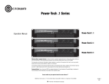
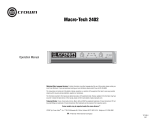
Fig. 1.1 IQ–P.I.P.–SMT
1 Welcome
The
IQ–P.I.P.–SMT
is a
PIP2
input
module for Crown
P.I.P.
®
(program-
mable input processor) and
PIP2
-
compatible amplifiers. Because it is
also an
IQ2
-series component, it sup-
ports Crown’s UCODE protocol and
requires an
IQ System
®
with an
IQ2
-
compatible IQ interface. UCODE
(universal code) enables users and
third parties to develop custom soft-
ware objects to control and monitor
IQ2
-compatible components like the
IQ–P.I.P.–SMT
.
The
IQ–P.I.P.–SMT
connects the am-
plifier to the Crown Bus of an
IQ Sys-
tem
so the amplifier can be controlled
and monitored. With its
SmartAmp
™
features, it offers several automation
functions such as the ability to auto-
matically turn on an amplifier chan-
nel (high voltage supply) when it is
needed and then turn it back off
when it is no longer needed. This
conserves power and saves money.
This manual will help you success-
fully install your unit. We strongly rec-
ommend that you read all the
instructions, warnings and cautions
contained within. Also for your pro-
tection, please send in the warranty
registration card today and save the
bill of sale since it is your official proof
of purchase.
1.1 Unpacking
The unit is shipped in a protective
antistatic bag.
CAUTION: STATIC ELECTRICITY
MAY DAMAGE THE UNIT. Use cau-
tion when handling the unit. Carefully
ground yourself BEFORE touching
the unit. For added safety, touch the
outer metal collar of either Crown Bus
connector. Avoid unnecessarily
touching the components, edge con-
nector or solder pads on the circuit
boards.
Please unpack and inspect the unit
for any damage that may have oc-
curred during transit. If damage is
found, notify the transportation com-
pany immediately. Only you, the con-
signee, may initiate a claim with the
carrier for shipping damage. Crown
will be happy to cooperate fully as
needed. Save the shipping carton as
evidence of damage for the shipper’s
inspection.
Even if the unit arrived in perfect con-
dition, as most do, save all packing
materials. NEVER SHIP THE UNIT
WITHOUT THE FACTORY PACK.

Page 9
IQ P.I.P.–SMT
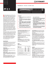
2 Facilities
A. Mounting Screws
The
IQ–P.I.P.–SMT
is secured to the
back panel of the amplifier with two
phillips-head screws and star-tooth
lock washers. The lock washers are
required for proper ground connec-
tion.
B. Balanced Audio Inputs
A 3-pin female XLR connector is pro-
vided for balanced audio input to
each channel of the amplifier. Pin 1 is
chassis (gnd); pin 2 is not inverted
(+); and pin 3 is inverted (–).
Do not
use the Ch.2 input if the amplifier is
configured in either Bridge or Paral-
lel-Mono mode.
Front View
Bottom View
Fig. 2.1 The IQ–P.I.P.–SMT Facilities

Page 10
IQ P.I.P.–SMT
C. Reset Switch
A multifunction reset switch is pro-
vided to restore the
IQ–P.I.P.–SMT
to
a prior state. It can be depressed
with a straightened paper clip
through the small hole in the
P.I.P.
panel. Press the reset switch for less
than 2 seconds and all settings, ex-
cept the amplifier model scale fac-
tors, will be reset with “user default”
parameters and the DSPI will flash
once. (If no “user default” settings
have been stored, the unit will be re-
set to the “factory default” settings
described next.) Press the reset
switch for more than 2 seconds and
the same settings will be reset with
“factory default” parameters and the
DSPI will flash twice. After the unit
has been reset to the factory default
settings, it will behave like a standard
P.I.P.-FX
until it is reprogrammed by
an
IQ System
or it is toggled to the
“user default” settings.
D. AUX Connector
A 3-pin male mini XLR connector is
provided to control auxiliary equip-
ment. When the AUX feature is turned
on, +15 VDC is provided across pin
1 (gnd) and pin 3 (+). A nominal cur-
rent of 10 mA is available. The AUX
connector also includes a high-im-
pedance input that can sense logic
signals.
E. DSPI
The DSPI is a Data Signal Presence
Indicator which flashes whenever a
valid IQ command has been re-
ceived. The indicator can also be
forced to stay on to aid rapid trouble-
shooting of the Crown Bus wiring.
F. Crown Bus Input Connector
A lockable 5-pin female DIN connec-
tor is provided for input connection to
the Crown Bus. A mating Switchcraft
502 series connector can be ordered
from Crown (part C 7776-5). Pin 1 is
negative (–), pin 2 is positive (+), and
pin 3 is ground (gnd). Pins 4 and 5
are not used.
G. Crown Bus Output Connector
A lockable 4-pin female DIN connec-
tor is used for output connection to
the Crown Bus. A mating Switchcraft
502 series connector can be ordered
from Crown (part C 7777-3). Pin 1 is
negative (–) and pin 2 is positive (+).
Pins 3 and 4 are not used.
H. Input Switches (S1, S2)
An 8-section DIP switch is used to
configure each input. These switches
are located on the bottom circuit
board. S1 configures the input of
Channel 1 and S2 configures the in-
put of Channel 2. The switches acti-
vate a microphone preamp and
enable phantom power. The preamp
can be turned off (0 dB gain) or set to
either 20 or 40 dB of gain. See Sec-
tion 4.1.
I.
P.I.P.
Edge Connector
The gold-plated edge connector of
the top IQ circuit board inserts into
the
P.I.P.
connector inside the back of
the amplifier. Use care when install-
ing a
P.I.P.
module to be certain that
the edge connector is properly in-
serted into the amplifier’s
P.I.P.
con-
nector.
J. Amplifier Output Pad
Jumpers (JP4, JP5)
These jumpers enable the circuitry
that pads the output signal feeding
the
IQ–P.I.P.–SMT
so it can be prop-
erly scaled. They should be set to the
“IN” position as marked on the digital

Page 11
IQ P.I.P.–SMT
circuit board for MA-600 - 3600VZ
and SR I & II. Use the “OUT” position
whenever the unit is installed into a
PIP2
-compatible. (CT "10" Series or
MA 5000VZ)
K.
PIP2
SIP Sockets (RN1, RN2)
These eight-pin SIP (single in-line
package) sockets are provided for
full
PIP2
compatibility.
IQ-P.I.P.-SMT-
PIP2
modules (required for PIP2-
compatible amplifiers) should come
with the SIP networks already in-
stalled. The SIP networks are not re-
quired and should be absent on
standard
IQ-P.I.P.-SMT
modules.
L. IQ Circuit Board (Top)
The top circuit board contains the IQ
communication circuitry, including
the IQ address switch (SW1), ampli-
fier output pad jumpers (JP4, JP5),
PIP2
SIP sockets (RN1, RN2) and the
P.I.P.
edge connector.
M. Audio Circuit Board
(Bottom)
The bottom circuit board contains the
audio analog circuitry, including the
input switches (S1, S2).
N. IQ Address Switch (SW1)
An 8-section DIP (dual in-line pack-
age) switch is used to set the IQ ad-
dress of the unit (see Section 4.1).
This switch is located on the top cir-
cuit board. Each IQ component on a
Crown Bus is given a unique IQ ad-
dress so it can be independently
controlled and monitored. Two or
more IQ components of the same
type should NEVER have the same
address on the same Crown Bus
loop.

Page 12
IQ P.I.P.–SMT
3 Features
With an
IQ–P.I.P.–SMT
module a
Crown amplifier can be monitored
and controlled by an
IQ System
. And
the module has
SmartAmp
™
features
which enable the amplifier to function
automatically. For example, an
IQ–
P.I.P.–SMT
can automatically turn off
the high voltage supplies of the am-
plifier when no input signal is present.
This can lower electrical usage and
provide long-term cost savings. And
it can automatically limit the audio
signal and detect and report various
problems.
Most of the features can be either
controlled or configured by a host
computer attached to the
IQ System
via an IQ interface. The host com-
puter is usually a PC and must be
running some kind of IQ software.
Please contact your Crown represen-
tative or Crown’s Technical Support
Group if you are unfamiliar with IQ
software.
3.1 Amplifier Information
(
PIP2
amplifiers only.) Several items
of information about an amplifier can
be displayed by the IQ software.
These include the manufacturer,
model, date code, serial number and
revision level. Which items are avail-
able depends on both the amplifier
and the IQ software used.
3.2 Amp Mode
The stereo/mono mode of the ampli-
fier can be stored into the unit’s
memory so the
IQ System
is aware of
the amplifier’s stereo/mono switch
setting. Storing this setting serves as
an “electronic reminder” to the sys-
tem—however, the stereo/mono
mode can
not be controlled with this
setting. The modes are Stereo (Dual),
Bridge-Mono and Parallel-Mono. This
software amp mode setting is con-
trolled by the
IQ System
.
3.3 Power Control
Each channel’s high-voltage supply
can be independently turned on and
off with the Power control. The
IQ Sys-
tem
is used to set this control.
3.4 Input Signal Level Monitor
The input signal level of each chan-
nel can be monitored by IQ software.
This monitor feature has a range from
+16 dBu to –40 dBu in ½ dB steps.
3.5 Signal Mute
The output signal of each channel
can be independently muted by the
IQ System
. The function typically pro-
vides 80 dB or more of attenuation.
3.6 Polarity Inverter
The polarity of the input signal of
each channel can be independently
inverted by the
IQ System
.
3.7 Input Signal Attenuator
An attenuator is available at the input
of each channel to control the input
signal level. These attenuators are
controlled and monitored by the
IQ
System
. They may appear to move
like “flying faders” on some IQ soft-
ware screens because they reflect all
reductions in gain that are dynami-
cally applied by the input compres-
sor/limiter, smooth/output signal
limiter and
ODEP
conservation func-
tions. Each input attenuator has a
range from 0 dB to –80 dB in ½ dB
steps. (Zero equals no attenuation.)

Page 13
IQ P.I.P.–SMT
3.8 Input Signal Compressor/
Limiter
An input signal compressor/limiter is
available for each channel. Each one
is controlled by the
IQ System
and
has five parameters:
Input Compressor: Turns this
function on/off.
Threshold: Sets the threshold,
in dB, above which the
compressor acts. The level is
measured at the input to the
P.I.P.
and corresponds to the
level shown on an input meter.
The compressor is “feed-
forward,” meaning that the level
detection point is located before
the gain control stage. The
range is from +16 dBu to –40
dBu.
Attack Time: Sets the attack
time of the compressor. The
attack time is the time it takes
the compressor to attenuate the
input signal by 10 dB. The range
is from 1 millisecond to 2
seconds.
Release Time: Sets the release
time of the compressor. The
release time is the time it takes
the compressor to increase the
input gain by 10 dB. The range
is 100 milliseconds to 30
seconds.
Ratio: Sets the compression
ratio for the compressor. The
range is 1, 2, 4, 8, 16, 32, ∞ to 1.
Note: 1:1 is the same as “off.”
3.9 Output Signal Level Monitor
The output signal level of each chan-
nel of the amplifier can be monitored
by the
IQ System
. This monitor fea-
ture has a range from –40 dB to 0 dB
where 0 dB is referenced to the rated
output voltage of the amplifier model.
(This is assumed to be 70-V or the
rated 8 ohm output for
Com-Tech
amplifiers or the rated 8 ohm output
voltage for all other amplifiers.)
The output signal of some amplifiers
must be padded before the
IQ–P.I.P.–
SMT
can scale them. This is accom-
plished by setting jumpers JP4 and
JP5 on the IQ circuit board to the “IN”
position. PIP2-compatable amplifiers
such as the MA 5000VZ and Com-
Tech "10" Series do not require these
pads. Set jumpers JP4 and JP5 to the
“OUT” position for them (see Figure
4.8).
The output signals of all amplifiers
must be scaled in order to “calibrate”
the 0 dB level. (See Section 4.5.) This
is accomplished with either an
am-am-
am-am-
am-
plifier ID codeplifier ID code
plifier ID codeplifier ID code
plifier ID code or a user
scale fac-scale fac-
scale fac-scale fac-
scale fac-
tortor
tortor
tor. The factory default setting for this
is an amplifier ID code of “CT-70V”
which assumes that the output level
is that of a
Com-Tech
amplifier (any
model) with both channels in the 70-
V output mode.
Note: PIP2-compat-
ible amplifiers are automatically
scaled by the IQ–P.I.P.–SMT.
3.10 Smooth/Output Signal
Limiter
An output signal limiter is available
for each channel. They can be used
either as “smooth” output levelers
(similar to older IQ
P.I.P.s
with
SmartAmp
features) or they can be
used as fast output limiters to protect
drivers and other system compo-
nents from large transient signals.
The output voltage of the amplifier is
limited (within 1 dB) based on real-
time sampling of the actual amplifier
output. The output limiters are con-
trolled by the
IQ System
and have
five parameters:

Page 14
IQ P.I.P.–SMT
Output Limiter: Turns this
function on/off.
Threshold
::
::
: Sets the threshold,
in dB, above which the limiter
acts. The level is based on the
scaled output voltage monitors
(see Section 3.9). The range is
from 0 dB to –40 dB.
Attack Time: Sets the attack
time of the limiter. The attack
time is defined as the time it
takes the limiter to attenuate the
input signal by 10 dB. The range
is from 10 milliseconds to 30
seconds.
Release Time: Sets the release
time of the limiter. The release
time is defined as the time it
takes the limiter to increase the
input gain by 10 dB. The range
is 100 millisecond to 30
seconds.
Ratio: The compression ratio is
fixed at ∞:1.
3.11
IOC
Event Monitor
The Input/Output Comparator
(IOC
®
)
of each channel of the amplifier can
be monitored by the
IQ System
. The
IOC
circuitry acts as a sensitive dis-
tortion meter to provide you
proof of
distortion-free performance
. If distor-
tion of any kind equals or exceeds
0.05%, the
IOC
circuit will cause an
indicator on the front of the amplifier
to flash. By monitoring these events,
the
IQ System
can flash an indicator
on the screen of the host computer to
alert a user that distortion is occur-
ring.
3.12 Prolonged
IOC
Warning
A “trigger” can be set that will cause
a warning message to appear on the
host computer’s screen if too many
IOC
events occur over a specified
length of time. Three parameters con-
trol this feature:
IOC
Error Detect: Turns this
function on/off.
IOC
Error Time: Sets the time
interval over which
IOC
events
will be counted. The range is
from 1 to 10 seconds.
IOC
Error Count: Sets the
number of
IOC
events that must
occur during the preceding time
interval before a warning
message is displayed.
Note: An
“IOC event” is one complete on-
off-on cycle.
The range is from 1
to 100 events per unit time.
3.13
ODEP
Level Monitor
The Output Device Emulation Protec-
tion
(ODEP
®
)
level of each channel of
the amplifier can be monitored by the
IQ software. This level represents the
percent of available thermodynamic
energy that is currently being used.
When the
ODEP
level reaches 100%,
the amplifier cannot produce any
more power and
“ODEP
limiting” will
begin to limit the drive level to the out-
put devices, thereby protecting them
from too much stress. (See the
amplifier’s
Reference
or
Owner’s
Manual
for more information about
ODEP
.)
3.14
ODEP
Conservation
The effects of
“ODEP
limiting” the
drive level of the output devices as
described in Section 3.13 above are
very audible. To overcome this, an
ODEP
conservation limiter is avail-
able to proportionally limit the input
audio signal as the thermodynamic
energy reserve of the amplifier is con-
sumed. This helps to prevent the am-

Page 15
IQ P.I.P.–SMT
such as a shorted speaker cable or
shorted loudspeaker. There are two
parameters which control this feature:
ODEP
Short Detect: Turns this
function on/off.
ODEP:
Sets the
ODEP
level
above which a short is
presumed to have occurred in
the load resulting in a warning
message being displayed. The
range is from 1 to 100%.
3.16 Fault Warning
Fault conditions can be monitored by
the
IQ System
and a warning mes-
sage displayed on the host
computer’s screen if they occur. If
desired, the AUX port can also be
used to signal the presence of a
“fault” condition. An amplifier “fault”
condition occurs when a channel
fails. The symptoms are a normal in-
put signal, an
IOC
condition that is
“locked” on, a high voltage supply
(VCC) that reports a normal condition
and no signal at the output of the
amplifier.
PIP2
-compatible amplifiers
monitor a “fault” signal from the am-
plifier while standard
P.I.P.
-compat-
ible amplifiers deduce a “fault”
condition from the aforementioned
symptoms. There are two parameters
which control this feature:
Fault: Turns this function on/off.
Input Drive Level: Sets the
threshold below which a fault
condition is presumed to exist in
a standard
P.I.P.
amplifier. This
parameter is necessary
because it may be normal for an
IOC
error to persist if the audio
input signal level is high.
Monitoring the input level can
help determine whether a fault
condition really exists or
plifier from “
ODEP
limiting” the drive
level of the output devices as de-
scribed earlier. In the majority of
cases, limiting the input signal pro-
duces a very smooth sound. And
since the input signal is only limited
when and to the degree necessary, it
is very difficult to detect. There are
four parameters which control this
feature:
ODEP
Conservation: Turns this
function on/off.
Trigger Level: Sets the
ODEP
level, in percent, above which
the conservation limiting will
begin. The range is from 1 to
100%.
Amount: Sets the amount, in
dB, that the input signal level will
be attenuated for each
percentage point that the
ODEP
level exceeds the trigger level.
The settings for this parameter
are: 0.5 to 6.0 dB in ½ dB steps.
Release Time: Sets the release
time of the conservation limiter.
The release time is based on 10
dB of attenuation. For example,
a setting of 10 seconds will
result in the
IQ–P.I.P.–SMT
taking
10 seconds to release 10 dB of
attenuation. The settings for this
parameter are: 0.2, 0.4, 0.6, 0.8,
1.0, 1.5, 2.0, 3.0, 4.0, 6.0, 8.0,
10, 12, 15, 20 and 30 seconds.
3.15 Excessive
ODEP
Warning
The user can set a “trigger” that will
cause a warning message to appear
on the host computer’s screen if the
ODEP
level ever rises above a pre-
determined level. It is generally as-
sumed that a sudden rise in the
ODEP
level would indicate a sudden
decrease in the load impedance—

Page 16
IQ P.I.P.–SMT
whether the amplifier output is
distorted simply because of an
excessive input level. The range
is from +16 dBu to –40 dBu.
Report Via Aux: Enables or
disables a feature which causes
the AUX port output to stay on
during normal operation and
turn off whenever a fault
condition exists (see Sections
3.21 and 4.8).
3.17 Auto Standby
The Auto Standby feature automati-
cally turns off the high-voltage sup-
plies of the amplifier when no audio
signal is detected at the input for a
predetermined period of time. The
channels are controlled indepen-
dently. Using it, many
IQ Systems
can pay for themselves in just a few
years due to reduced energy costs.
There are four parameters which con-
trol this feature:
Auto Standby: Turns this
function on/off.
Standby Level: Sets the level, in
dB, below which an amplifier
channel’s high voltage supply
will be turned off. The range is
from +16 dBu to –40 dBu.
Standby Time: Sets the time, in
minutes, that the input signal
must remain below the Standby
Level before the channel’s high-
voltage supply is turned off. The
range is from 0 to 255 minutes.
A setting of 0 (zero) yields a
turn-off delay of approximately 2
seconds to facilitate setup of the
function.
Use Turn-On Delay: Enables or
disables the IQ address turn-on
delay. This is a delay that
prevents all the amplifiers from
turning on at the same instant
and tripping power breakers
when an “all amps on”
command is issued by the
IQ
System
. The turn-on delay is
calculated by: 10 msec x IQ
address value. It may be
desirable to disable this turn-on
delay when using the Auto
Standby feature so that the first
syllable of speech is not missed
when a voice page suddenly
causes the Auto Standby
function to turn a high-voltage
supply back on.
3.18 Auto
An Auto function is available to pro-
vide consistency with other IQ com-
ponents in the
IQ System
. It is
controlled by the
IQ System
and it
serves as a toggle to quickly enable
or disable many of the functions in a
SmartAmp
IQ–P.I.P.–SMT
. The func-
tions that are enabled/disabled by
the Auto control are: smooth/output
signal limiter, auto standby and all er-
ror reporting functions (prolonged
IOC
warning, excessive
ODEP
warn-
ing and fault warning). Please refer to
the documentation for your IQ soft-
ware for more information about Auto.
3.19 Crown Bus “Drop Out”
Relays
“Drop out” relays are provided on the
Crown Bus ports to maintain the con-
tinuity of the IQ communication loop
even if the
IQ–P.I.P.–SMT
loses
power.
3.20 DSPI
A Data Signal Presence Indicator
(DSPI) is provided on the front panel.
It flashes whenever commands ad-
dressed to the
IQ–P.I.P.–SMT
are re-

Page 17
IQ P.I.P.–SMT
ceived. It can be forced to stay on by
IQ software to assist with trouble-
shooting of an
IQ System
.
3.21 AUX Output
A 3-pin male mini XLR connector is
provided to control auxiliary equip-
ment. When the AUX feature is turned
on, +15 VDC is provided across pin
1 (gnd) and pin 3 (+). A nominal cur-
rent of 10 mA is available. The
IQ
System
is used to control the AUX
output.
3.22 Memory Backup
A memory backup feature is pro-
vided which can be disabled, if de-
sired. The factory default setting is
“enabled.” When enabled, it stores all
run-time parameters that can be con-
trolled by the IQ software into non-
volatile memory (EEPROM) at
approximately one second intervals.
When disabled, all run-time param-
eters are returned to the factory de-
faults whenever the unit loses power.
CAUTION:CAUTION:
CAUTION:CAUTION:
CAUTION: Be careful to turn on the
memory backup feature if the input
attenuators will be used to set critical
levels. If the memory backup feature
is turned off and the
IQ–P.I.P.–SMT
loses power, the attenuators will be
reset to 0 dB, resulting in the loudest
possible signal.
3.23 Reset
A recessed reset switch, accessible
from outside the
IQ–P.I.P.–SMT
, en-
ables it to be restored to one of two
sets of default settings. A straight-
ened paper clip or similar small ob-
ject is required to press the reset
switch.
Press the reset switch for less than 2
seconds and all settings,
except the
amplifier ID code or user scale fac-
tors, will be reset with “user default”
parameters and the DSPI will flash
once. This feature is only available if
“user default” settings have been
previously established. If none have,
pressing the reset switch for any
length of time will cause the unit to
be reset to the “factory default” set-
tings as described below.
Press the reset switch for more than
2 seconds and the same settings will
be reset with “factory default” param-
eters and the DSPI will flash twice.
After the unit has been reset to the
factory default settings, it will behave
like a standard
P.I.P.-FX
until it is re-
programmed by an
IQ System
or it is
toggled to the “user default” settings.
3.24 User Default Settings
The parameters for all functions, ex-
cept the amplifier ID code or user
scale factors, can be saved as “user
default” parameters. Then, pressing
the reset switch for less than 2 sec-
onds will restore all settings to the
“user default” values. Please consult
the documentation of your IQ soft-
ware for instructions on setting the
“user default” values.

Page 18
IQ P.I.P.–SMT
4 Installation
Before beginning, please carefully
note:
CAUTION: STCAUTION: ST
CAUTION: STCAUTION: ST
CAUTION: ST
AA
AA
A
TIC ELECTRICITYTIC ELECTRICITY
TIC ELECTRICITYTIC ELECTRICITY
TIC ELECTRICITY
MAMA
MAMA
MA
Y DAMAGE THE Y DAMAGE THE
Y DAMAGE THE Y DAMAGE THE
Y DAMAGE THE
IQ–PIQ–P
IQ–PIQ–P
IQ–P
.I.P.I.P
.I.P.I.P
.I.P
..
..
.
–SMT–SMT
–SMT–SMT
–SMT
MODULE.MODULE.
MODULE.MODULE.
MODULE. Use caution when han-
dling the unit. Carefully ground your-
self
BEFORE touching the
IQ–P.I.P.–SMT
module. For added
safety, touch the outer metal collar of
either Crown Bus connector (see Fig-
ure 2.1). This should safely discharge
any static electricity through the
ground plane of the module. Avoid
unnecessarily touching the compo-
nents, edge connector or solder
pads on the circuit boards.
NOTE — Amplifier Compatibility
The version of the
IQ-P.I.P.-SMT
card
you received will vary depending on
whether you indicated the card will
be installed on a PIP2-compatible
amplifier (such as the Crown
MA-
5000VZ
or
CT-10 Series
amplifiers).
The correct card to install in a PIP2-
compatible amplifier is the
IQ-P.I.P.-
SMT-PIP2
. The standard
IQ-P.I.P.-
SMT
should be ordered for non-PIP2-
compatible amplifiers.
Should you later wish to change the
amplifier you are using for your
IQ-
P.I.P.-SMT
installation, it is possible to
alter the card's configuration by sim-
ply removing or installing two SIPS
from the card's circuit boards
1
. For in-
structions on installing or removing
these SIPS, contact Crown Technical
Support.
4.1 Prepare the
IQ–P.I.P.–SMT
1. Set the IQ address switch
SW1. By giving each IQ com-
ponent a unique address, it
can be individually controlled
and monitored. Whenever the
IQ System
wants to send a
command to just one IQ com-
ponent, it first sends its ad-
dress and then the command
down the Crown Bus.
The 8-segment DIP switch
(SW1) shown above is used
1
IQ-P.I.P.-SMT-PIP2
has SIPS installed;
IQ-P.I.P.-SMT
has SIPS removed.
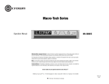
Fig. 4.1 IQ Address Switch (SW1) Location

Page 19
IQ P.I.P.–SMT
Fig. 4.2 IQ Address Switch (SW1)
Values
to set the IQ address of the
IQ–P.I.P.–SMT.
No two IQ
components of the
same type
which are connected to the
same Crown Bus can have
the
same address. Suppose,
for example, the
IQ System
has two Crown Bus loops and
this
IQ–P.I.P.–SMT
is installed
into loop 1 and given address
77. No other
IQ–P.I.P.–SMT
can have the same address
in loop 1. However, an
IQ–
P.I.P.–SMT
in loop 2 can have
the same address.
Different IQ components in
the same Crown Bus loop
can have the same address.
For example, both an
SMX-6
mixer and an
IQ–P.I.P.–SMT
can use address 77 in the
same loop.
A valid IQ address is any
number from 1 to 250. Do not
use a number higher than
250 since they are reserved
for special use. An address
of “0” (zero) should never be
used except to put the
IQ–
P.I.P.–SMT
into a stand-alone
mode where it is invisible to
the
IQ System
and acts as a
“dumb” balanced audio in-
put.
Switch SW1 is located on the
right side on the underside of
the top circuit board (Figure
4.1). It has eight segments
because it actually contains
eight tiny switches inside.
There is an arrow printed on
the switch along its left side
that points to the “ON” posi-
tion and the switches are
numbered along the bottom
(Figure 4.2).
Each of the eight switches in
SW1 has a value which
doubles as the switch num-
ber increases. For example
switch 1 has a value of 1;
switch 2 has a value of 2;
switch 3 has a value of 4;
switch 4 has a value of 8 and
so on.
The address is determined
by adding the values of all
switches which are turned
on. In Figure 4.2 switches 1,
3, 4 and 7 are on. Simply add
the values to find the ad-
dress: 1+4+8+64=77.
A convenient series of IQ ad-
dress tables are included in
Section 7. The tables show
the switch settings for all 250
addresses.
2. Set the input switches S1
and S2. Each input can be
configured for either line-level
or microphone-level signals
with an 8-segment DIP
switch. Phantom power is
also available. Switches S1
and S2 (see Figure 4.3) are
located on the left side of the
lower circuit board. The table
in Figure 4.4 shows how to
set each switch.
IMPORTANT: Two switch

Page 20
IQ P.I.P.–SMT
segments (S1, S2) are re-
quired for each setting. Be
careful to use both segments
or improper operation will re-
sult.
Switch S1 configures the in-
put to Channel 1 and switch
S2 configures the input to
Channel 2.
CAUTION: The
IQ–P.I.P.–
SMT
input preamplifiers
should only be used with
microphone or low-level
signals. Once the
P.I.P.
is in-
stalled, there will be no out-
ward indication of the input
preamplifier gain setting. The
protection circuitry of the am-
plifier will probably be acti-
vated if the preamplifier gain
is set to 40 dB and a line-level
signal is connected to the in-
put. If your amplifier appears
to “cut out” when you drive it
with a strong input signal,
check to see if the input
preamplifier gain is set too
high.
Fig. 4.3 Input Switch (S1, S2) Location
Fig. 4.4 Input Switch (S1, S2) Settings
/