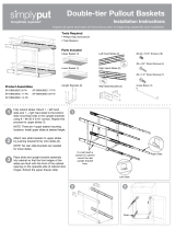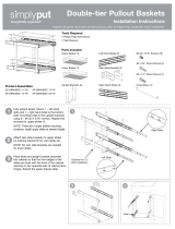
4. Locate sliding bin assembly. Fully extend both sliding members. Separate the slide members by
depressing the disconnect levers on each slide. Set the bin platform aside.
Insert the end of the cabinet slide member into the rear mounting bracket. Align the front end of the
slide over the mark on the cabinet frame, and attach using one (1) #7 pan head sheet metal screw.
Using a second #7 pan head screw, attach the rear of the slide member to the rear mounting bracket.
Repeat this process for remaining sliding member.
5. Align platform assembly slide members in the slide channels of the two slides that were just attached
to the cabinet. Gently push platform fully into cabinet interior. Open and close the assembly to check
for proper fit and operation. Verify slides are level and that the platform slides smoothly and quietly
without binding. If necessary, loosen screws in rear-mounting brackets to adjust position of brackets
to properly align slides. Tighten screws once adjustment is complete.
6. On sliding bin assembly, measure the distance from top edge of bottom cabinet frame rail, to the
bottom most keyholes in slide brackets. This dimension is ˝Y˝. Add the amount of cabinet door
overlay to ˝Y˝. Using this number, mark a horizontal level line across the backside of the cabinet
door, being sure to measure from the bottom of the cabinet door upwards. (FIGURE B)
Measure the distance from the bottom most keyholes in slide brackets to closest side frame edge.
This dimensions is ˝X˝. Add the amount of cabinet door overlay to ˝X˝. Using this number, mark a
vertical level line across the backside of cabinet door on each side, being sure to measure from the
outside edges of cabinet door towards the center of the door. Confirm that on each side of the door,
that this line intersects vertical measurement.
From the locations previously marked for the above, measure up 7-1/2" on either side to locate the
position for upper door bracket keyholes.
7. If your overlay is 1" or less, mount door brackets according to figure C. If your overlay is between
1" and 2", mount door brackets according to FIGURE D. Remove hinges from backside of cabinet
door. Set aside or discard. Laying the brackets on the vertical line on back of cabinet door, center
small round hole over the two intersecting lines. Repeat this process for second bracket on opposite
edge of door.
Using a pencil, mark the screw location in the slotted hole on the bracket, making certain that the
mark is not positioned where it will interfere with the dado of the doorframe, or the center panel. Allow
a minimum of 1/8" clearance from edge of dado. Using two (2) #6-18 x 5/8" flathead sheet metal
screws, attach door bracket to backside of cabinet door using the slotted holes. Repeat this process for
bracket on opposite edge of door. (FIGURE C)
Optional step
Using 1/16" drill bit, drill pilot holes for inserting screws.
8. Insert one (1) #10-24 x 1/4" Phillips pan head machine screw in each round hole of door brackets.
Turn 2 to 3 turns. Extend sliding bin assembly (with slide brackets attached) out of cabinet interior to
a comfortable working position. Align the pan head screws on door bracket with the keyholes in the
slide bracket. Insert through keyhole and push downward until pan head screws are fully seated. If
necessary, loosen the pan head screws slightly to verify screws are fully seated. Tighten screws
to secure.
9. Close cabinet door and sliding assembly. Verify that the door is aligned; side-to-side, up and down as
well as the tilt. To make side-to-side adjustments, loosen and reposition screws in the slotted holes of
the door bracket. If up and down adjustments are necessary, loosen and reposition screws in slotted
holes of door bracket. To make tilt adjustments, loosen and reposition rear-most screws in the top of
the slide brackets (where attached to slide members). Assembly is now complete.
Care & Cleaning
Immediately wipe up spilled liquids and foods.
When cleaning platform assembly, use a clean soft rag dampened with water and a mild dishwashing
detergent.
Sliding members have been lubricated by the manufacturer for optimum performance. Do not remove
lubrication, as it may adversely affect slide performance.
Sliding bin assembly has been thoughtfully designed to reduce contact of clothing and skin with the
lubrication solution used on the sliding members. However, lubrication solution in most cases is not harmful
to skin, and can be removed from skin and or clothing using mild soap.
For best performance when using plastic trash bags, fold excess bag material over top edge of bin and tuck
between bin and the bin access hole in platform to prevent bags from being caught in sliding members.
PULL
PUSH
BACK OF DOOR
Side A
Side B
Side A
Side B
7-1/2"
X
Y
7-1/2"
OVERLAY
OVERLAY
CABINET
OPENING
Y + OVERLAY= BOTTOM HOLE LOCATION
Y + OVERLAY+ 7-1/2" = TOP HOLE LOCATION
X + OVERLAY= DISTANCE FROM SIDE
Side A
Side A
Side B
Side B
BACK OF DOOR
7-1/2"
BACK OF DOOR
7-1/2"
X
Y
7-1/2"
OVERLAY
OVERLAY
CABINET
OPENING
Y + OVERLAY= BOTTOM HOLE LOCATION
Y + OVERLAY+ 7-1/2" = TOP HOLE LOCATION
X + OVERLAY= DISTANCE FROM SIDE
Side A
Side A
Side B
Side B
Side A
Side B
Side A
Side B
7-1/2"
X
Y
7-1/2"
OVERLAY
OVERLAY
CABINET
OPENING
Y + OVERLAY= BOTTOM HOLE LOCATION
Y + OVERLAY+ 7-1/2" = TOP HOLE LOCATION
X + OVERLAY= DISTANCE FROM SIDE
Side A
Side A
Side B
Side B
BACK OF DOOR
7-1/2"
FIGURE B
FIGURE C
FIGURE D


