
MODEL 8183A NETCLOCK/GTP
GPS MASTER CLOCK
INSTRUCTION MANUAL
SPECTRACOM CORPORATION
95 Methodist Hill Drive
Suite 500
Rochester, NY 14623
PHONE 585-321-5800
FAX 585-321-5219
www.spectracomcorp.com
Copyright 2003 Spectracom Corporation. All rights reserved.
Contents of this publication may not be reproduced in any form
without the written permission of Spectracom Corporation.
REVISIONS, IF ANY, ARE LOCATED AT THE END OF THE MANUAL
MANUAL REVISION 1.2
July 2003

5-Year Warranty
SPECTRACOM 95 Methodist Hill Drive ROCHESTER NY 14623 USA
+1.585.321.5800 FAX: +1.585.321.5218 www.spectracomcorp.com sa[email protected]
LIMITED WARRANTY________________________________
Spectracom warrants each new product manufactured and sold by
it to be free from defects in material, workmanship, and
construction, except for batteries, fuses, or other material normally
consumed in operation that may be contained therein, for five
years after shipment to the original purchaser (which period is
referred to as the "warranty period"). This warranty shall not
apply if the product is used contrary to the instructions in its
manual or is otherwise subjected to misuse, abnormal operations,
accident, lightning or transient surge, repairs or modifications not
performed by Spectracom.
The GPS receiver is warranted for one year from date of shipment
and subject to the exceptions listed above. The power adaptor, if
supplied, is warranted for one year from date of shipment and
subject to the exceptions listed above.
The Rubidium oscillator, if supplied, is warranted for two years
from date of shipment and subject to the exceptions listed above.
All other items and pieces of equipment not specified above,
including the antenna unit, antenna surge suppressor and antenna
pre-amplifier are warranted for 5 years, subject to the exceptions
listed above.
WARRANTY CLAIMS________________________________
Spectracom's obligation under this warranty is limited to in-factory
service and repair, at Spectracom's option, of the product or the
component thereof, which is found to be defective. If in
Spectracom's judgment the defective condition in a Spectracom
product is for a cause listed above for which Spectracom is not
responsible, Spectracom will make the repairs or replacement of
components and charge its then current price, which buyer agrees
to pay.
Spectracom shall not have any warranty obligations if the
procedure for warranty claims is not followed. Users must notify
Spectracom of the claim with full information as to the claimed
defect. Spectracom products shall not be returned unless a return
authorization number is issued by Spectracom. Spectracom
products must be returned with the description of the claimed
defect and identification of the individual to be contacted if
additional information is needed. Spectracom products must be
returned properly packed with transportation charges prepaid.
EXCEPT FOR THE LIMITED WARRANTY STATED ABOVE,
SPECTRACOM DISCLAIMS ALL WARRANTIES OF ANY KIND
WITH REGARD TO SPECTRACOM PRODUCTS OR OTHER
MATERIALS PROVIDED BY SPECTRACOM, INCLUDING
WITHOUT LIMITATION ANY IMPLIED WARRANTY OR
MERCHANTABILITY OR FITNESS FOR A PARTICULAR PURPOSE.
Spectracom shall have no liability or responsibility to the original
customer or any other party with respect to any liability, loss, or
damage caused directly or indirectly by an Spectracom product,
material, or software sold or provided by Spectracom,
replacement parts or units, or services provided, including but not
limited to any interruption of service, excess charges resulting from
malfunctions of hardware or software, loss of business or
anticipatory profits resulting from the use or operation of the
Spectracom product or software, whatsoever or howsoever
caused. In no event shall Spectracom be liable for any direct,
indirect, special or consequential damages whether the claims are
grounded in contract, tort (including negligence), or strict liability.
EXTENDED WARRANTY COVERAGE___________________
Extended warranties can be purchased for additional periods
beyond the standard five-year warranty. Contact Spectracom no
later than the last year of the standard five-year warranty for
extended coverage.

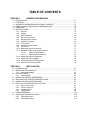
TABLE OF CONTENTS
SECTION 1 GENERAL INFORMATION
1.0 INTRODUCTION...................................................................................................................1-1
1.1 FEATURES ...........................................................................................................................1-2
1.2 WARRANTY INFORMATION AND PRODUCT SUPPORT .................................................1-2
1.3 MANUAL ERRATA AND SPECIAL DOCUMENTATION .....................................................1-3
1.4 UNPACKING.........................................................................................................................1-3
1.5 SPECIFICATIONS ................................................................................................................1-4
1.5.1 Receiver 1-4
1.5.2 Display 1-4
1.5.3 Status Indicators 1-4
1.5.4 RS-232 Serial Comm 1-5
1.5.5 RS-485 Remote Output 1-5
1.5.6 FAA IRIG B Outputs 1-6
1.5.7 1PPS Output 1-6
1.5.8 Standard 10 MHz Output 1-7
1.5.9 Input Power 1-7
1.5.10 Mechanical and Environmental 1-7
1.5.11 Model 8225 GPS Antenna Specifications 1-7
1.5.11.1 Electrical Specifications 1-7
1.5.11.2 Mechanical Specifications 1-8
1.5.12 Model 8226 Impulse Suppressor 1-8
1.5.13 Model 8227 Inline Amplifier 1-8
1.5.14 MP10-0000-0001 Grounding Panel 1-8
1.5.15 CA07xxx GPS Antenna Cable 1-8
SECTION 2 INSTALLATION
2.0 INTRODUCTION................................................................................................................... 2-1
2.1 MODEL 8225 GPS ANTENNA ............................................................................................. 2-1
2.1.1 Antenna Installation 2-1
2.2 ANTENNA CABLE ................................................................................................................ 2-2
2.2.1 Cable Lengths 2-3
2.3 MODEL 8226 IMPULSE SUPPRESSOR ............................................................................. 2-3
2.4 MP10-0000-0001 COPPER GROUNDING PANEL ............................................................. 2-5
2.5 MODEL 8227 GPS INLINE AMPLIFIER............................................................................... 2-6
2.6 NETCLOCK/GPS PREPARATION FOR USE...................................................................... 2-7
2.6.1 Antenna Connection 2-7
2.6.2 Power Connection 2-7
2.6.3 Chassis Ground 2-8
2.6.4 Configuration 2-8
2.7 INITIAL OPERATION............................................................................................................ 2-12
2.8 QUALIFYING THE INSTALLATION ..................................................................................... 2-13
2.8.1 GPS Signal Status 2-13
2.8.2 Tracking Histogram 2-13

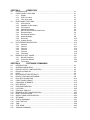
SECTION 3 OPERATION
3.0 INTRODUCTION................................................................................................................... 3-1
3.1 FRONT PANEL FUNCTIONS .............................................................................................. 3-1
3.1.1 Display 3-1
3.1.2 GPS Lock Lamp 3-1
3.1.3 Time Sync Lamp 3-2
3.2 REAR PANEL FUNCTIONS ................................................................................................. 3-3
3.2.1 GPS Antenna 3-3
3.2.2 Standard 10 MHz Output 3-3
3.2.3 1PPS Output 3-3
3.2.4 FAA IRIG B Outputs 3-4
3.2.5 RS-232 Serial Communication Ports 3-5
3.2.6 Remote Outputs 3-6
3.2.7 Serial Setup Interface 3-7
3.2.8 Status Messages 3-8
3.2.9 DC Power 3-10
3.2.10 Chassis Ground 3-10
3.3 DATA FORMAT DESCRIPTION .......................................................................................... 3-10
3.3.1 Format 0 3-11
3.3.2 Format 1 3-13
3.3.3 Format 2 3-14
3.3.4 Format 3 3-16
3.3.5 Format 4 3-18
3.3.6 Format 90 3-19
3.4 REMOTE OUTPUT USAGE ................................................................................................. 3-21
3.4.1 RS-485 Guidelines 3-21
3.4.2 Connection Method 3-22
3.4.3 Termination 3-30
SECTION 4 SOFTWARE COMMANDS
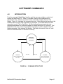
4.0 INTRODUCTION................................................................................................................... 4-1
4.1 ANTENNA CABLE DELAY ................................................................................................... 4-3
4.2 DISPLAY OUTPUT CONFIGURATION................................................................................ 4-4
4.3 DISPLAY ALARM LOG......................................................................................................... 4-5
4.4 DATE..................................................................................................................................... 4-6
4.5 RESTORE FACTORY DEFAULTS....................................................................................... 4-7
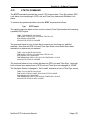
4.6 DISPLAY TRACKING HISTOGRAM .................................................................................... 4-8
4.7 DAYLIGHT SAVING TIME.................................................................................................... 4-10
4.8 FRONT PANEL FORMAT..................................................................................................... 4-13
4.9 GPS SIGNAL STRENGTH ................................................................................................... 4-15
4.10 HELP DISPLAY..................................................................................................................... 4-18
4.11 IRIG CONFIGURATION ....................................................................................................... 4-19
4.12 LOCATION............................................................................................................................ 4-20
4.13 GPS LOCK TIME OUT.......................................................................................................... 4-21
4.14 REMOTE OUTPUT CONFIGURATION ............................................................................... 4-22
4.15 RESET GPS RECEIVER ...................................................................................................... 4-23
4.16 SERIAL COMM CONFIGURATION...................................................................................... 4-24
4.17 SET MODE ........................................................................................................................... 4-26
4.18 STATUS COMMAND............................................................................................................ 4-27
4.19 SYNC TIME OUT .................................................................................................................. 4-28
4.20 TIME...................................................................................................................................... 4-29
4.21 TEST MODE ......................................................................................................................... 4-30
4.22 VERSION COMMAND.......................................................................................................... 4-31

SECTION 5 SERVICE INFORMATION
5.0 INTRODUCTION................................................................................................................... 5-1
5.1 RECEPTION TROUBLESHOOTING.................................................................................... 5-1
5.1.1 No Reception 5-1
5.1.2 Low GPS Quality 5-2
5.2 OSCILLATOR ADJUSTMENT .............................................................................................. 5-4
5.2.1 Adjustment Procedure 5-4
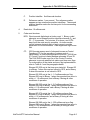
APPENDIX A FAA IRIG CODE DESCRIPTION
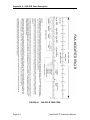
A.0 INTRODUCTION................................................................................................................... A-1
A.1 MODEL 8228 GPS ANTENNA ............................................................................................. A-1
A.1.1 FAA IRIG B General Description A-1

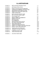
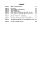
ILLUSTRATIONS
FIGURE 1-1 NETCLOCK/GPS MASTER CLOCK 1-1
FIGURE 2-1 ANTENNA INSTALLATION 2-2
FIGURE 2-2 MODEL 8226 IMPULSE SUPPRESSOR 2-3
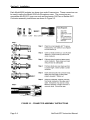
FIGURE 2-3 CONNECTOR ASSEMBLY INSTRUCTIONS 2-4
FIGURE 2-4 GROUNDING PLATE INSTALLATION 2-5
FIGURE 2-5 MODEL 8227 GPS INLINE AMPLIFIER 2-6
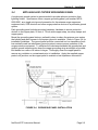
FIGURE 2-6 CABLE GUIDELINES 2-7
FIGURE 3-1 NETCLOCK/GPS FRONT PANEL 3-2
FIGURE 3-2 NETCLOCK/GPS REAR PANEL 3-3
FIGURE 3-3 IRIG CONNECTOR 3-4
FIGURE 3-4 SERIAL COMM PIN NUMBERING 3-5
FIGURE 3-5 REMOTE OUTPUTS 3-6
FIGURE 3-6 RS-485 OUTPUT 3-7
FIGURE 3-7 PIN NUMBERING 3-7
FIGURE 3-8 ONE-WAY BUS INSTALLATION 3-22
FIGURE 3-9 SPLIT BUS CONFIGURATION 3-23
FIGURE 3-10 WIRE STRAIN RELIEF 3-24
FIGURE 3-11 TIMEVIEW RS-485 INTERFACE 3-25
FIGURE 3-12 MODEL 8179T TIMETAP RS-485 INTERFACE 3-25
FIGURE 3-13 MODEL 8188 RS-485 INTERFACE 3-26
FIGURE 3-14 TIMETALK RS-485 INTERFACE 3-26
FIGURE 3-15 TIMEBURST RS-485 INTERFACE 3-27
FIGURE 4-1 COMMAND STRUCTURE 4-1
FIGURE 4-2 TIME DIFFERENCE MAP 4-14
FIGURE A-1 FAA IRIG B TIME CODE A-1

TABLES
TABLE 1-1 MODEL 8183 ANCILLARY KIT 1-3
TABLE 3-1 IRIG PIN OUT 3-4
TABLE 3-2 SERIAL COMM PIN ASSIGNMENTS 3-5
TABLE 3-3 PIN ASSIGNMENTS 3-8
TABLE 3-4 QUALITY INDICATORS 3-15
TABLE 3-5 CABLE SOURCES FOR RS-485 LINES OVER 1500 FEET 3-21
TABLE 3-6 CABLE SOURCES FOR RS-485 LINES UNDER 1500 FEET 3-22
TABLE 4-1 ALPHABETICAL LIST OF COMMANDS 4-2
TABLE 5-1 TYPICAL ANTENNA CABLE RESISTANCE VALUES 5-1
TABLE 5-2 TELEVISION STATIONS WITH GPS JAMMING POTENTIAL 5-3
TABLE 5-3 FM RADIO FREQUENCIES WITH GPS JAMMING POTENTIAL 5-3
TABLE A-1 FAA TIME ERROR INDICATORS A-4

Illustrations road map
FIGURE 1-1 NETCLOCK/GPS MASTER CLOCK
Net-per.cgm
FIGURE 2-1 ANTENNA INSTALLATION 8226_b.eps
FIGURE 2-2 CABLE CLAMP INSTALLATION Net-pc.cgm
FIGURE 3-1 NETCLOCK/GPS FRONT PANEL Net-fr.cgm
FIGURE 3-2 NETCLOCK/GPS REAR PANEL Net-bk.cgm
FIGURE 3-3 SERIAL COMM PIN NUMBERING Femdin.pcx
FIGURE 3-4 REMOTE OUTPUTS Remotout.cgm
FIGURE 3-5 RS-485 OUTPUT Resides in document
FIGURE 3-6 PIN NUMBERING Femdin.pcx
FIGURE 3-7 TIMER RELAY CONTACTS Resides in document
FIGURE 3-8 ALARM RELAY CONTACTS Resides in document
FIGURE 3-9 ONE-WAY BUS INSTALLATION 1way.wmf
FIGURE 3-10 SPLIT BUS CONFIGURATION Splitbus.wmf
FIGURE 3-11 TIMEVIEW RS-485 INTERFACE 81838177.pcx
FIGURE 3-12 MODULAR JACK INTERFACE Gpsmodjk.pcx
FIGURE 3-13 MODEL 8179T TIMETAP RS-485
INTERFACE
81838179.pcx
FIGURE 3-14 TIMETALK RS-485 INTERFACE Resides in document
FIGURE 3-15 TIMEBURST RS-485 INTERFACE 81838185.pcx
FIGURE 4-1 COMMAND STRUCTURE Resides in document
FIGURE 4-2 TIME DIFFERENCE MAP Tzmap.eps (zipped)
FIGURE 5-1 MODEL 8226 IMPULSE SUPPRESSOR Impulseb.eps
FIGURE 5-2 MODEL 8227 INLINE AMPLIFIER Gpsamp.eps
FIGURE 5-3 CABLE GUIDELINES Cablgide.wmf
FIGURE 5-4 MODEL 8213 ANTENNA MOUNT 8226_a.eps
FIGURE A-1 IRIG B TIME CODE Irigb.pcx (zipped)
FIGURE A-2 IRIG E TIME CODE Irige.pcx (zipped)

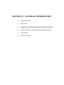
SECTION 1: GENERAL INFORMATION
1.0 INTRODUCTION
1.1 FEATURES
1.2 WARRANTY INFORMATION AND PRODUCT SUPPORT
1.3 MANUAL ERRATA AND SPECIAL DOCUMENTATION
1.4 UNPACKING
1.5 SPECIFICATIONS

NetClock/GTP Instruction Manual Page 1-1
GENERAL INFORMATION
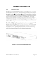
1.0 INTRODUCTION
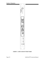
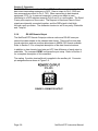
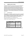
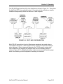
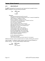
The Spectracom NetClock/GTP Master Clock, shown in Figure 1-1, is a precise,
traceable Global Time Provider. The NetClock/GTP receives and recovers time
information from the Global Positioning System (GPS) constellation of satellites.
The GPS constellation consists of 24 satellites placed in 6 orbital planes spaced
equally around the equator and inclined at a 55-degree angle. This design
assures reliable worldwide coverage 24 hours a day. Each satellite contains a
redundant system of highly accurate and stable atomic clock sources. The
satellite’s timing, orbital position and other system parameters are monitored and
controlled by ground stations maintained by the US Department of Defense and
US Naval Observatory.
The NetClock/GTP Master Clock provides timing outputs accurate to within 100
microseconds of UTC. Standard Master Clock outputs include RS-232,
RS-485, FAA Modified IRIG B and a one pulse per second. The NetClock/GTP
is ideally suited as a Master Clock in all applications requiring an accurate and
traceable time source. Typical applications include computer network timing,
utility billing, financial transactions, public safety and transportation.
FIGURE 1-1 NETCLOCK/GTP MASTER CLOCK

Section 1: General Information
Page 1-2 NetClock/GTP Instruction Manual
1.1 FEATURES
The Spectracom NetClock/GTP offers the following features:
• RELIABLE WORLDWIDE COVERAGE: The NetClock/GTP can receive
and track up to eight satellites simultaneously.
• ACCURACY: The NetClock/GTP 1PPS output is within ± 500
nanoseconds of UTC. The time data outputs are within 100 microseconds
of UTC.
• MULTIPLE TIME DATA OUTPUTS: Each clock includes four FAA
modified pulse width coded IRIG B outputs. Two RS-232 and one RS-485
time data ports are also provided. Output data formats and baud rates are
configured using the RS-232 Setup port.
• REFERENCE FREQUENCY OUTPUT: The NetClock/GTP provides a 10
MHz output disciplined to received GPS signal. Output accuracy is
specified to within ± 1 x 10
-8
.
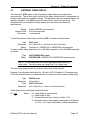
1.2 WARRANTY INFORMATION AND PRODUCT SUPPORT
Warranty information is found on the leading pages of this manual. Should it
become necessary to exercise the warranty, contact Spectracom Corporation to
obtain a replacement or service.
Spectracom continuously strives to improve its products and greatly appreciates
any and all customer feedback. Please direct any comments or questions
regarding application, operation, or service to Spectracom's Customer Service
Department. Customer service is available Monday - Friday from 8:30 A. M. to
5:00 P.M. Eastern Time at 585-321-5800.
In addition, please contact Customer Service to obtain a Return Material
Authorization Number (RMA#) before returning any instrument to Spectracom
Corporation. Please provide the serial number and failure symptoms.
Transportation to the factory is to be prepaid by the customer.
Product support is also available by e-mail. Questions on equipment operation
and applications may be e-mailed to Spectracom at:
Visit our web page for product information, warranty registration, and upgrade
notices as they become available at:
http://www.spectracomcorp.com

Section 1: General Information
NetClock/GTP Instruction Manual Page 1-3
1.3 MANUAL ERRATA AND SPECIAL DOCUMENTATION
Information concerning manual corrections or product changes occurring after
printing is found in the Errata Section. An erratum, when required, is found at the
end of this manual. Please review and incorporate changes into the manual
whenever an Errata Section is included.
Spectracom will make instrument modifications upon special request. The
documentation associated with any modification is provided in addition to this
manual.
1.4 UNPACKING
Upon receipt, carefully examine the carton and its contents. If there is damage to
the carton that results in damage to the unit, contact the carrier immediately.
Retain the carton and packing materials in the event the carrier wishes to witness
the shipping damage. Failing to report shipping damage immediately may forfeit
any claim against the carrier. In addition, notify Spectracom Corporation of
shipping damage or shortages, to obtain replacement or repair services.
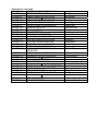
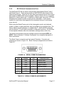
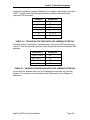
Remove the packing list from the envelope on the outside of the carton. Check
the packing list against the contents to be sure all items have been received,
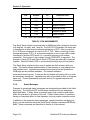
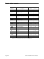
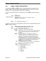
including an instruction manual and ancillary kit. Table 1-1 lists the items
included in the NetClock/GTP ancillary kit.
Description Part Number Quantity
Terminal Block, 3-position P13003 1
Fuse, 1.0 Amp, 3AG F001R0 1
TABLE 1-1 MODEL 8183A ANCILLARY KIT

Section 1: General Information
Page 1-4 NetClock/GTP Instruction Manual
1.5 SPECIFICATIONS
This section contains specifications for the Model 8183A NetClock/GTP, Model
8225 GPS Antenna and antenna accessory products available from Spectracom.
1.5.1 Receiver
Received Standard: L1 C/A Code transmitted at 1575.42 MHz.
Satellites Tracked: Up to eight simultaneously.
Acquisition Time: Typically <20 minutes from cold start.
Acquisition Sensitivity: -105 dBm to -137 dBm.
Tracking Sensitivity: -139 dBm.
Timing Accuracy: <500 nanoseconds with Selective Availability
“SA” on.
Antenna Connector: BNC female.
1.5.2 Display
Display Type: Red LED.
Digit Height: 0.8 inches for day of the year, hours and minutes.
0.56 inches for seconds.
Display Options: 12 or 24-hour format, UTC or local time, enable
DST/STD time changes.
1.5.3 Status Indicators
Front panel bi-color LED’s indicates operational status.
GPS Lock: Indicates GPS satellite tracking status. Lamp is green
when the receiver has tracked at least one satellite
within the period allotted for the GPS Lock Alarm.
The lamp is red during initial operation or whenever a
GPS Lock Alarm or CPU Alarm is asserted. The GPS
Lock Alarm period is programmable up to 23 hours:
59 minutes: 59 seconds in 1-second increments.
Factory default is 15 minutes.

Section 1: General Information
NetClock/GTP Instruction Manual Page 1-5
Time Sync: Indicates accuracy of time data outputs. Lamp is
green when the receiver has tracked at least one
satellite within the period allotted for the Time Sync
Alarm. The lamp is red during initial operation and
when a Time Sync Alarm is asserted. A red lamp
indicates the time data output accuracy may not be
within published specifications. Time Sync Alarm
period is programmable up to 23 hours: 59 minutes:
59 seconds in one-second increments. Factory
default is two hours.
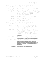
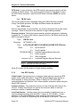
1.5.4 RS-232 Serial Communication Ports
Signal: Selected data format in RS-232 levels when
interrogated by the connected device. The port may
also be configured for continuous once-per-second
output.
Connector: DB9 female, pin assignments conform to EIA/TIA-574
standard, data communication equipment (DCE).
Flow control is not supported.
Character structure: ASCII, 1 start, 8 data, 1 stop, and no parity.
Accuracy: Data stream on time marker within ± 100
microseconds of UTC for Formats 0, 1, 3, and 90
selected. Formats 2 and 4 are within ±1 millisecond
of UTC.
Configuration: Baud rate and output data formats are selected using
the Serial Setup Interface. Bit rate selections are
1200, 2400, 4800 and 9600 baud. There are six data
format selections available. In addition, time zone
offset, DST rule and interrogation character can be
configured. Each RS-232 Serial Comm port is
independently configurable.
1.5.5 RS-485 Remote Output
Signal: Selected data format in RS-485 levels, output once
per second.
Connector: Removable 3-position terminal block (supplied).
Character Structure: ASCII, 1 start, 8 data, 1 stop, and no parity.

Section 1: General Information
Page 1-6 NetClock/GTP Instruction Manual
Accuracy: Data stream on time marker within ± 100
microseconds of UTC for Formats 0, 1, 3, and 90
selected. Formats 2 and 4 are within ±1 millisecond
of UTC.
Configuration: Baud rate and output data formats are selected using
the Serial Setup Interface. Bit rate selections are
1200, 2400, 4800, and 9600 baud. There are six data
format selections available. In addition, time zone
offset and DST rule can be configured.
1.5.6 FAA IRIG B Outputs
Signal: Pulse-width-coded FAA modified IRIG B in RS-
422/485 levels. Four buffered outputs provided. FAA
IRIG B modifications include satellite lock indicator
and error flags between Position Identifiers P5 and P6
and removal of the straight binary seconds data.
Accuracy: ±2 microseconds of UTC when locked to GPS.
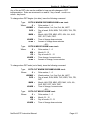
Connector: DB25 Male. Connector pin-out is listed below:
Output 1: Pin 2 (IRIG-B+) Pin 9 (IRIG-B-)
Output 2: Pin 3 (IRIG-B+) Pin 10 (IRIG-B-)
Output 3: Pin 4 (IRIG-B+) Pin 11 (IRIG-B-)
Output 4: Pin 5 (IRIG-B+) Pin 12 (IRIG-B-)
Ground: Pins 1,7,24 and 25.
Configuration: The IRIG time data can be configured to reflect local
time. UTC time zone offset and DST rule selections
are applied to all four IRIG outputs.
1.5.7 1PPS Output
Signal: One pulse-per-second square wave derived from the
GPS receiver.
Signal Level: TTL compatible into high impedance loads, 1.5 V
base-to-peak into 50 ohms.
Pulse Width: 200 milliseconds.
Accuracy: Positive edge within ± 500 nanoseconds of UTC when
locked to GPS.
Connector: BNC female.

Section 1: General Information
NetClock/GTP Instruction Manual Page 1-7
1.5.8 Standard 10 MHz Output
Signal: 10 MHz sinewave.
Signal Level: 350 mVrms into 50 ohms.
Harmonics: Better than 30 dB down.
Spurious: Better than -35 dB down.
Accuracy: ± 1 x 10
-8
when tracking GPS and under constant
temperature and humidity.
Connector: BNC female.
1.5.9 Input Power
DC Input: 12 to 36 VDC, 6 Watts.
Connector: Banana jacks
Polarity: Red is positive (+V), Black is negative (-V).
1.5.10 Mechanical and Environmental
Dimensions: 1.75 H x 19.0 W x 10.0 D inches
(44 H x 483 W x 254 D mm).
Rack mount: EIA 19”, front panel mounting holes for one standard
rack unit.
Weight: 4.25 lbs. (2.0 kg).
Temperature: 0° to 50°C operating range.
1.5.11 Model 8225 GPS Antenna Specifications
1.5.11.1 Electrical Specifications
Type: Active, 30dB gain.
Frequency: 1575.42 MHz.
Temperature Range: -30° to 80° C (-22° to 176°F).
Connector: N type, Female.
Recommended Cable: RG-213.
Maximum Cable Length: 200 feet. Longer cable lengths require the Model
8227 Inline Amplifier.
Power: 5 Volts, 27 milliamps, powered by receiver.

Section 1: General Information
Page 1-8 NetClock/GTP Instruction Manual
1.5.11.2 Mechanical Specifications
Assembled Length: 24 inches (61 cm)
Housing Diameter: 3.5 inches (8.9 cm).
Housing Material: PVC.
Assembled Weight: 1.3 lbs. (.60 kg).
Mounting: Hose clamps (furnished) on vent pipe.
1.5.12 Model 8226 Impulse Suppressor
Connectors: Type N Female.
Turn On Time: 4 nanoseconds for 2 kV/ns.
Turn On Voltage: +7 V, -1 VDC.
Frequency Range: 1.2 to 2.0 GHz.
VSWR: 1.1:1 or better.
Insertion Loss: 0.1 dB maximum.
1.5.13 Model 8227 Inline Amplifier
Connectors: Type N Female.
Gain: 20 ±3 dB.
VSWR: ≤1.5:1.
Power: 3 - 9 VDC, 7.5 ±1 milliamps.
1.5.14 MP10-0000-0001 Grounding Panel
Overall Size: 12.0 L x 18.0 W x 0.75 D inches
(305 H x 457 W x 19 D mm).
Ground Plate Size: 10.0 L x 15.0 W x 0.063 D inches
(254 H x 381 W x 1.6 D mm).
Ground Strap: 20 feet (6 m) of 1.5 inch (38 mm) wide copper strap.
Mounting: Mounting hardware, self-drilling screws, copper
clamps and copper paste are included.
1.5.15 CA07xxx GPS Antenna Coax
Connectors: Type N male both ends.
-FAA suffix changes one end to BNC male.
Cable Jacket: UV resistant, black non-contaminating PVC.
Temperature Range: -40° to 80° C (-40° to 176°F).
Min. Bend Radius: 5.0 inches (127 mm).

SECTION 2: INSTALLATION
2.0 INTRODUCTION
2.1 MODEL 8225 GPS ANTENNA
2.2 ANTENNA CABLE
2.3 MODEL 8226 IMPULSE SUPPRESSOR
2.4 MP10-0000-0001 COPPER GRONDING PANEL
2.5 MODEL 8227 GPS INLINE AMPLIFIER
2.6 NETCLOCK/GPS PREPARATION FOR USE
2.7 INITIAL OPERATION
2.8 QUALIFYING THE INSTALLATION

NetClock/GTP Instruction Manual Page 2-1
INSTALLATION
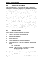
2.0 INTRODUCTION
This section describes the installation of the Model 8225 GPS Antenna and related
accessories. This section also describes the NetClock/GTP preparation for use, initial
operation, installation, qualification and configuration. To ensure proper operation,
please read this section prior to equipment installation and usage.
2.1 MODEL 8225 GPS ANTENNA
The Model 8225 is an active antenna tuned to receive the GPS 1575.42 MHz L1 band
satellite broadcast. The received signals are passed through a narrow bandpass filter
and preamplifier within the antenna. The active antenna circuitry provides 30 dB of gain
and requires +5 VDC at 27 milliamps. This is provided by the NetClock/GTP receiver
over the antenna coax. Each antenna is terminated with a type “N” female connector.
The Model 8225 features a compact weatherproof design measuring 3.5 inches in
diameter.
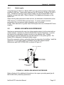
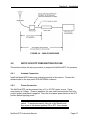
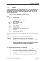
2.1.1 Antenna Installation
The GPS antenna must be installed outdoors in a location where an unobstructed view
of the sky exists. Rooftops generally make good locations due to clear overhead sky
with views to the horizon. This type of location allows the antenna to see and track the
maximum number of satellites throughout the day. Installations with obstructed views
may prove operational, but can experience reduced reception quality and the inability to
simultaneously track the maximum number of satellites. In addition to clear sky
coverage, select a site that would not allow the antenna to become buried in drifted or
accumulated snow or ice. Avoid placing the GPS antenna in close proximity to
broadcast antennas whenever possible.
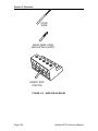
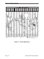
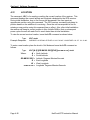
Each antenna includes a mating PVC mast assembly and two hose clamps to simplify
installation. The hose clamps can be used to affix the mast assembly to a vent pipe.
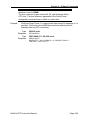
Spectracom offers an antenna base, Model 8213, for installations where vent pipe
mounting is not practical or desired. The Model 8213 is constructed of aluminum and is
furnished with ballast for stability. Both mounting methods are illustrated in Figure 2-1.

Section 2: Installation
Page 2-2 NetClock/GTP Instruction Manual
FIGURE 2-1 ANTENNA INSTALLATION
2.2 ANTENNA CABLE
Spectracom recommends RG-213 type coax, such as Belden 8267, for the GPS
antenna cable. To simplify the installation process, Spectracom offers GPS cable
assemblies terminated with Type N male or BNC male connectors. Specify part number
CA07xxx, where xxx equals the length in feet, for a cable terminated with Type N
connectors. Adding the suffix –FAA changes one end of the antenna cable assembly to
a BNC male connector.
If the antenna cable is purchased locally, select coax suitable for outdoor use. Consider
the cable's weather resistance, temperature range, UV resistance, and attenuation
characteristics.
Do not allow the antenna cable to be placed in standing water, as water may permeate
through the coax jacket over time. On flat roof installations, the coax can be suspended
by cable hangers or placed in sealed PVC conduit. Apply a weather proofing sealant or
tape over all outdoor connections.
Installation of a surge protection device in the antenna line is recommended to protect
the NetClock/GTP receiver and connected devices from lightning damage. Spectracom
offers the Model 8226 Impulse Suppressor to shunt potentially damaging voltages on
the antenna coax to ground. Refer to Section 2.3 for a complete description of the
Model 8226.
Page is loading ...
Page is loading ...
Page is loading ...
Page is loading ...
Page is loading ...
Page is loading ...
Page is loading ...
Page is loading ...
Page is loading ...
Page is loading ...
Page is loading ...
Page is loading ...
Page is loading ...
Page is loading ...
Page is loading ...
Page is loading ...
Page is loading ...
Page is loading ...
Page is loading ...
Page is loading ...
Page is loading ...
Page is loading ...
Page is loading ...
Page is loading ...
Page is loading ...
Page is loading ...
Page is loading ...
Page is loading ...
Page is loading ...
Page is loading ...
Page is loading ...
Page is loading ...
Page is loading ...
Page is loading ...
Page is loading ...
Page is loading ...
Page is loading ...
Page is loading ...
Page is loading ...
Page is loading ...
Page is loading ...
Page is loading ...
Page is loading ...
Page is loading ...
Page is loading ...
Page is loading ...
Page is loading ...
Page is loading ...
Page is loading ...
Page is loading ...
Page is loading ...
Page is loading ...
Page is loading ...
Page is loading ...
Page is loading ...
Page is loading ...
Page is loading ...
Page is loading ...
Page is loading ...
Page is loading ...
Page is loading ...
Page is loading ...
Page is loading ...
Page is loading ...
Page is loading ...
Page is loading ...
Page is loading ...
Page is loading ...
Page is loading ...
Page is loading ...
Page is loading ...
Page is loading ...
Page is loading ...
Page is loading ...
Page is loading ...
Page is loading ...
Page is loading ...
Page is loading ...
Page is loading ...
Page is loading ...
Page is loading ...
Page is loading ...
Page is loading ...
Page is loading ...
Page is loading ...
Page is loading ...
-
 1
1
-
 2
2
-
 3
3
-
 4
4
-
 5
5
-
 6
6
-
 7
7
-
 8
8
-
 9
9
-
 10
10
-
 11
11
-
 12
12
-
 13
13
-
 14
14
-
 15
15
-
 16
16
-
 17
17
-
 18
18
-
 19
19
-
 20
20
-
 21
21
-
 22
22
-
 23
23
-
 24
24
-
 25
25
-
 26
26
-
 27
27
-
 28
28
-
 29
29
-
 30
30
-
 31
31
-
 32
32
-
 33
33
-
 34
34
-
 35
35
-
 36
36
-
 37
37
-
 38
38
-
 39
39
-
 40
40
-
 41
41
-
 42
42
-
 43
43
-
 44
44
-
 45
45
-
 46
46
-
 47
47
-
 48
48
-
 49
49
-
 50
50
-
 51
51
-
 52
52
-
 53
53
-
 54
54
-
 55
55
-
 56
56
-
 57
57
-
 58
58
-
 59
59
-
 60
60
-
 61
61
-
 62
62
-
 63
63
-
 64
64
-
 65
65
-
 66
66
-
 67
67
-
 68
68
-
 69
69
-
 70
70
-
 71
71
-
 72
72
-
 73
73
-
 74
74
-
 75
75
-
 76
76
-
 77
77
-
 78
78
-
 79
79
-
 80
80
-
 81
81
-
 82
82
-
 83
83
-
 84
84
-
 85
85
-
 86
86
-
 87
87
-
 88
88
-
 89
89
-
 90
90
-
 91
91
-
 92
92
-
 93
93
-
 94
94
-
 95
95
-
 96
96
-
 97
97
-
 98
98
-
 99
99
-
 100
100
-
 101
101
-
 102
102
-
 103
103
-
 104
104
-
 105
105
-
 106
106


Spectracom 8183A NetClock/GTP GPS Master Clock User manual
- Type
- User manual
- This manual is also suitable for
Ask a question and I''ll find the answer in the document
Finding information in a document is now easier with AI
Related papers


Other documents
-
 Orolia 8183 NetClock/GPS GPS Master Clock User manual
-
 Orolia NetClock/GPS 9283 User manual
-
 Orolia NetClock Time Server 9300 Series User manual
-
 Orolia 9183 NetClock/GPS Master Clock User manual
-
 Orolia TTS 240 Network Time Server User manual
-
 Orolia 8179T TimeTap Port-Powered Converter User manual
-
Legrand Satellite Surge Protector, IS-0285 Installation guide
-
 Orolia 8182 NetClock/2 WWVB Synchronized Master Clock User manual
-
 Orolia NetClock 9400 Series Time Server User manual
-
 Orolia 8189 NetClock/NTP Network Time Provider User manual


