Page is loading ...

Installation
Operation
Maintenance
RTUB 207-224 - Liquid chillers with
helical rotary compressors
RTCA 108-216 - Remote air-cooled
condenser
RLC-SVX03A-E4

RLC-SVX03A-E4
Foreword
These installation, operation and
maintenance instructions are given
as a guide to good practice in the
installation, putting into service,
operation, and maintenance by the
user of Trane RTUB and RTCA units.
They do not contain full service
procedures necessary for the
continued successful operation of
this equipment; The services of a
qualified technician should be
employed through the medium of a
maintenance contract with a
reputable service company.
Warranty
Warranty is based on the general
terms and conditions of Société
Trane or Trane UK Ltd. The warranty
is void if the equipment is repaired
or modified without the written
approval of Trane, if the operating
limits are exceeded or if the control
system or the electrical wiring is
modified.
Damage due to misuse, lack of
maintenance or failure to comply
with the manufacturer's instructions
or recommendations is not covered
by the warranty obligation.
If the user does not conform to the
rules of chapter "Maintenance", it
may entail cancellation of warranty
and liabilities by Trane.
Reception of the
unit
On arrival, inspect the unit before
signing the delivery note. Specify
any damage on the delivery note,
and send a registered letter of
protest to the last carrier of the
goods within 72 hours of delivery.
Notify the local Trane Sales Office at
the same time. The unit should be
totally inspected within 7 days of
delivery. If any concealed damage is
discover, send a registered letter of
protest to the carrier within 7 days of
delivery and notify the local Trane
Office.
Units are shipped with the
refrigerant operating or holding
charge and should be examined with
an electronic leak detector to
determine the hermetic integrity of
the unit. The refrigerant charge is not
included in the standard Trane
Warranty Cover.
Cautions and
warnings
Cautions and warnings appear at
appropriate places in this instruction
manual. Your personal safety and the
proper operation of this machine
require that you follow them
carefully. The constructor assumes
no liability for installations or
servicing performed by unqualified
personnel.
Refrigerant
The refrigerant provided by Société
Trane or Trane UK Ltd meets all the
requirements of our units. When
using recycled or reprocessed
refrigerant, it is advisable to ensure
its quality is equivalent to that of a
new refrigerant. For this, it is
necessary to have a precise analysis
made by a specialized laboratory. If
this condition is not respected, the
Société Trane UK Ltd warranty could
be cancelled.
©American Standard Inc. 2002

RLC-SVX03A-E4 3
Contents
Foreword 2
Warranty 2
Reception of unit 2
Cautions and warnings 2
Refrigerant 2
General information
Unit Inspection 5
Inspection Checklist 5
Loose Parts Inventory 6
Description of the Unit 6
General Data RTUB 7
General Data RTCA 8
Installation
Installation Responsibilities 9
Storage 9
Special Lifting and Moving Instructions 10
Isolation 10
Foundation 10
Clearances 11
Drainage 12
Releasing the Nitrogen Holding Charge 12
Water Connections (RTUB) 12
Flow Switch Installation 13
Water Pressure Gauges 13
Refrigeration Safety Valves 14
Water Pressure Relief Valves 14
Installing and Connecting Temperature Sensors 14
Connecting RTUB with the Remote Air-cooled Condenser 15

4
Operation
Pre-start Checkout 21
Unit Voltage Power Supply 21
Unit Voltage Imbalance 21
Unit Voltage Phasing 21
Water System Flow Rates 22
Water System Pressure Drop 22
Daily Unit Start-up Procedure 22
Seasonal Unit Start-up Procedure 23
Temporary Shutdown and Restart 23
Extended Shutdown Procedure 23
System Restart after Extended Shutdown 23
Maintenance
Periodic Maintenance 25
Refrigerant and Oil Charge Management 27
R134a Field-charging Procedure 28
Charge Isolation on the High or Low Side of the System 28
Filter Replacement Procedure 29
Lubrication System 29
Oil Charging Procedure 29
Safety Recommendations 32
Maintenance Contract 32
Training 32
CG-PRC010-E4
Contents

RLC-SVX03A-E4
5
General information
This manual describes installation,
operation, and maintenance of RTUB
and RTCA units.
A separate manual is available for
the use and maintenance of the
RTUB controls (UCM-CLD).
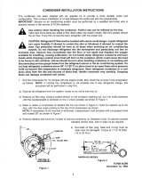
Unit Inspection
When the unit is delivered, verify
that it is the correct unit and that it is
property equipped. Compare the
information that appears on the unit
nameplate with the ordering and
submittal information. A typical unit
nameplate is shown in Figure 1.
Inspect all exterior components for
visible damage. Report any apparent
damage or material shortage to the
carrier and make a "unit damage"
notation on the carrier's delivery
receipt. Specify the extent and type
of damage found and notify the
appropriate Trane Sales Office. Do
not proceed with installation of a
damaged unit without sales office
approval.
Inspection Checklist
To protect against loss due to
damage incurred in transit, complete
the following checklist upon receipt
of the unit.
• Inspect the individual pieces of the
shipment before accepting the unit.
Check for obvious damage to the
unit or packing material.
• Inspect the unit for concealed
damage as soon as possible after
delivery and before it is stored.
Concealed damage must be
reported within 15 days.
If concealed damage is discovered,
stop unpacking the shipment. Do not
remove damaged material from the
receiving location. Take photos of the
damage, if possible. The owner must
provide reasonable evidence that the
damage did not occur after delivery.
• Notify the carrier's terminal of the
damage immediately, by phone and
by mail. Request an immediate,
joint inspection of the damage with
the carrier and the consignee.

6
• Notify the Trane sales
representative and arrange for
repair. Do not repair the unit,
however, until damage is inspected
by the carrier's representative.
Loose Parts Inventory
Check all the accessories and loose
parts that are shipped with the unit
against the shipping list. Included in
these items will be water vessel
drain plugs, rigging and electrical
diagrams, and service literature,
which are placed inside the control
panel and/or starter panel for
shipment.
Description of the Unit
The RTUB units are liquid chillers
equipped with two helical rotary
compressors and an evaporator
designed to operate with remote
RTCA air-cooled condensers or other
manufacturers' remote condensers.
The RTUB is shipped once it has
been assembled and wired in the
factory. The discharge piping is
blocked at the oil separator outlet.
Water connections - chilled water
inlet and outlet - are blocked for
transportation. Both RTUB and RTCA
units are dried and vacuum-pumped
in the factory, and contain a nitrogen
holding charge when shipped.
General information
RLC-SVX03A-E4
é
RTCA
RTUB
Figure 1 - Typical Unit Nameplates

7
Table 1 - General data - RTUB
Unit size 207 208 210 211 212 214
Compressor
Type/quantity Helical rotary/2
Nominal size (tons) 35/35 40/40 50/50 60/50 60/60 70/70
Evaporator
Evaporator Model EG 120 EG 120 EG 140 EG 170 EG 170 EG 200
Water Storage (l) 105 105 365 220 220 200
Minimum Flow (l/s) 4.5 4.5 6.0 7.0 7.0 9.0
Maximum Flow (l/s) 13.4 13.4 18.0 21.0 21.0 25.0
Evaporator inlet diameter (inches) 556666
Evaporator outlet diameter (inches) 556666
Minimum Starting/
Operating Ambient (°C) 5
Refrigerant R134a
Number of Independent
Refrigerant Circuits 2
Percent Minimum Load (%) 17
Refrigerant Charge (kg) 26 26 40 40 40 40
Oil Charge (l) 12 12 14 14 14 16
Operating Weight (kg) 2130 2130 2845 2845 2845 3250
Shipping Weight (kg) 1860 1860 2570 2570 2570 2975
Unit size 216 217 218 220 222 224
Compressor
Type/Quantity Helical rotary/2
Nominal size (tons) 70/85 85/85 100/85 100/100 120/100 120/120
Evaporator
Evaporator Model EG 200 EG 200 EG 250 EG 250 EG 340 EG 340
Water Storage (l) 200 200 415 415 560 560
Minimum Flow (l/s) 9.0 9.0 11.0 11.0 14.0 14.0
Maximum Flow (l/s) 25.0 25.0 33.0 33.0 43.0 43.0
Evaporator inlet diameter (inches) 666666
Evaporator outlet diameter (inches) 666666
Minimum Starting/
Operating Ambient (°C) 5
Refrigerant R134a
Number of Independent
Refrigerant Circuits 2
Percent Minimum Load (%) 17
Refrigerant Charge (kg) 40 40 46 46 50 50
Oil Charge (l) 16 16 16 16 19 22
Operating Weight (kg) 3250 3250 3880 4050 4480 4550
Shipping Weight (kg) 2975 2975 3405 3575 3855 3925
General information
RLC-SVX03A-E4

RLC-SVX03A-E4
8
General information
Table 2 - General data - RTCA
Unit size 108 109 111 113 115 116
Condenser
Condenser type Aluminium fins/copper tubes
Fin spacing (fins/ft) 168 168 144 168 168 144
Frontal surface area (m²) 5.7 6.9 6.9 11.3 11.7 13.7
Airflow
Standard unit (m
3
/h) 42500 50400 69300 77200 84700 98500
Low noise unit (m
3
/h) 34500 40900 56300 62700 68800 80000
Condenser fans
Number of fans 4468812
Fan speed
Standard unit (rpm) 690
Low noise unit (rpm) 560
Nominal fan power
Standard unit (kW) 0.85
Low noise unit (kW) 0.54
Current fan amps
Standard unit (A) 2.4
Low noise unit (A) 1.2
Minimum Starting/
Operating Ambient (1) (°C) 7 Standard units/-18 Low ambient units
Refrigerant R134a
Number of Independent
Refrigerant Circuits 111111
Refrigerant Charge (kg) 22 26 36 44 52 72
Operating Weight (2) (kg) 810 890 1090 1535 1770 2050
Shipping Weight (2) (kg) 1020 1100 1300 1870 2170 2450
Hot gas connection (inches) 1 5/8 1 5/8 1 5/8 1 5/8 1 5/8 1 5/8
Liquid connection (inches) 1 1/8 1 1/8 1 1/8 1 1/8 1 1/8 1 1/8
Unit size 208 209 211 213 215 216
Condenser
Condenser type Aluminium fins/copper tubes
Fin spacing (fins/ft) 168 168 144 168 168 144
Frontal surface area (m²) 5.7 6.9 6.9 11.3 11.7 13.7
Airflow
Standard unit (m
3
/h) 42500 50400 69300 77200 84700 98500
Low noise unit (m
3
/h) 34500 40900 56300 62700 68800 80000
Condenser fans
Number of fans 2 x 2 2 x 2 2 x 3 2 x 4 2 x 4 2 x 6
Fan speed
Standard unit (rpm) 690
Low noise unit (rpm) 560
Nominal fan power
Standard unit (kW) 0.85
Low noise unit (kW) 0.54
Current fan amps
Standard unit 2.4
Low noise unit 1.2
Minimum Starting/
Operating Ambient (1) (°C) 7 Standard units/-18 Low ambient units
Refrigerant R134a
Number of Independent
Refrigerant Circuits 222222
Refrigerant Charge (kg) 2 x 11 2 x 13 2 x 18 2 x 22 2 x 26 2 x 36
Operating Weight (2) (kg) 810 890 1090 1535 1770 2050
Shipping Weight (2) (kg) 1020 1100 1300 1870 2170 2450
Hot gas connection (inches) 1 5/8 1 5/8 1 5/8 1 5/8 1 5/8 1 5/8
Liquid connection (inches) 1 1/8 1 1/8 1 1/8 1 1/8 1 1/8 1 1/8
(1) Based on a 2.2 m/s wind across the condenser
(2) With aluminium fins

RLC-SVX03A-E4
9
Installation responsibilities
Generally, the contractor must do the
following when installing an
RTUB/RTCA unit.
• Install the units on a flat
foundation, level (within 1/4"
[6 mm] across the length of the
unit), and strong enough to support
unit loading.
• Install the units per the instructions
contained in the Installation section
of this manual.
• Install any optional sensors and
make electrical connections at the
UCM-CLD.
• Where specified for the RTUB,
provide and install valves in the
water piping upstream and
downstream of the evaporator
water connections, to isolate the
evaporator for maintenance and to
balance and trim the system.
• Furnish and install a flow switch
and/or auxiliary contacts to prove
chilled-water flow.
• Furnish and install pressure gauges
in the inlet and outlet piping of the
evaporator (for RTUB).
• Furnish and install a drain valve to
the bottom of the evaporator water
box (for RTUB).
• Supply and install a vent cock to the
top of the evaporator water box (for
RTUB).
• Furnish and install strainers ahead
of all pumps and automatic
modulating valves.
• Furnish and install check valves on
the discharge lines (between oil
separators and condenser) in order
to avoid any refrigerant migration
leading to catastrophic damages to
evaporator and/or compressor (due
to freeze-up or liquid slugging).
• Interconnect the RTUB and the
remote condenser.
• Provide and install field wiring.
• Install heat tape and insulate the
chilled-water lines and any other
portions of the system, as required,
to prevent sweating under normal
operating conditions or freezing
during low-ambient temperature
conditions.
• Start the unit under the supervision
of a qualified service technician.
Storage
If the chiller is stored for a long period
of time prior to installation, the
following precautionary measures must
be taken:
• Store the unit in a safe place
sheltered from bad weather
• At least every three months
(quarterly), check the pressure in
the refrigerant circuits to verify that
the nitrogen holding charge is
intact. If it is not, contact a qualified
service organization and the
appropriate Trane sales office.
• Close the discharge and liquid-line
isolation valves.
Installation

10
Special Lifting and Moving
Instructions
A specific lifting method is
recommended as follows:
1. Four lifting points are built into the
unit.
2. Slings and spreader bar to be
provided by rigger and attached to
the four lifting points.
3. Minimum rated lifting capacity
(vertical) of each sling and
spreader bar shall be no less than
the tabulated unit shipping weight.
CCAAUUTTIIOONN
This unit must be lifted with the
utmost care. Avoid shock load by
lifting slowly and evenly.
WWAARRNNIINNGG
To prevent any damage, position the
lifting bar so that the slings do not
touch the unit.
Isolation
The most effective form of isolation
is to locate the unit away from any
sound-sensitive area. Structurally
transmitted sound can be reduced by
elastomeric vibration eliminators.
Spring isolators are not
recommended for units equipped
with helical rotary compressors.
Consult an acoustical engineer in
critical sound applications. For
maximum isolation effect, isolate
water lines and electrical conduit.
Wall sleeves and rubber- isolated
piping hangers can be used to
reduce the sound transmitted
through water piping. To reduce the
sound transmitted through electrical
conduit, use flexible electrical
conduit. State and local codes on
sound emissions should always be
considered.
Foundation
Provide rigid, non-warping mounting
pads or a concrete foundation of
sufficient strength and mass to
support the unit's operating weight
(that is, including completed piping,
and full operating charges of
refrigerant, oil, and water). After it is
in place, the unit must be level
within 1/4" [6 mm] over its length
and width. Use shims if necessary.
The manufacturer is not responsible
for equipment problems resulting
from an improperly designed or
constructed foundation.
Note for RTCA: The unit must be
positioned so that the airflow
through the condensation coils is not
hindered by any obstacle. The
Installation
Figure 2- Rigging the unit - RTUB 207-208 Figure 3- Rigging the unit - RTUB 210-224 Figure 4- Rigging the unit - RTCA 108-216
Table 3 - Sling Lengths (mm) for lifting
ABCDE
RTUB unit size
207-208 2200 3000 2600 2100 -
210-211-212 2400 3000 2550 3150 3650
214-216-217 2500 3000 2550 3150 3650
218-220 2450 3050 2600 3150 3650
222-224 2450 3100 2650 3150 3650
RTCA unit size
108/109/111/208/209/211 2240 1700 1700 - -
113/115/115/213/215/216 2240 2800 2800 - -
RLC-SVX03A-E4

11
Installation
condensation coils must be
protected from side winds when
their speed exceeds 16 km/h.
Position the unit above the average
height of snow observed in the
region where it is installed. Never
install temporary or permanent
objects (tarp or roof) over the unit,
because recycling of hot air would
reduce the capacity of the
condensation coils. Discharged air
from the fans must not be
obstructed. It is prohibited to install
ducts for the fan discharge air (even
short ones). This is because the fans
supplied on standard units do not
generate any additional static
pressure.
Clearances
Provide enough space around the
unit to allow the installation and
maintenance personnel unrestricted
access to all service points. Refer to
Figure 5 and Table 4 for unit
Figure 5: Unit Dimensions and
Recommended Minimum
Clearances - RTCA
Figure 6: Unit Dimensions and
Recommended Minimum
Clearances - RTUB
A
C
D
B
A
C
D
B
Table 4 - Unit Dimensions and Recommended Minimum Clearances (mm)
Length Width Height A B C D
RTCA 108/109/111/208/209/211 2870 2285 1630 1000 1000 1000 1000
RTCA 113/213 4610 2285 1630 1000 1000 1000 1000
RTCA 115/116/215/216 5450 2285 1630 1000 1000 1000 1000
RTUB 207/208 2880 890 1789 950 800 1800 500
RTUB 210/211/212/214/216/217 4150 890 1832 950 800 2750 500
RTUB 218/220 4150 890 1932 950 800 2750 500
RTUB 222/224 4150 890 2041 950 800 2750 500
dimensions and recommended
clearances. Unobstructed flow of
condenser air is essential to maintain
chiller capacity and operating
efficiency.
Note for RTCA: When determining
unit placement, give careful
consideration to ensuring a sufficient
flow of air across the condenser
heat-transfer surface.
RLC-SVX03A-E4

12
Drainage
Provide a large-capacity drain for
water vessel drain-down during
shutdown or repair. The evaporator
is provided with a drain connection.
All local and national codes apply.
The vent on the top of the
evaporator water box is provided to
prevent a vacuum, by allowing air
into the evaporator for complete
drainage.
Releasing the Nitrogen
Holding Charge
The nitrogen holding charge can be
released into the atmosphere.
CCAAUUTTIIOONN
When releasing nitrogen holding
charge, ventilate the room. Avoid
breathing in the nitrogen.
Water Connections (RTUB)
Thoroughly flush all water piping to
the unit before making the final
piping connections to the unit.
CCAAUUTTIIOONN
If using an acidic commercial
flushing solution, construct a
temporary bypass around the unit to
prevent damage to internal
components of the evaporator. To
avoid possible equipment damage,
do not use untreated or improperly
treated system water.
When making the water connections,
use flange connectors. Insulate all
piping to reduce temperature
increases and to prevent
condensation. Figure 7 shows all the
piping systems for the evaporator
and its components. The
arrangement of the pipes and the
other components varies slightly
according to the positioning of the
connections and the water source.
CCAAUUTTIIOONN
The chilled water connections to the
evaporator are Victaulic connections.
Do not attempt to weld these
connections, because the heat
generated from welding can cause
microscopic and macroscopic
fractures on the cast- iron water
boxes that can lead to premature
failure of the water box.
A vent line is located on the top part
of the evaporator at the water return
piping end. Install additional vent
lines at the highest points in the
piping to vent the air present in the
chilled water circuit. Install
manometers to monitor the pressure
of chilled water entering and leaving
the evaporator.
CCAAUUTTIIOONN
To prevent damage to chilled-water
components, do not allow
evaporator pressure (maximum
working pressure) to exceed 10.5
bars.
Provide shutoff valves in lines to the
gauges, in order to isolate them from
the system when they are not in use.
Use rubber vibration eliminators to
prevent vibration transmission
through the water lines. If desired,
install thermometers in the lines to
monitor entering- and leaving-water
temperatures. Install a balancing
valve in the leaving-water line to
control water flow balance. Install
shutoff valves on both the entering-
and leaving-water lines so that the
evaporator can be isolated for
service. A pipe strainer must be
installed in the entering water line.
Failure to do so can allow
waterborne debris to enter the
evaporator.
"Piping components" include all
devices and controls used to provide
proper water system operation and
unit operating safety. These
components and their general
locations are given in Figure 7.
Entering Chilled-Water Piping
• Air vents (to bleed air from system).
• Water pressure gauges with shutoff
valves.
• Vibration eliminators.
• Shutoff (isolation) valves.
• Thermometers (if desired).
• Clean out tees.
• Pipe strainer.
CCAAUUTTIIOONN
Install a strainer in the evaporator-
water inlet piping. Failure to do so
can result in evaporator tube
damage.
Leaving Chilled-Water Piping
• Air vents (to bleed air from system).
• Water pressure gauges with shutoff
valves.
• Vibration eliminators.
• Shutoff (isolation) valves.
• Thermometers (if desired).
• Clean out tees.
• Balancing valve.
• Flow Switch
Evaporator Drain
A 3/4" drain connection is located
under the outlet end of the
evaporator water box. This may be
connected to a suitable drain to
permit evaporator drainage during
unit servicing. A shutoff valve must
be installed on the drain line.
Evaporator Flow Switch (accessory)
The chilled water flow is protected
by the UCM-CLD without the
assistance of a chilled water flow
switch. The flow switch is optional,
but if it is not installed, a signal must
be sent to the chiller to indicate the
water flow is established, for
example the auxiliary contacts of the
chilled water pump starter.
If additional protection of the chilled
water flow proves necessary,
connect a flow switch installed on
site, or a differential pressure switch
to control the system's water flow.
Connect the flow switch in series
with the auxiliary contacts of the
chilled water pump motor starter. A
special connector is supplied with
the unit, with the wiring diagrams.
Some piping and control schemes,
particularly those using a single
water pump for both chilled- water
and hot water, must be analyzed to
determine how and/or if a flow-
sensing device will provide the
desired operation.
Installation
RLC-SVX03A-E4

13
Follow the manufacturer's
instructions for the installation
procedures.
Flow Switch Installation
1. Mount the switch upright, with a
minimum of 5 pipe diameters of
straight horizontal run on each
side. Do not install close to
elbows, orifices, or valves. Note:
The arrow on the switch must
point in the direction of flow.
2. To prevent switch fluttering,
remove all air from the water
system. Note: The UCM-CLD waits
for six seconds after a “flow loss”
diagnosis before stopping the unit.
Contact a qualified service
representative if nuisance machine
shutdowns persist.
3. Adjust the switch to open when
water flow falls below nominal.
Evaporator data is given in Table 1.
Flow-switch contacts are closed on
proof of water flow.
4. Install a pipe strainer in the
entering evaporator-water line to
protect components from
waterborne debris.
Water Treatment
CCAAUUTTIIOONN
If calcium chloride is used for waste
treatment, an applicable corrosion
inhibitor must also be used. Failure
to do so may result in damage to
system components. Dirt, scale,
products of corrosion, and other
foreign material will adversely affect
heat transfer between the water and
system components. Foreign matter
in the chilled-water system can also
increase pressure drop and,
consequently, reduce water flow.
Proper water treatment must be
determined locally, depending on the
type of system and local water
characteristics. Neither salt nor
brackish water is recommended for
use in Trane units. Use of either will
lead to a shortened life to an
indeterminable degree. The Trane
Company encourages the
employment of a reputable water
treatment specialist, familiar with
local water conditions, to assist in
this determination and in the
establishment of a proper water-
treatment program.
Water Pressure Gauges
Install field-supplied pressure
components as shown in Figure 7.
Locate pressure gauges or taps in a
straight run of pipe; avoid placement
near elbows, and so forth. Be sure to
install the gauges at the same
elevation on each shell if the shells
have opposite-end water
connections. Note: After the unit is
installed at a site, one vertical (or one
diagonal) unit support can be
permanently removed if it creates an
obstruction for water piping. To read
Installation
7
6
5
4
6
2
1
9
10
3
8
Figure 7 - Typical piping of the evaporator (RTUB)
1 Air vent
2 Balance valve
3 Flow switch
4 Thermometers
5 Expansion joints
6 Stop valves
7 Manometer
8 Evaporator
9 Filter
10 Drainage
RLC-SVX03A-E4

14
Installation
the values given by the pressure
gauges, open one valve and close
the other.
Refrigerant Safety Valves
Discharge valves are an option for
the RTUB. If installation requires this
valve to be mounted, it is mandatory
to install two safety valves: one
between the compressor and the
service valve and the other after the
service valve to protect the
condenser.
CCAAUUTTIIOONN
The safety valve calibration must not
exceed 25 bars. The liquid line must
be connected at the inlet to the drier
filter which is supplied with a bend
blocked by a brazed plug. The
connection piping must be correctly
dimensioned and installed, because
these factors have a substantial
impact on the system's performance
and reliability.
Water Pressure-Relief
Valves
CCAAUUTTIIOONN
To prevent shell damage, install
pressure-relief valves in the
evaporator water system. Install a
water pressure-relief valve in the
evaporator inlet piping, between the
evaporator and the inlet shutoff
valve. Water vessels with close-
coupled shutoff valves have a high
potential for hydrostatic pressure
buildup on a water temperature
increase. Refer to applicable codes
for relief-valve installation
guidelines.
Installing and connecting
temperature sensors
General Recommendations
Regardless of the type of monitoring
sensor required by a particular
application, the sensor must always
be positioned far enough from the
evaporator or condenser to enable
the sensor to read a correct
temperature for the mixed water.
Install the sensor at 4 o'clock on the
water piping to prevent any
condensation. When installing
standard or optional temperature
sensors described in the following
paragraphs, comply with the
instructions:
Put thermocontact paste in each
sensor bulbwell before inserting the
sensor. All the temperature sensors
installed on site have an
identification number and a serial
number marked on the part body.
Also note that both sensors in each
pair have the same serial number.
WWAARRNNIINNGG
To prevent degraded operation due
to electrical interference, run the
sensor cables in a duct. However, do
not lay sensor cables with other
cables whose voltage is greater than
30 VAC.
Extension of sensor power cable
A temperature sensor's power cable
may not be long enough to reach the
UCM. If this is the case for your
installation, connect the cable to a
junction box installed in a more
Figure 8- RTUB Evaporator water pressure drops
Evaporator Water Pressure Drop
Water Flow Rate l/s
kPa
RLC-SVX03A-E4

15
Installation
withstanding high temperatures
without degradation.
CCAAUUTTIIOONN
A defect in fixing or insulating the
condensation sensors may cause
incorrect adjustment and/or damage
to the compressor.
If the sensor cannot be mounted in
the place where the saturated gas
enters the sub-cooler, it must be
positioned on the sub-cooler side
and not on the condenser side. If the
condenser temperature cannot be
measured, it is preferable to
measure the liquid temperature
instead of the discharge
temperature.
CCAAUUTTIIOONN
To prevent interference, separate the
sensor cables from the power cables.
Electrical connections
performed by the installer
All wiring must comply with local
codes. Specific electrical schematics
and connection diagrams are
shipped with the unit.
CCAAUUTTIIOONN
To avoid corrosion and overheating
at terminal connections, use copper
conductors only. Failure to do so
may result in damage to the
equipment. Do not allow conduit to
interfere with other components,
structural members or equipment.
Control voltage (110 V) wiring in
conduit must be separate from
conduit carrying low voltage (<30 V)
wiring. To prevent control
malfunctions, do not run low voltage
wiring (<30 V) in conduit with
conductors carrying more than 30 V.
Connecting the RTUB with a remote
air-cooled condenser
The RTUB unit is shipped with a
holding nitrogen charge and a
separate oil charge. The RTCA
condenser is designed to operate
with the RTUB unit. To ensure
optimum operation and
performance, the RTUB must be
installed with the RTCA condenser. If
correctly, refer to the general
recommendations. Connect the
outside air sensor 5R3 to terminals 1
and 2 on terminal board 1. Connect
the condenser sensor 5R56-1 to
terminals 4 and 5 on terminal board
J4 on module A20-1. Connect the
condenser sensor 5R56-2 to
terminals 4 and 5 on terminal J4 on
module A20-2.
If the condenser is not an RTCA,
ambient temperature and condenser
temperature sensors must be
connected to the RTUB to monitor it.
The ambient temperature sensor
must be installed in a position which
represents most accurately the
condenser's surrounding
environment. It must not be exposed
to sunlight or precipitation. Ensure
that the sensor is not located in the
flow of recycled air from the
condenser discharge. The
condensation temperature sensors
must be installed on the refrigerant
piping at the place where it leaves
the condenser to enter the sub-
cooler. It is necessary to install a
condenser temperature sensor on
each refrigerant circuit. This sensor
must be fixed in compliance with the
method used to attach the bulb for a
thermostat expansion valve. This
sensor can be fixed outside the
piping if it is sufficiently insulated
with insulation capable of
convenient position. Plug the sensor
cable and the cable connected to the
control panel into the junction box.
The shielded cable can be cut to the
required length.
Note: To lengthen the sensor's power
cable, use 0.75 to 1.25 mm²
conductors, 600V. The cable used
between the junction box and the
control panel must either be shielded
or in a duct. If a shielded cable is
used, make sure it is not used with
other cables carrying 30 V or more.
Evaporator leaving water
temperature sensor 5R51 (standard)
Install this temperature sensor in the
evaporator's leaving water piping
system. To install it correctly, refer to
the general recommendations.
Connect this sensor to terminals
X7-1 and X7-2.
Evaporator entering water
temperature sensor 5R52 (standard)
Install this sensor in the evaporator
water piping. To install it correctly,
refer to the general
recommendations. Connect this
sensor across terminals X6-1 and
X6-2.
Condenser sensors 5R56-1, 5R56-2,
5R3 (option)
If an RTCA condenser is used with an
RTUB, the sensors required are
installed on the RTCA. To install them
1
6
7
3
4
5
2
Figure 9: UCM water temperature sensor installation
1 In
2 Out
3 UCM sensor
4 ¼" NPT coupling (customer-supplied)
5 Compression fitting (Trane-supplied)
6 Fitting body
7 Clamping nut
RLC-SVX03A-E4

16
another manufacturer's condenser in
used, operation and performance
may be degraded. Depending on the
fan settings, malfunctioning may
damage the RTUB due to instability
of the high pressure.
Sound and vibration attenuating
device installation on the discharge
lines is strongly recommended in
order to avoid any acoustical
annoyance and distubing vibrations
leading to discharge line failures.
WWAARRNNIINNGG
If the condenser connected to a dual-
circuit RTUB is not an RTCA, it must
comprise two refrigerant circuits,
each with its own ventilation. The
ventilation cannot be common to the
two circuits.
For this type of installation, (non-
RTCA condenser), an On/Off signal is
available on the unit control module
(UCM) of the RTUB for each
refrigerant circuit, indicating whether
the fans on each condenser circuit
are on or off. The now autonomous
control of the fan on each condenser
circuit must comprise the following
staging:
For an ambient temperature between
0 and 40°C, there must be four
airflow control stages for each circuit
(i.e. 25% of the nominal airflow in
each stage).
Installation
13 2
57
1 Sensor
2 Connector
3 Brazed connector on the condenser
Figure 10 - Detail of positions of refrigerant sensors 5R56-1 and 5R6-2
RLC-SVX03A-E4

17
Installation
1
2
Figure 11: Units on the same level
Limitations:The distance between the two units must not exceed 60 m in reality or the equivalent of 90 m taking into
account pressure drops. The height of the liquid line in relation to the unit base must be less than 5 m. It is
recommended to place a trap on the discharge line at the oil separator outlet, if this discharge line is horizontal for a
distance greater than 5 m, at a height greater than the connection to the oil separators.
3
4
Figure 12: RTCA (or other manufacturer's condenser) above the RTUB
Limitations:The distance between the two units must not exceed 60 m in reality or the equivalent of 90 m taking into
account pressure drops. Each 30 m level difference causes a 2% efficiency loss.
RLC-SVX03A-E4

18
Installation
3
Figure 13: RTCA (or other manufacturer's condenser) below the RTUB
Limitations:The distance between the two units must not exceed 60 m in reality or the equivalent of 90 m taking into
account pressure drops. The height of the liquid line in relation to the condenser base must be less than 5 m.
Legend for Figures 11-12-13:
1 Discharge line connections
2 Liquid line connections
3 Trap
4 Counter-trap
RLC-SVX03A-E4

19
Equivalent pressure drops
To correctly determine the size of the
liquid and discharge lines for
connection on site, it is first
necessary to establish the equivalent
pressure drops for each line,
comprising the additional flow
resistances, from bends, valves, etc.
As a first approximation, we can
estimate the equivalent pressure
drops at 1.5 times the piping length.
Size of the liquid line
The standpipe must not be more
than 5 m above the air-cooled
condenser base. It is not necessary
to slope the liquid line. It is
recommended to have a line
diameter as small as possible, while
maintaining an acceptable pressure
drop so as to minimize the
refrigerant charge (length and
maximum pressure drops defined
above).
Determine the size using the
following criteria:
1. Operating conditions with full load
2. Maximum pressure drops of
100-kPa
3. Liquid speed not exceeding 3 m/s
(to prevent liquid shocks)
In normal operating conditions
(suction temperature 4.5°C,
condenser air inlet temperature 35°C
or condensation temperature of
52°C), the liquid leaving the
condenser is sub-cooled by
approximately 10°C. Take this value
as a basis to determine the
maximum permitted pressure drops,
and use it to calculate the liquid line
pressure drops.
Discharge line
Install them so as to obtain a gas
speed in the horizontal and vertical
lines making it possible to carry
along the compressor oil. Determine
the dimensions of the suction line
using the following criteria:
1. 2.5 m/s (minimum) in the
horizontal parts
2. 5.0 m/s (minimum) in the vertical
parts
3. Maximum speed 20 m/s
The minimum slope of the suction
line to the condenser must be 5%.
Isolate refrigerant fluid lines from the
building to prevent the vibrations
normally generated by the ducts
from being transmitted to the
building's structure. Also avoid
bypassing the unit's isolation system
by fixing the refrigerant fluid lines or
the electrical ducts very rigidly. Any
vibrations may be propagated into
the building via rigid piping or lines.
Pressure tests and leak
detection
WWAARRNNIINNGG
During these operations, take the
following precautions:
1. Do not use oxygen or acetylene
instead of the refrigerant fluid and
nitrogen to detect leaks. This may
cause a violent explosion.
2. Always use the expansion valve,
safety valves and manometers to
control the test pressure in the
system. Excessive pressure may
cause piping to rupture, damage
the unit or cause explosion
resulting in personal injury.
Carry out the liquid line and hot gas
line pressure tests using the
standards in force. The test pressure
applied to the liquid line and the
discharge line must comply with
local regulations. Insert enough
refrigerant fluid into the circuit to
obtain a pressure of 1 bar.
By injecting dry nitrogen using a
pump, increase this pressure to
7 bars. Look for leaks in the entire
system using a detector.
If leaks are detected, evacuate the
fluid from the system and repair the
defective component. Repeat the test
process to check the repair is
watertight.
Installation
RLC-SVX03A-E4

20
Vacuum pumping
For this operation, use a vane pump
making it possible to obtain a partial
vacuum or 100 microns or less.
When pumping out to create a
vacuum, it is important to connect
the pump to the high and low
pressure sides of the system. Follow
the pump manufacturer's
recommendations. The pipes used to
connect the pump to the system
must be made of copper, with the
largest diameter possible. A large
pipe diameter reduces flow
resistance and shortens the duration
of the vacuum pumping.
Do not use rubber or synthetic pipes
which retain humidity, increase the
duration of the vacuum pumping
and cause pressure rises during the
vacuum tests. An electronic vacuum
measurement manometer must be
installed upstream of the vacuum
pump stop valve.
1. Close valve B and open valve A.
After a few minutes, the
manometer reading indicated the
lowest vacuum level that can be
obtained by the pump.
2. Open valve B and operate the
vacuum pump until 1500 Hg
microns (0.67 mbar) or less is
obtained. Close valve A when you
read the manometer.
3. Once the value of 500 microns or
less has been reached and valve A
has been closed, the pressure will
rise.
The maximum permissible increase
is 200 microns after 15 minutes. If
this limit is exceeded and the value
remains constant, there is too much
humidity in the system. A continuous
increase in pressure indicates there
is a leak in the system.
Installation
1
2
4
3
6
7
5
Figure 14 - Vacuum pump connection
1 Header
2 Valve B
3 Vacuum pump
4 Vacuum manometer
5 Valve A
6 Low pressure side
7 High pressure side
RLC-SVX03A-E4
/