5Parker Hannifin Corporation
Quick Coupling Division
Minneapolis, MN
www.parker.com/quickcouplings
Port End Assembly Guide Assembly/Installation
The variety of thread forms available under taper threads include:
NPT – American Standard Taper Pipe Thread (ANSI B1.20.1).
NPTF – Dryseal American Standard Taper Pipe Thread (SAE
J476, ANSI B1.20.3).
BSPT or JIS “PT” – British Standard Pipe, Tapered (BS21,
JIS B 0203, ISO 7), also known as “R” for male and “Rc” for
female.
M-Keg – Metric taper threads (DIN 158).
The vast majority of Parker Tube Fittings Division’s standard pipe
thread ttings are machined with the NPTF thread form. NPTF
thread is also referred to as Dryseal Pipe Thread.
The full thread prole contact of NPTF threads is designed to give
the tapered threads self-sealing ability without thread sealant.
However, variations in condition of mating threads, fitting
and port materials, assembly procedures and operating
conditions make self-sealing highly improbable. Therefore,
some type of thread sealant is required to achieve proper seal
and, in some cases, additional lubricity to prevent galling.
Types of Sealant/Lubricant
Sealant/Lubricants assist in sealing and provide lubrication
during assembly, reducing the potential for galling. Pipe thread
sealants are available in various forms such as dry pre-applied,
tape, paste and anaerobic liquid.
Pre-applied sealants, such as Vibraseal® and powdered PTFE
are usually applied to connectors by the manufacturer. Connec-
tors with some of these sealants may be remade a few times
without needing additional sealant. Vibraseal may also help
reduce loosening due to vibration.
PTFE tape, if not applied properly, can contribute to system
contamination during assembly and installation. In addition,
because of PTFE’s high lubricity, ttings can be more easily over
tightened; and it does not offer much resistance to loosening
due to vibration.
Paste sealants, if not applied properly, can also contribute to
system contamination. Generally they can be messy to work
with and some types require a cure period after component
installation prior to system start up.
Anaerobic liquids are available from several manufacturers and
perform sealing as well as thread locking functions. They are
applied to the connectors by the user and require a cure period
prior to system start up. Some are soluble in common hydraulic
uids and will not contaminate the system. For proper performance
they need to be applied to clean and dry components, carefully
following the manufacturer’s directions.
Tapered Thread Port Assembly
The proper method of assembling tapered threaded connectors
is to assemble them nger tight and then wrench tighten further
to the specied number of turns from nger tight (T.F.F.T.) given
in Table R5. The following assembly procedure is recommended
to minimize the risk of leakage and/or damage to components.
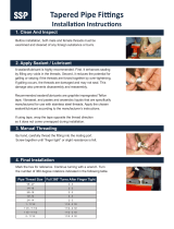
1. Inspect components to ensure that male and female port
threads and sealing surfaces are free of burrs, nicks,
scratches, or any foreign material.
2. Apply sealant/lubricant to male pipe threads if not pre-ap-
plied. For stainless steel ttings, the use of Parker Thread-
mate sealant/lubricant is strongly recommended. (Pre-
applied dry sealants are preferred over other sealants).
With any sealant, the rst one to two threads should be left
uncovered to avoid system contamination. If PTFE tape
is used it should be wrapped 1-1/2 to 2 turns in clockwise
direction when viewed from the pipe thread end.
Caution: More than two turns of tape may cause distortion
or cracking of the port.
3. Screw the connector into the port to the nger tight posi-
tion.
4. Wrench tighten the connector to the appropriate T.F.F.T.
values shown in Table R5, making sure that the tube end
of a shaped connector is aligned to receive the incoming
tube or hose assembly. Never back off (loosen) pipe
threaded connectors to achieve alignment.
5. If leakage persists after following the above steps, check
for damaged threads and total number of threads en-
gaged.
If threads on the tting are badly nicked or galled, replace the
tting. If port threads are damaged, re-tap, if possible, or replace
the component. If the port is cracked, replace the component.
Normally, the total number of tapered threads engaged should
be between 3-1/2 and 6. Any number outside of this range may
indicate either under or over tightening of the joint or out of tol-
erance threads. If the joint is under tightened, tighten it further
but no more than one full turn. If it is over tightened, check both
threads, and replace the part which has out-of-tolerance threads.
As a general rule, pipe ttings with tapered threads should not
be assembled to a specic torque because the torque required
for a reliable joint varies with thread quality, port and tting
materials, sealant used, and other factors. Where many of
these factors are well-controlled, such as particular jobs on an
assembly oor, a torque range that produces the desired results
may be determined by test and used in lieu of turns count for
proper joint assembly.
Table R5 – Assembly Turns From
Finger Tight (T.F.F.T) Values For
Steel, Stainless Steel and Brass Pipe
Fittings
Tapered Pipe
Thread Size
T.F.F.T.BSPT NPTF
1/8-28 1/8-27 2 - 3
1/4-19 1/4-18 2 - 3
3/8-19 3/8-18 2 - 3
1/2-14 1/2-14 2 - 3
3/4-14 3/4-14 2 - 3
1-11 1-11 1/2 1.5 - 2.5
1 1/4-11 1 1/4-11 1/2 1.5 - 2.5
1 1/2-11 1 1/2-11 1/2 1.5 - 2.5
2-11 2-11 1/2 1.5 - 2.5
Dimensions and pressures for reference only, subject to change.