Maxime R IN

Chors Maxime R IN User manual

  • I've reviewed the assembly instructions for the CHORS light fixtures, specifically the Maxime R IN 48.3114.xxx.xxx, 48.31XX.IXX.XXX, and 48.31XX.GXX.XXX models. The document covers mounting hole preparation, electrical wiring diagrams for different light sources, and step-by-step instructions. I'm ready to assist with any questions about these products.
  • What is the required mounting hole size?
    What type of power supply is needed?
    How to mount the light?
    What is max voltage for DC power supply?
Maxime R IN
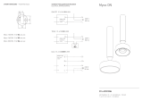
OTWORY MONTAŻOWE MOUNTING HOLES
1 X DC 350 MA, MAX. 60 VDC
MAX.3 X DC 350/700 MA, MAX. 60 VDC
1 X DC 350/700 MA
48.31XX.IXX.XXX
48.31XX.IXX.XXX
48.31XX.GXX.XXX
1 ŹRÓDŁO ŚWIATŁA
1 LIGHT SOURCE
MAKS. 3 ŹRÓDŁA ŚWIATŁA
MAX. 3 LIGHT SOURCES
MAKS. 1 ŹRÓDŁO ŚWIATŁA – SUNLIKE
MAX. 1 LIGHT SOURCE – SUNLIKE
CHORS
SCHEMATY PODŁĄCZEŃ ELEKTRYCZNYCH
ELECTRICAL WIRING DIAGRAMS
SOŁTYSOWICKA 19C | 51-168 WROCŁAW | POLAND
T: +48 71 323 14 00-01 | W: CHORS.PL
230V 50Hz
230V 50Hz
230V 50Hz
Ø 95 mm
min. 100 mm
Maxime R IN 48.3114.xxx.xxx
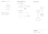
1. PLWyłącz zasilanie.
EN Turn o the power.
2. PLWytnij otwór montażowy
(wymiary otworów montażowych na drugiej stronie).
EN Cut the mounting hole
(dimensions of mounting holes on the other side of the page).
3. PLPodłącz zasilacz stałoprądowy 350 lub 700mA w zależności od źródła światła
(LED/SUNLIKE)
(schematy podłączeń elektrycznych na drugiej stronie).
EN Connect a 350 or 700mA DC power supply depending on the light source
(LED/SUNLIKE)
(electrical wiring diagrams on the other side of the page).
4. PLUnieś sprężyny.
EN Lift the springs.
5. PLWsuń lampę w otwór montażowy. Sprężyny wrócą do pierwotnej pozycji docisną
lampę do sufitu, przytrzymując ją.
EN Insert the lamp into the mounting hole. The springs will return to the original
position and press the lamp against the ceiling, holding it.
6. PLWłącz zasilanie.
EN Turn on the power.
1
6
3
350/700mA
4
4
5
+ -
INSTRUKCJA MONTAŻU • ASSEMBLY INSTRUCTIONS
2
/