1. PL • Wyłącz zasilanie.
EN • Turn o the power.
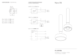
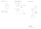
2. PL • Za pomocą śrub (A) i kołków rozporowych zamocuj do ściany uchwyt montażowy
(schemat otworów montażowych na drugiej stronie).
EN • Attach the profile to the wall with screws (A) and dowels
(mounting holes scheme on the other side of the page).
3. PL • Podłącz zasilanie 230V do zasilacza. Pamiętaj o uziemieniu
(schematy podłączeń elektrycznych na drugiej stronie).
EN • Connect the 230V power to the driver. Remember to ground
(electrical wiring diagrams on the other side of the page).
4a. PL • Nałóż dekiel na element montażowy.
EN • Place the lid on the mounting element.
4b. PL • Przykręć oprawę za pomocą ozdobnej nakrętki.
EN • Screw on the luminaire using the decorative nut.
5. PL • Włącz zasilanie.
EN • Turn on the power.
* PL • Załączony zestaw narzędzi jest przeznaczony do materiałów pełnych (cegła pełna,
drewno, beton, gazobeton) i powierzchni z płyt gipsowo-kartonowych. Kołek
rozporowy powinien zostać odpowiednio dopasowany do powierzchni montażowej.
Prawidłowe użycie kołka wpływa na bezpieczeństwo oraz wytrzymałość konstrukcji.
EN • The enclosed tool kit is designed for solid materials (solid brick, wood, concrete,
aerated concrete) and gypsum board surfaces. The dowel should be properly
matched to the mounting surface. Proper use of the dowel aects the safety and
strength of the structure.
2x 2x
1
5
~230V
50Hz
4a
4b
3
A
A
2
INSTRUKCJA MONTAŻU • ASSEMBLY INSTRUCTIONS
NARZĘDZIA • TOOLS


