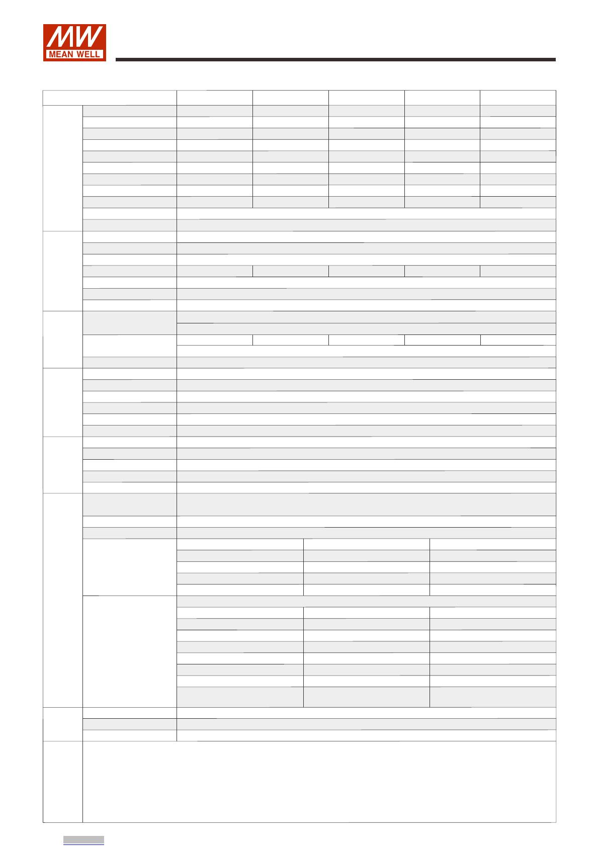
Mean Well RSP-1000 Series Owner's manual

Type
Owner's manual

Mean Well RSP-1000 Series is a 1000W power supply with active PFC function and up to 90% efficiency. It offers universal AC input, built-in fan cooling, and programmable output voltage. The RSP-1000 Series is suitable for factory control or automation, test and measurement instruments, laser-related machines, and RF applications, among others.

Mean Well RSP-1000 Series is a 1000W power supply with active PFC function and up to 90% efficiency. It offers universal AC input, built-in fan cooling, and programmable output voltage. The RSP-1000 Series is suitable for factory control or automation, test and measurement instruments, laser-related machines, and RF applications, among others.





 








 












1000W Power Supply with Single Output RSP-1000 series
File Name:RSP-1000-SPEC 2022-08-08







 





CNS14336-1 UL62368-1 GB4943.1
(except for 48V )
TPTC004 IEC62368-1BS EN/EN62368-1
Bauar
Sicherh eit
egel gem a
t gepru ft
od
be
www .
ID 2000000000
tuv.com
wac g
o s
User’s Manual
IS 13252
THOMAS SAMUEL
THOMAS SAMUEL


Downloaded from Arrow.com.
SPECIFICATION
MODEL
DC VOLTAGE
RATED CURRENT
CURRENT RANGE
RATED POWER
OUTPUT VOLTAGE ADJ. RANGE
LINE REGULATION
LOAD REGULATION
SETUP, RISE TIME
HOLD UP TIME (Typ.)
VOLTAGE RANGE Note.4
FREQUENCY RANGE
EFFICIENCY (Typ.)
INPUT
FUNCTION
INRUSH CURRENT (Typ.)
LEAKAGE CURRENT
OVER TEMPERATURE
WORKING TEMP.
DC OK SIGNAL
AUXILIARY POWER
REMOTE ON-OFF CONTROL
WORKING HUMIDITY
STORAGE TEMP., HUMIDITY
TEMP. COEFFICIENT
VIBRATION
MTBF
DIMENSIONOTHERS
NOTE
PACKING
OVERLOAD
OVER VOLTAGE
AC CURRENT (Typ.)
300ms, 50ms at full load
16ms/230VAC 16ms/115VAC at full load
90 ~ 264VAC 127 ~ 370VDC
47 ~ 63Hz
12A/115VAC 6A/230VAC
25A/115VAC 40A/230VAC
<2.0mA / 240VAC
105 ~ 125% rated output power
Protection type : Constant current limiting, recovers automatically after fault condition is removed
13.8 ~ 16.8V 17 ~ 20.5V 27.6 ~ 32.4V 31 ~ 36.5V 56.6 ~ 66.2V
Protection type : Shut down o/p voltage, re-power on to recover
Shut down o/p voltage, recovers automatically after temperature goes down
-20 ~ +60 (Refer to "Derating Curve")
Power ON : short Power OFF : open. Please refer to the Function Manual.
The TTL signal out, PSU turn on = 0 ~ 1V ; PSU turn off = 3.3 ~ 5.6V. Please refer to the Function Manual.
5V @ 0.5A (+5%, -8%)
20 ~ 90% RH non-condensing
-40 ~ +85, 10 ~ 95% RH non-condensing
±0.02%/ (0 ~ 50)
10 ~ 500Hz, 2G 10min./1cycle, 60min. each along X, Y, Z axes
939.4K hrs min. Telcordia SR-332 (Bellcore) ; 116.5K hrs min. MIL-HDBK-217F (25)
295*127*41mm (L*W*H)
1.95Kg; 6pcs/12.7Kg/1.15CUFT
83% 85% 88% 88% 90%
±0.5% ±0.5% ±0.5% ±0.5% ±0.5%
±0.5% ±0.5% ±0.5% ±0.5% ±0.5%
±1.0% ±1.0% ±1.0% ±1.0% ±1.0%
150mVp-p
10 ~ 13.5V
150mVp-p
13.5 ~ 16.5V
150mVp-p
20 ~ 26.4V
150mVp-p
24 ~ 30V
150mVp-p
43 ~ 55V
12V
60A
0 ~ 60A
720W
15V
50A
0 ~ 50A
750W
24V
40A
0 ~ 40A
960W
27V
37A
0 ~ 37A
999W
48V
21A
0 ~ 21A
1008W
RSP-1000-12 RSP-1000-15 RSP-1000-24 RSP-1000-27 RSP-1000-48




  
    
http://www.meanwell.com)
  ℃ ℃
 https://www.meanwell.com/serviceDisclaimer.aspx
POWER FACTOR (Typ.) 0.95/230VAC 0.98/115VAC at full load
SAFETY STANDARDS
UL62368-1, CSA C22.2 , TUV BS EN/EN62368-1, CCC GB4943.1, BSMI CNS14336-1, AS/NZS62368.1 No. 62368-1 ,
IS13252(Part1)/IEC60950-1, EAC TP TC 004 approved
RIPPLE & NOISE (max.) Note.2
VOLTAGE TOLERANCE Note.3
WITHSTAND VOLTAGE
ISOLATION RESISTANCE
I/P-O/P:3KVAC I/P-FG:2KVAC O/P-FG:0.5KVAC
I/P-O/P, I/P-FG, O/P-FG:100M Ohms / 500VDC / 25/ 70% RH
ENVIRONMENT
SAFETY &
EMC
(Note 5)
PROTECTION
1000W Power Supply with Single Output RSP-1000 series
File Name:RSP-1000-SPEC 2022-08-08
Parameter
Parameter
ESD
Radiated
EFT / Burst
Surge
Conducted
Magnetic Field
Voltage Dips and Interruptions
Conducted
Radiated
Harmonic Current
Voltage Flicker
Standard
Standard
BS EN/EN55032 (CISPR32)
BS EN/EN61000-3-2
BS EN/EN61000-3-3
BS EN/EN61000-4-2
BS EN/EN61000-4-3
BS EN/EN61000-4-4
BS EN/EN61000-4-5
BS EN/EN61000-4-6
BS EN/EN61000-4-8
BS EN/EN61000-4-11
Test Level / Note
Test Level / Note
Level 3, 8KV air ; Level 2, 4KV contact
Level 3
Level 3
Level 3
Level 4
>95% dip 0.5 periods, 30% dip 25 peniods,
>95% interruptions 250 periods
Class B
Class A
-----
-----
EMC IMMUNITY
EMC EMISSION
Adjustment of output voltage is allowable to 40 ~ 110% of nominal output voltage. Please refer to the Function Manual.
OUTPUT VOLTAGE PROGRAMMABLE(PV)
BS EN/EN55035, BS EN/EN61000-6-2, CCC GB17625.1, GB/T9254, BSMI CNS13438
CURRENT SHARING Up to 4000W or (3+1) units. Please refer to the Function Manual.
REMOTE SENSE Compensate voltage drop on the load wiring up to 0.5V. Please refer to the Function Manual.
Level 4, 4KV/Line-Earth ; Level 3, 2KV/Line-Line
Downloaded from Arrow.com.Downloaded from Arrow.com.
60
65
70
75
80
85
90
95
10% 20% 30% 40% 50% 60% 70% 80% 90% 100%
Static Characteristics
LOAD (%)LOAD (%)
INPUT VOLTAGE (VAC) 60Hz
90 95 100 115 264
90
100
80
70
60
50
40
Block Diagram
PFC fosc : 110KHz
PWM fosc : 90KHz
&
PFC
FILTER
&
RECTIFIERS AUX POWER(5V/0.5A)
PFC
CONTROL
O.L.P.
AUX GND
SHARE
CURRENT CURRENT
V_TRIM
DC OK
SHARE
O.V.P.
REMOTE ON-OFF
RECTIFIERS
CONTROL
ON/OFF
FAN
LIMITING
ACTIVE
CURRENT
INRUSH
CONTROL
I/P -V
+V
RECTIFIERS
&
FILTER
SWITCHING
POWER
RECTIFIERS
FILTER
EMI
PWM
-S
+S
CIRCUIT
DETECTION
POWER
AUX
1000W Power Supply with Single Output RSP-1000 series
File Name:RSP-1000-SPEC 2022-08-08
Efficiency vs Load (48V Model)
The curve above is measured at 230VAC.
MODEL 12V
720W
648W
750W
675W
960W
864W
999W
899.1W
1008W
907.2W
60A
54A
50A
45A
40A
36A
37A
33.3A
21A
18.9A
100~264VAC
90VAC
15V 24V 27V 48V
INPUT
EFFICIENCY (%)
LOAD
Derating Curve
AMBIENT TEMPERATURE ()
20
40
60
80
100
-20 0 10 20 30 40 50 60 70 (HORIZONTAL)
Downloaded from Arrow.com.Downloaded from Arrow.com.Downloaded from Arrow.com.
Function Manual
1000W Power Supply with Single Output RSP-100 0 s e r ies
File Name:RSP-1000-SPEC 2022-08-08
1.Remote Sense
The Remote Sense compensates voltage drop on the load wiring up to 0.5V
The +S signal should be connected to the positive terminal of the load whereas -S signal to the negative terminal.
This configuration is based on the assumption the Output Voltage Programming is not activated and power supply is ON.
TB1
-V+V CN50
1 11
2 12
PIN8 Vco
PIN10 Vca
PIN6 REMOTE ON-OFF
LOAD
-V
+V
PIN1 +S
PIN2 -S
Sense lines should be twisted in pairs to minimize noise pick-up.
Fig 1.1
Between Remote ON-OFF (pin6) and -S(pin2)
Switch Short
Switch Open
ON
Power Supply Status
OFF
2.Remote ON-OFF Control
When multiple power supplies need to turn ON/OFF simultaneously by Remote ON-OFF control, -S & -V, as well as +S & +V, on each power supply
should be connected.
TB1
-V+V CN50
Fig 2.1
Fig 3.1
LOAD
-
+
1 11
2 12
Switch
PIN2 -S
PIN6 REMOTE ON-OFF
PIN10 Vca
PIN8 Vco
3.DC_OK signal
"DC_OK" is an open collector signal. It indicates the output status of the power supply. It can operate in two ways : One is sinking current from external
TTL signal ; the other is sending out a TTL voltage signal.
Sinking current from external TTL signal: The maximum sink current is 10mA and the maximum external voltage is 5.6V.
Sending out TTL voltage signal :
Between DC- OK(pin5) and GND(pin11&12)
0 ~ 1V
3.3 ~ 5.6V
Output Status
ON
OFF
TB1
-V+V CN50
1 11
2 12
PIN2 -S
PIN5 DC_OK PIN12 GND
PIN6 REMOTE ON-OFF
PIN10 Vca
PIN8 Vco
The power supply can be turned ON-OFF indivicluaaly or along with other units by using the “Remote ON-OFF” function.
The power supply is shipped, by factory default, with Remote ON-OFF(pin6) and -S(pin2) shorted by connector.
Downloaded from Arrow.com.Downloaded from Arrow.com.Downloaded from Arrow.com.Downloaded from Arrow.com.
1000W Power Supply with Single Output RS P- 1 0 0 0 serie s
TB1
TB1
-V
-V
+V
+V
CN50
CN50
1 11
2 12
1 11
2 12
PIN10 Vca
PIN10 Vca
PIN9 Vci
PIN9 Vci
PIN4 AUX
PIN4 AUX
PIN6 REMOTE ON-OFF
PIN6 REMOTE ON-OFF
PIN1 +S
PIN1 +S
PIN3 AUXG
PIN3 AUXG
PIN2 -S
PIN2 -S
Fig 4.2
Fig 4.3
Fig 4.1.1 Fig 4.2.1 Fig 4.3.1
(2)Applying EXTERANL RESISTANCE as shown in Fig4.2 & Fig 4.3
(A) Output voltage goes down
EXTERNAL RESISTANCE (Ω)
390 560
820
1K2 2K2 4K7 open R1, 1/8W(Typ.)
80
90
100
Vout
70
60
Non-Linear
50
40
R1
R2
OUTPUT VOLTAGE (%)
+S & +V and -S & -V also need to be connected on CN50.
(B)Output voltage goes up
EXTERNAL RESISTANCE (Ω)
open
18K 7K5 R2, 1/8W(Typ.)
110
Vout
OVP 120%(Typ.)
Non-Linear
105
100
OUTPUT VOLTAGE (%)
Caution: By factory default, the Output Voltage Programming is not activated, and Vco (pin8) and Vca(pin10) are shorted by connector. Whenever this
function is not needed to activate, as assumed in other sections’ diagrams, please keep Vco(pin8) and Vca(pin10) shorted ; other wise, the
power supply will have no output.
EXTERNAL VOLTAGE (VDC)
1 2 3 4 5 6 Vci(Referenced to -S)
100
120
Vout OVP 120%(Typ.)
Non-Linear
80
60
40
20
OUTPUT VOLTAGE (%)
(1)Applying EXTERNAL VOLTAGE between "Vci"(pin9) and "-S"(pin2) as shown in Fig4.1
In addition to the adjustment via the built-in potentiometer, the output voltage can be trimmed to 40~110% of the nominal voltage by applying
+S & +V and -S & -V also need to be connected on CN50
either an EXTERNAL VOLTAGE or an EXTERNAL RESISTANCE.
4. Output Voltage Programming (or, PV / remote voltage programming / remote adjust / margin programming / dynamic voltage trim)
TB1
-V+V CN50
1 11
2 12
EXTERNAL VOLTAGE (DC)
PIN9 Vci
PIN6 REMOTE ON-OFF
PIN1 +S
PIN2 -S
Fig 4.1
R1
R2
+S
1
1
+S
-S
2
2
-S
AUXG
AUXG
AUX
AUX
DC_OK
REMOTE
ON-OFF
REMOTE
ON-OFF
DC_OK
CS
CS
CN50
CN50
Vco
Vco
Vci
Vci
Vca
Vca
GND
11
11
GND
GND
12
12
GND
LOAD
LOAD
+V
+V
-V
-V
External Voltage
+S
1
-S
LOAD
+V
-V
2
AUXG
AUX
DC_OK
ON/OFF
CS
CN50
Vco
Vci
Vca
GND
11
GND
12
File Name:RSP-1000-SPEC 2022-08-08
Downloaded from Arrow.com.Downloaded from Arrow.com.Downloaded from Arrow.com.Downloaded from Arrow.com.Downloaded from Arrow.com.
5.Current Sharing with Remote Sense
+S+S+S+S
-S-S-S-S
AUXGAUXGAUXGAUXG
AUXAUXAUXAUX
DC_OKDC_OKDC_OKDC_OK
ON/OFFON/OFFON/OFFON/OFF
CSCSCSCS
VcoVcoVcoVco
VciVciVciVci
VcaVcaVcaVca
GNDGNDGNDGND
GNDGNDGNDGND
PSU PSU PSU PSU
-V Sense lines should
be twisted in pairs
+V
LOAD
1111 11111111 CN50CN50CN50CN50
Fig 5.1
CS(pin7)
+S(pin1)
-S(pin2)
2222 12121212
TB1 TB1 TB1 TB1
-V -V -V -V
+V +V +V +V
CN50 CN50 CN50 CN50
1 11
2 12
1 11
2 12
1 11
2 12
1 11
2 12
1000W Power Supply with Single Output RSP-1000 serie s
File Name:RSP-1000-SPEC 2022-08-08
Difference of output voltages among parallel units should be less than 0.2V.
RSP-1000 has the built-in active current sharing function and can be connected in parallel, up to 4 units, to provide higher output power as exhibited below :
The total output current must not exceed the value determined by the following equation:
When the total output current is less than 5% of the total rated current, or say (5% of Rated current per unit)×(Number of unit)
the current shared among units may not be fully balanced.
Maximum output current at parallel operation=(Rated current per unit)×(Number of unit)×0.9
+S,-S and CS are connected mutually in parallel.
The power supplies should be paralleled using short and large diameter wiring and then connected to the load.
Downloaded from Arrow.com.Downloaded from Arrow.com.Downloaded from Arrow.com.Downloaded from Arrow.com.Downloaded from Arrow.com.Downloaded from Arrow.com.
Mounting Screw
Mounting Surface Chassis of RSP-1000
1000W Power Supply with Single Output RSP-1000 serie s
File Name:RSP-1000-SPEC 2022-08-08
Mechanical Specification Case No. 952B Unit:mm
1
11
TB1
3
2
1
7
+V
-V
20.5
Air flow
direction
41
127
18.5
3-M4 L=4
2-M5
90
10
6
277.7
25.4 7.8
21 34.5
59
295
277.7
25.47.8
6
20.5
CN50
2
12
SVR51
3-M4 L=6
3-M4 L=6
Pin No. Function Description
1
4
5
7
8
10
11,12
2
3
6
9
+S
5V-AUX
DC_OK
CS
Vco
Vca
GND
-S
G-AUX
Remote
ON-OFF
Vci
Auxiliary voltage output, 4.6~5.25V, referenced to pin 3(G-AUX).
The maximum load current is 0.5A. This output has the built-in oring diodes and is not controlled by the "remote ON/OFF control".
Open collector signal, referenced to pin11,12(GND).
Low when PSU turns on. The maximum sink current is 10mA and the maximum external voltage is 5.6V.
Current sharing signal. When units are connected in parallel, the CS pins of the units should be connected to allow current balance
between units.
Short connecting between Vco (pin8) and Vca (pin10) if output voltage programming function is not activated.
Connect to external resistor (1/8W) for output voltage programming.
These pins connect to the negative terminal (-V). Return for DC_OK Signal output.
Turns the output on and off by electrical or dry contact between pin 6 (Remote ON-OFF) and pin 2 (-S). Short: Power ON, Open: Power OFF.
Connect to external DC voltage source for output voltage programming, referenced to pin 2 (-S).
Negative sensing for remote sense.
Positive sensing for remote sense.
Auxiliary voltage output ground.
The signal return is isolated from the output terminals (+V & -V).
1
2
11
12
Control Pin No. Assignment : HRS DF11-12DP-2DS or equivalent(CN50)
Mating Housing
Terminal
HRS DF11-12DS or equivalent
HRS DF11-**SC or equivalent
1
1
2
2
2
1
1
1
1
Mounting Instruction
Hole No. Recommended Screw Size MAX. Penetration Depth LRecommended mounting torque
1
2
6mm
4mm
M4
M4
7~11Kgf-cm
7~11Kgf-cm
Downloaded from Arrow.com.Downloaded from Arrow.com.Downloaded from Arrow.com.Downloaded from Arrow.com.Downloaded from Arrow.com.Downloaded from Arrow.com.Downloaded from Arrow.com.
Installation Manual
Please refer to : http://www.meanwell.com/manual.html
DC Output Terminal Pin No. Assignment
Assignment Diagram Maximum mounting torque
10Kgf-cm
+V, -V
1000W Power Supply with Single Output RSP-1000 serie s
File Name:RSP-1000-SPEC 2022-08-08
AC Input Terminal Pin No. Assignment
Pin No.
1
3
2
Assignment Diagram Maximum mounting torque
18Kgf-cm
AC/N
AC/L
FG
Downloaded from Arrow.com.Downloaded from Arrow.com.Downloaded from Arrow.com.Downloaded from Arrow.com.Downloaded from Arrow.com.Downloaded from Arrow.com.Downloaded from Arrow.com.Downloaded from Arrow.com.
  • Page 1 1
  • Page 2 2
  • Page 3 3
  • Page 4 4
  • Page 5 5
  • Page 6 6
  • Page 7 7
  • Page 8 8

Mean Well RSP-1000 Series Owner's manual

Type
Owner's manual

Mean Well RSP-1000 Series is a 1000W power supply with active PFC function and up to 90% efficiency. It offers universal AC input, built-in fan cooling, and programmable output voltage. The RSP-1000 Series is suitable for factory control or automation, test and measurement instruments, laser-related machines, and RF applications, among others.

Ask a question and I''ll find the answer in the document

Finding information in a document is now easier with AI