Vista 1142 User manual

Type
User manual

Vista 1142 is an architectural series inground and well light, suitable for both soil and concrete installations. It features a wet location listing, making it ideal for outdoor use. The fixture is designed to prevent overheating and ensure efficient operation with a clean lens free of dirt, dust, leaves, and mineral deposits. It can accommodate up to four No. 12 AWG conductors (plus ground) rated for 90 degrees Celsius and supports through wiring.

Vista 1142 is an architectural series inground and well light, suitable for both soil and concrete installations. It features a wet location listing, making it ideal for outdoor use. The fixture is designed to prevent overheating and ensure efficient operation with a clean lens free of dirt, dust, leaves, and mineral deposits. It can accommodate up to four No. 12 AWG conductors (plus ground) rated for 90 degrees Celsius and supports through wiring.

INSTALLATION INSTRUCTIONS
Inground & Well Lights
Architectural Series
1142
1625 Surveyor Avenue • Simi Valley, CA 93063 • (805) 527-0987 • (800) 766-VISTA (8478)
FAX: (888) 670-VISTA (8478) • [email protected] • www.vistapro.com
Vista Professional Outdoor Lighting reserves the right to modify the design and/or construction of the fixture shown without further notification.
INGRADE SOIL INSTALLATION:
IMPORTANT NOTE: Temporary cover plate and vinyl label must remain in place during Rough-In Section Housing installation.
PRECAUTION: Adequate drainage must be provided during installation. It is recommended the luminaire be surrounded by 3” to 4” of pea gravel
along the sides and a minimum of 6” of pea gravel at the bottom beneath the luminaire housing. Top of luminaire must be above grade so rain and
irrigation water will not accumulate for long periods of time.
1.To prevent electrical shock, turn main power off at circuit breaker.
2.Dig hole approximately 12” wide to a depth suitable to make top of temporary cover plate 3/8 ” above grade. Pea gravel is required for seating the
Rough-in section housing and providing necessary drainage.
3.Connect conduit to housing. UL listed outdoor rated conduit is recommended for in and out connections to ensure water tightness of splices.
4.Plug any unused NPT holes with closure plugs (provided).
5.Position fixture within the hole and back fill with pea gravel. Only the uppermost layer, 3” maximum, should be soil or organic mulch.
6.To pull supply conductor wiring, first remove and retain the temporary cover plate by using a screwdriver.
7.Remove and retain junction box cover and cover screws.
8.Pull electrical supply wires (line in) through conduit and junction box. For through branch wiring, pull wires upward making a 6” loop above the top
rim of the junction box.
9.Stuff the wire loop back into the junction box and reinstall the junction box cover using the cover screws.
10.Reinstall the temporary cover plate with vinyl label by snapping the plate into the Rough-In Section.
IMPORTANT NOTE:
Luminaire must be installed and grounded in accordance with the National Electrical Code (NEC) and local codes.
All conduit entries must be sealed from moisture. Use appropriate sealing material on conduit fittings and conduit closure plugs.
Luminaire is wet location listed and suitable for in-grade applications.
Suitable for all types of construction including poured concrete construction and in soil applications. SOIL INSTALLATIONS NOT SUITABLE FOR
DRIVE OVER LOADING OF FIXTURE.
Suitable for through wiring: Max. of (4) No. 12 AWG conductors (plus ground) rated for 90 °C.
WARNING: Debris must be kept clear from top and interior of in-grade fixtures. Excessive heat could occur that may create a fire hazard and/or harm
the fixture components. Specific attention must be made to never install in-grade fixtures in mulch, wood chips or other potentially ignitable materials.
Failure to do so will void the warranty and may result in serious injury and/or damage to the fixture and/or property.
SAFETY WARNING: Luminaire can become very hot depending on the lamp wattage used. Lens and housing around the lamp can become hot enough
to blister hands. Particular care should be taken not to locate luminaires where small children can reach them if high wattage lamps are used.
MAINTENANCE: To assure proper operation and efficiency and to prevent luminaires overheating, lens must be kept clean and free of dirt, dust, leaves,
trash and mineral deposit from water. A regular scheduled maintenance program is recommended.
NOTE: Save these instructions for future reference.
PEA GRAVEL
(BY OTHERS)
3/8" 4-5/8"
5-1/16"
7-3/8"
SOIL INSTALLATION
INSTALLATION INSTRUCTIONS
Inground & Well Lights
Architectural Series
1142
1625 Surveyor Avenue • Simi Valley, CA 93063 • (805) 527-0987 • (800) 766-VISTA (8478)
FAX: (888) 670-VISTA (8478) • [email protected] • www.vistapro.com
Vista Professional Outdoor Lighting reserves the right to modify the design and/or construction of the fixture shown without further notification.
CONCRETE POUR INSTALLATION:
IMPORTANT NOTE: Temporary cover plate and vinyl label must remain in place during Rough-In Section housing installation.
PRECAUTION: Adequate drainage must be provided during installation. It is recommended the luminaire be surrounded by 3” to 4” of pea gravel along
the sides and a minimum of 6” of pea gravel at the bottom beneath the luminaire housing. Top of luminaire must be FLUSH with finish grade.
1.To prevent electrical shock, turn main power off at circuit breaker.
2.Dig a hole approximately 12” wide to a depth suitable to make top of temporary cover plate FLUSH with finish grade. Pea gravel is required for seating
the Rough-In section housing and providing necessary drainage.
3.Connect conduit to Junction Box. UL listed outdoor rated conduit is recommended for in and out connections to ensure water tightness of splices.
4.Plug any unused NPT holes with closure plugs (provided).
5.Position Rough-In Section within the hole and back fill with pea gravel. Only the uppermost layer, 6” maximum, should be concrete pour.
6.To keep Rough-In Section housing from floating during concrete pour, the Rebar Mount Bracket (RMB) kit should be used to affix housing to a wire/
rebar grid using standard masonry methods.
7.To pull supply conductor wiring, first remove and retain the temporary cover plate using a screwdriver in the retaining clip slot.
8.Remove and retain junction box cover and cover screws.
9.Pull electrical supply wires (line in) through conduit and junction box. For through branch wiring, pull wires upward making a 6” loop above the top
rim of the junction box.
10.Stuff the wire loop back into the junction box and reinstall the junction box cover using the cover screws.
11.Reinstall the temporary cover plate with vinyl label by snapping the plate into the Rough-In Section.
12.Pour concrete at least 3” thick. Trowel concrete so that it is even with vinyl label. Allow concrete to cure.
5-1/16"
7-3/8"
4-5/8"
PEA GRAVEL
(BY OTHERS)
CONCRETE
(BY OTHERS)
CONCRETE INSTALLATION
INSTALLATION INSTRUCTIONS
Inground & Well Lights
Architectural Series
1142
1625 Surveyor Avenue • Simi Valley, CA 93063 • (805) 527-0987 • (800) 766-VISTA (8478)
FAX: (888) 670-VISTA (8478) • [email protected] • www.vistapro.com
Vista Professional Outdoor Lighting reserves the right to modify the design and/or construction of the fixture shown without further notification.
INSTRUCTIONS FOR SEALING WIRING COMPARTMENT
Note: Failure to properly wire and encapsulate wiring compartment
will void product warranty.
8. After properly wiring the Supply and Load Conductors, position the
Silicone filled Wire Nuts at the bottom of the Junction Box.
9. Use Duct Seal around the opening of the conduit entry and the Supply
Wires to seal off the conduit opening.
10. Fill the inside of the Junction Box to cover the Duct Seal but no more
than to the top of the inside hub with re-enterable potting sealant.
DO NOT OVERFILL OR UNDERFILL!
11. To properly mix the re-enterable potting sealant, remove the pouch
from the protective cover. Grasp both sides of the sealant pouch, breaking
the internal barrier between parts A&B.
12. Mix the sealant by kneading the two sides back and forth until
thoroughly
mixed.
13. Cut a corner off of the pouch and pour into the inside of the Junction
Box,
completely covering the Silicon filled wire nuts. Allow the sealant to dry for
approximately 20 minutes or until compound has gelled.
14. Re-install the Junction box Cover, making sure it is fully tightened until
the lid bottoms out on the inside of the RIS.
15. Position the LINEAR LED Module into the RIS and snap in place.
16. Supply power to the luminaire and check for proper operation.
1142 10.19.21
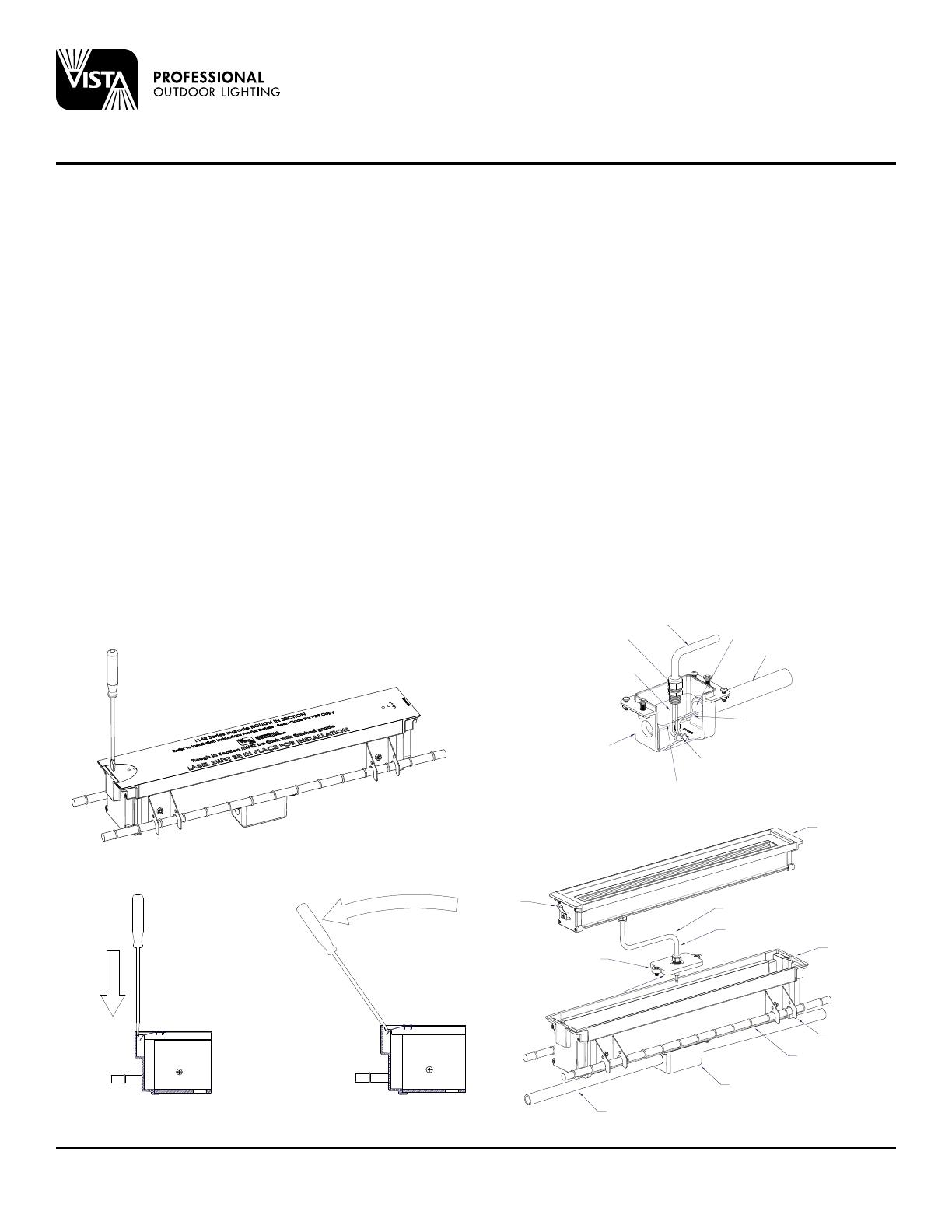
LINEAR LED MODULE AND J-BOX COVER INSTALLATION:
1.To prevent electrical shock, turn main power off at the circuit breaker.
2.Remove temporary cover plate with vinyl label. Recycle or discard cover
plate.
3.Remove and retain Junction Box Cover and Cover Screws.
4.Route the free end of the LINEAR LED Module Load Conductor Cable
through the top side of J-Box Cord Seal and out the back side of the
J-Box Cover.
5.Using the appropriate size open end wrench or Crescent wrench, firmly
tighten the top nut of the J-Box Cord Seal such that the outer jacket of the
LINEAR LED Module Load Conductor Cable extends past the back side of
the J-Box Cover a distance of 1” to 2”. Set the LINEAR LED Module with
the attached J-Box Cover aside.
6.Pull the Supply Conductor wire loop out of the J-Box, cut at center and
strip the leads.
7.Using the Silicone Filled Wire Nuts (provided), connect the Supply
Conductors in the Junction-Box to the Load Conductors of the LINEAR
LED Module noting the following polarity:
Supply (+) to Load (Black)
Supply (-) to Load (White)
Supply (Ground) to Load (Green)
If 0-10V dimming is used:
Dimming Supply (+) to Dimming Load (Red)
Dimming Supply (-) to Dimming Load (Orange)
JUNCTION
BOX COVER
COVER
SCREWS
JUNCTION BOX
CORD SEAL ROUGH-IN
SECTION
REBAR
BRACKET
JUNCTION
BOX
LINEAR OPTIC
MODULE
LOAD CONDUCTOR
CABLE
RETAINING
CLIPS
SUPPLY
CONDUIT
REBAR
TEMP COVER/OPTIC MODULE ACCESS
EXPLODED VIEW
CABLE GRIP
LOAD
CONDUCTORS
JUNCTION
BOX
RE-ENTERABLE
POTTING SEALANT
SILICON FILLED
WIRE NUTS
SUPPLY
CONDUCTORS
CONDUIT
DUCT SEAL
LOAD
CONDUCTOR
CABLE
  • Page 1 1
  • Page 2 2
  • Page 3 3

Vista 1142 User manual

Type
User manual

Vista 1142 is an architectural series inground and well light, suitable for both soil and concrete installations. It features a wet location listing, making it ideal for outdoor use. The fixture is designed to prevent overheating and ensure efficient operation with a clean lens free of dirt, dust, leaves, and mineral deposits. It can accommodate up to four No. 12 AWG conductors (plus ground) rated for 90 degrees Celsius and supports through wiring.

Ask a question and I''ll find the answer in the document

Finding information in a document is now easier with AI