10
DRIVE
• Powered by a 12 V motor with integral case hardened steel gear reduction to 90 rpm. Generates 310 in. lb. of torque at 12
V. Motor temperature range -30 °F to +160 °F.
• Gate velocity: 1 ft/s.
POWER
• The PRO SL-2000 system is powered by a 12 Vdc, 7.0 Ah, sealed, rechargeable battery.
• Battery charge for PRO SL-2000 is maintained by a 18 Vac (40 VA) transformer rectified to 14.5 Vdc through the GTO
Control Board. Two (2) blade-style control board fuses rated for 20 A.
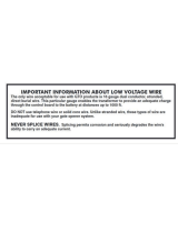
IMPORTANT:
The transformer should not be connected directly to any battery. Transformer must be connected to the control
board with a minimum of 16 gauge, multi-stranded, dual conductor, direct burial low voltage wire. Do not replace fuses with
higher ampere rated fuses; doing so will void the warranty and may damage the control board.
•
Solar Panel Charger can only be used on the SL-2000 if the optional 24 Amp hour battery kit is used
(see Accessory Catalog on
page 41).
Battery charge maintained by GTO Solar Panel Charger: float voltage 14.5 Vdc output from a 19
3
/
8
” x 15
1
/
4
”
silicon alloy panel. Generates minimum of 10 W at 600 mA. Gated diode on the control board prevents battery discharge.
CONTROL
• GTO microprocessor controlled board with temperature compensated circuits. Auto-memorization of digital transmitter
code. Charging regulated by circuit on control board. “Sleep draw” is 40 mA; “active draw” is 5 to 13 A.
• GTO remote-mounted RF receiver tuned to 318 MHz.
• Limit controls are mechanical. Normally open contact.
• Adjustable auto-close timer (OFF to 120 s), inertia, and obstruction sensitivity using three (3)
potentiometers.
• Power terminal block accommodates a transformer and solar panels.
• Operator terminal blocks accommodate safety edges and photoelectric sensors for opening and closing modes.
• Fully compatible accessory terminal block provides connections for safety loops, wands, intercoms, card readers, phone
systems, etc.
• DIP switches simplify setup of gate operator.
• audio entrapment alarm sounds if unit obstructs twice while opening or closing.
OPERATIONAL CAPACITY
• The GTO/PRO SL-2000 and GTO/PRO SL-2000B will handle gates weighing up to 1000 lb. (453.4 kg) and up to 30 ft.
(9.14 m) in length (per leaf) if the proper installation procedures have been followed.
Note that ball bearing rollers
and covers should be used on all gates.
• The GTO/PRO SL-2000 series operators are capable of high volume cycling; however, the total cycles per day will depend
on the motor current and efficiency of the gate installation (see chart below). For questions relating to specific applications
and for information regarding cycling duty when charged by solar panels, call the GTO Service Department at (800) 543-
1236.
GTO PRO SL-2000 SERIES TECHNICAL SPECIFICATIONS
Rollers should be lubricated at least four times per year.
SPECIFICATIONS SUBJECT TO CHANGE WITHOUT NOTICE.
Housing Dimensions: Height: 18” Width: 21
1
/2” Depth: 11”
Shipping Weight: Approximately 90 lb.
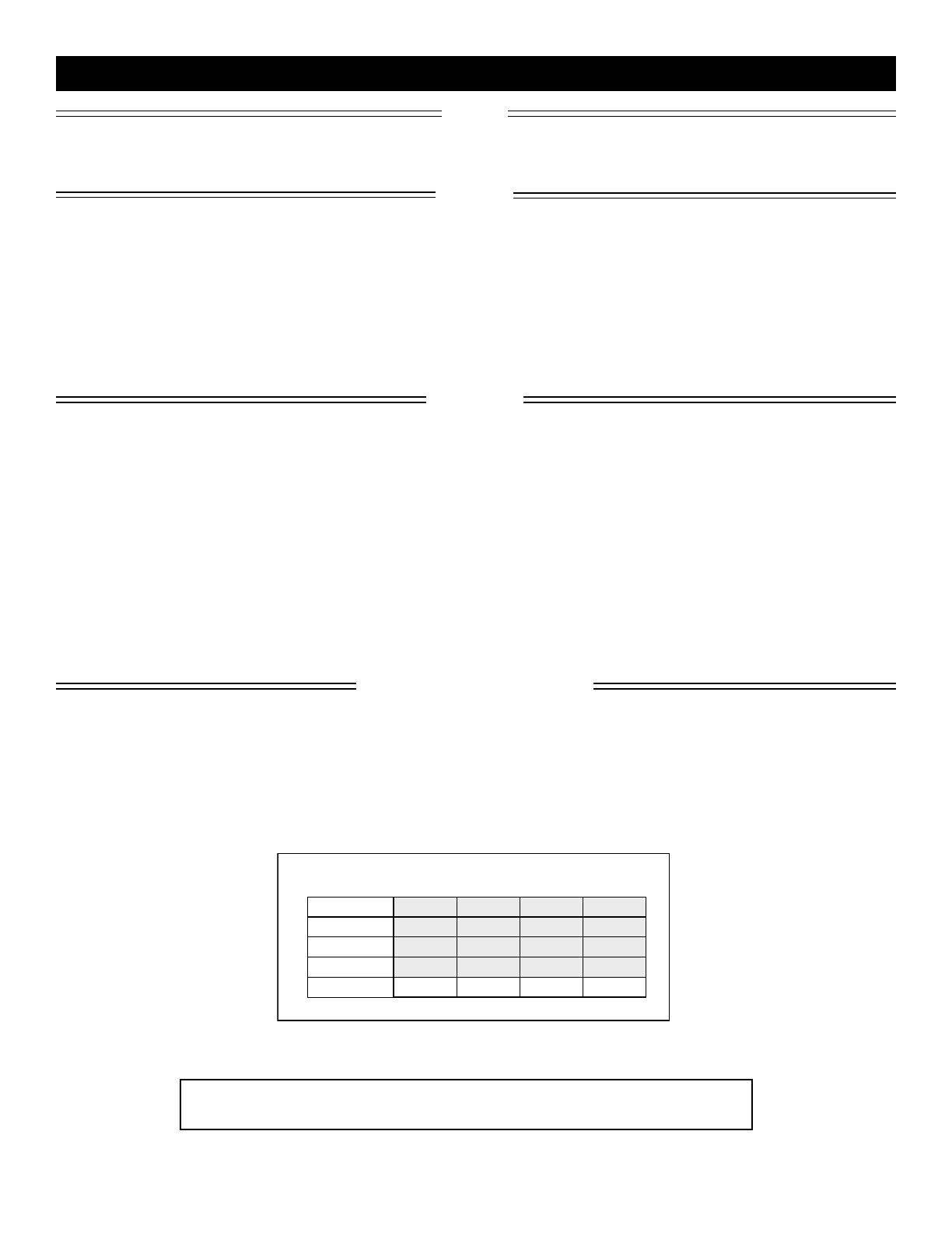
Cycles shown are for single gate, dual gates will get approximately half as many cycles.
Gate Weight
Gate Opening
Gate Capacity Chart for SL-2000 Series
(estimated number of cycles based on use with a transformer)
20 ft.
16 ft.
12 ft.
8 ft.
80
100
120
140
400 lb.
70
90
110
130
600 lb.
60
80
100
120
800 lb.
50
70
90
110
1000 lb.