Page is loading ...

Composite-ARF Extra 330L (2.6m span)
Instruction Manual
Composite-ARF Extra 330L, 2.6 m
TAVS Technology
version 2.0

Composite-ARF Extra 330L (2.6m span)
Sheet 1
P15P14P13
P9 P12P10 P11
P8P7P6P5
P4P3P2P1
P16
VERSION 2.0 Mike C (29 March 2004) Mac

Composite-ARF Extra 330L (2.6m span)
Sheet 2
P31P29
P25 P28P26 P27
P24P23P22P21
P20P19P18P17
P32
VERSION 2.0 Mike C (29 March 2004) Mac
P30

Composite-ARF Extra 330L (2.6m span)
Sheet 3
P47P46P45
P41 P44P42 P43
P40P39P38P37
P36P35P34
P33
P48
VERSION 2.0 Mike C (29 March 2004) Mac
18mm

Composite-ARF Extra 330L (2.6m span)
Sheet 4
P55P54
3
P53
P52P51P50P49
P57
VERSION 2.0 Mike C (12 March 2004) Mac
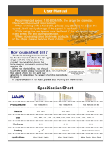
AILERON THROWS
low rate: 50mm down
high rate: 60mm down
high rate: 70mm up
low rate: 45mm up
RUDDER THROWS
high rate: 170mm (max.)
low rate: 125mm
low rate: 125mm
high rate: 170mm (max.)
ELEVATOR THROWS
high rate: 80mm (max.)
low rate: 35mm
low rate: 35mm
high rate: 80mm (max.)
2 - 3° depending on propeller
SIDETHRUST
C of G range: 90 -100mm
from Leading Edge at Wing Tip.
CENTRE of GRAVITY
P56

Instructions for Extra 330L IMAC-Airplane
Thank you very much for purchasing our Composite-ARF Extra 330L all composite aircraft, made
with the revolutionary Total Area Vacuum Sandwich (TAVS) technology
Before you get started building and setting-up your aircraft, please make sure you have read this
instruction manual several times, and understood it. If you have any questions, please don’t
hesitate to contact us. Below are the contact details:
Email: [email protected]
Telephone: Phone your C-ARF Rep!!! He will be there for you.
Website: http://www.composite-arf.com
This instruction manual aims to do 3 things:
1) Show you how to build your aircraft accurately and properly.
2) To explain about your fully-composite aircraft, and how to handle and maintain it.
3) How to set up and trim your finished IMAC type aircraft perfectly to give you the most enjoy-
ment from it.
Below are a few of the TOC pilots who helped to design and modify our 3m Extra 330S to the
championship-winning standard it is now at. And your 2.6m span Extra 330L is based on the
design of that plane and the experience of these experts.
Composite-ARF Extra 330L (2.6m span)
2
Jason Shulman
Sebastiano Silvestri
Ivan Kristensen
Mike McConville
Composite-ARF
would like to thank all of
these 4 very experienced
pilots for their co-operation and
help, which has made this 330 Extra
aeroplane as good as it is today.
Of course all four of them are also Rep’s for
C-ARF, and if you want to ask them any questions
you can email them (see our website for links) directly,
or email your questions to us at ‘feedback@composite-
arf.com’ and we will forward your comments to them.
We are sure that they will answer you right away.

Liability Exclusion and Damages
You have acquired a kit, which can be assembled into a fully working R/C model when fitted out
with suitable accessories, as described in the instruction manual with the kit.
However, as manufacturers, we at Composite-ARF are not in a position to influence the way you
build and operate your model, and we have no control over the methods you use to install,
operate and maintain the radio control system components. For this reason we are obliged to
deny all liability for loss, damage or costs which are incurred due to the incompetent or incorrect
application and operation of our products, or which are connected with such operation in any
way. Unless otherwise prescribed by binding law, the obligation of the Composite-ARF compa-
ny to pay compensation is excluded, regardless of the legal argument employed.
This applies to personal injury, death, damage to buildings, loss of turnover and business,
interruption of business or other direct and indirect consequent damages. In all circumstances
our total liability is limited to the amount which you actually paid for this model.
BY OPERATING THIS MODEL YOU ASSUME FULL RESPONSIBILITY FOR YOUR ACTIONS.
It is important to understand that Composite-ARF Co., Ltd, is unable to monitor whether you
follow the instructions contained in this instruction manual regarding the construction, operation
and maintenance of the aircraft, nor whether you install and use the radio control system
correctly. For this reason we at Composite-ARF are unable to guarantee or provide a
contractual agreement with any individual or company that the model you have made will
function correctly and safely. You, as operator of the model, must rely upon your own expertise
and judgement in acquiring and operating this model.
Supplementary Safety Notes
Pre-flight checking:
Before every session check that all the model’s working systems function correctly, and be sure
to carry out a range check.
The first time you fly any new model aircraft we strongly recommend that you enlist the help of
an experienced modeller to help you check the model and offer advice while you are flying. He
should be capable of detecting potential weak points and errors.
Be certain to keep to the recommended CG position and control surface travels. If adjustments
are required, carry them out before operating the model.
Be aware of any instructions and warnings of other manufacturers, whose product(s) you use to
fly this particular aircraft, especially engines and radio equipment.
Please don’t ignore our warnings, or those provided by other manufacturers. They refer to things
and processes which, if ignored, could result in permanent damage or fatal injury.
Composite-ARF Extra 330L (2.6m span)
3

Composite-ARF Extra 330L (2.6m span)
4
Attention !
This IMAC-Aircraft is a high-end product and can create an enormous risk for both pilot and
spectators, if not handled with care, and used according to the instructions. Make sure that you
operate your Extra according to the AMA rules, or those laws and regulations governing the
model flying in the country of use.
The engine, servos and control surfaces have to be attached properly. Please use only the
recommended engines, servos, propellers, and accessories supplied in the kit.
Make sure that the ‘Centre of Gravity’ is located in the recommended place. Use the nose heavy
end of the CG range for your first flights, before you start moving the CG back to a more critical
position for 3D-maneouvers. If you find that you need to relocate your batteries or even add
weight in the aircraft to move the CG to the recommended position, please do so and don’t try
to save weight or hassle. A tail heavy plane, in a first flight, can be an enormous danger for you
and all spectators. Fix any weights, and heavy items like batteries, very securely to the plane.
Make sure that the plane is secured properly
when you start up the engine. Have at least 2
helpers hold your plane from the tail end or
from behind the wing tips before you start the
engine. Make sure that all spectators are
behind, or far in front, of the aircraft when
running up the engine.
Make sure that you range check your R/C
system thoroughly before the first flight. It is
absolutely necessary to range check your
complete R/C installation first WITHOUT the
engine running. Leave the transmitter antenna
retracted, and check the distance you can walk
before ‘fail-safe’ occurs. Then start up the engine, run it at about half throttle and repeat this
range check with the engine running. Make sure that there is no range reduction before ‘fail-safe’
occurs. Only then make the 1st flight. If you feel that the range with engine running is less then
with the engine off, please contact the radio supplier and the engine manufacturer and DON’T
FLY at that time.
Check for vibrations through the whole throttle range. The engine should run smoothly with no
unusual vibration. If you think that there are any excessive vibrations at any engine rpm’s, DON’T
FLY at this time and check your engine, spinner and propeller for proper balancing. The light-
weight sandwich composite parts don’t like too much vibration and they can suffer damage. The
low mass of all the parts results in a low physical inertia, so that any excess vibrations can affect
the servos and linkages.
Make sure that your main spars are not damaged. Check that the front and rear anti-rotation pins
for the wings and horizontal stabiliser are located correctly in their holes, and are not loose.
Check that the 4 plastic wing retaining nuts are tight, that the M3 bolts retaining the horizontal
stablisers on to the aluminium tube are installed and tight, and that the hinge wires for the rud-
der and elevators cannot come out.
If you carefully checked all the points above and followed our advice exactly, you will have a safe
and successful first flight - and many hours of pleasure with your Composite-ARF Extra 330L.
NO !!!
Secure the plane
before starting the engine.
DANGER ZONES
NO
NO

General information about
fully-composite aircraft structure and design
All the parts are produced in negative molds, manufactured using vacuum-bagged sandwich
construction technology. All parts are painted in the moulds, either single colour or designer
colour schemes. A new production method, called TAVS (Total Area Vacuum Sandwich), enables
us to present this aircraft with incredible built-in strength, while still being lightweight, and for a
price that nobody could even consider some years ago. This production process has huge
advantages, but a few disadvantages as well. These facts need to be explained in advance for
your better understanding.
Description of Parts
The Wings:
Both wing halves are made in negative moulds, and fully
vacuum bagged, using only 2 layers of 2 oz. cloth in com-
bination with a very hard 2 mm foam sandwich form a hard
and durable outer skin. Because of this TAVS technology
no additional structural parts are needed except for main
spars, which are the fully-floating, full depth, carbon rein-
forced blade type.
The ailerons are hinged already for you. They are laminat-
ed in the wing mould and are attached to the main wing
with a special nylon hinge-cloth, sandwiched between the
outer skin and the foam. This nylon hinge is 100% safe and
durable. You will never have to worry about breaking it, or
wearing it out. There is no gap at all on the top wing sur-
face, and there is a very narrow slot in the bottom surface,
where the aileron slides under the main wing skin during
down throw. This hinge setup is the cleanest you can ever
obtain, but you have to take some care during assembly for
proper installation and servo set up.
First, the hinge line is on the top surface of the wing, not in the centre. This is NOT a disadvan-
tage, if you set in about 10% NEGATIVE aileron differential in your transmitter program. This
means that the ‘down’ throw needs to be about 10% more than the up throw.
Why? Because the axis of the hinge is not at the centreline of the aileron, so it moves slightly
in and out when it travels, and the aileron gets a little "bigger" in surface area when moving up,
and "smaller" when moving down. This is why you have to set the negative differential in your
transmitter to compensate for the size changing. 10% is a good starting point, and you will find
out the exact setting during the first flights, doing fast vertical rolls and watching the fuselage
rolling in a perfect line. You can set it perfectly, this is guaranteed.
The bottom slot needs some explanation, too. The cut line is exactly in the correct position so
that the aileron slides under the wing skin smoothly. If the cut was a few mm forward or back, it
would not work properly. So, make sure that the lip is not damaged, and that the aileron slides
under this lip perfectly. It will NOT lock at any time, as long as the lip is not damaged. If damage
occurs to the lip, you can cut off 2-3 mm, but you should NEVER need to cut off more than this.
Composite-ARF Extra 330L (2.6m span)
5
Centreline of hinge axis
Phenolic control horn

Make sure that the control horns are glued into the ailerons properly. The hole in the phenolic
horn for the quick-link needs to be exactly perpendicular to the hinge axis line, and in this
manual we show you a simple way to ensure that the horns in all pairs of control surfaces will be
identical, making it easy to set up your R/C for accurate flying manoeuvres.
The wings are already set-up with servo covers and hatches for 2 servos per aileron, and we rec-
ommend a pair of high-torque servos, like the JR D8411, in each wing. Our servo covers and
milled plywood mounts make both installation, and exchange if necessary, very quick and easy
and provide a rock solid servo mounting and linkage system.
The wings are attached to the fuselage with the 4 threaded
aluminium dowel anti-rotation pins, with 4 plastic nuts
inside the fuselage. If the aluminium dowels come loose in
the wing, the wing will slide outwards, away from the fuse-
lage, and the main spars will definitely break. So take great
care to inspect the glue joints of these anti-rotation dowels
in the wing REGULARLY. Excessive vibrations or hard
shocks can cause the glue joints to weaken or break.
Monitor these joints whenever you set up your plane. Never
forget to tighten the nuts inside the fuselage. Your flight will
end after 100 ft and you will have to fix a hole in your club’s runway. Please DO NOT modify
these attachment dowels in any way, their perfect function is proven for many years.
The Fuselage:
The fuselage is also made in negative moulds, and it is all constructed using TAVS technology.
All the loadbearing internal parts are glued in during manufacture, to ensure accurate location
and reduce the assembly time for you. The pockets in the wings to receive the other ends of the
fully-floating blade spars, the stab spar tubes, and the holes and reinforcement plates for the
anti-rotation dowels, are already installed. There is no need to even check the incidences - you
can be assured that these are already set in the moulds so that no adjustment is necessary.
The landing gear mount is strong and doesn’t need any extra reinforcement. You have an
extremely light weight fuselage, and the gear loads need to be led into the structure gently. No
glue joint needs to be stronger than the materials that it is attached to, as it would just result in
increased weight for no advantage. The landing gear is a fairly flexible design, which works very
much like shock absorbers. This plane is not made for crashing, but the landing gear will take
some hard landings without problems. Do not change or modify it, as the results would only be
negative. We had plenty of time and experience to engineer the strength needed in this area -
and we did !
The motordome and firewall are preinstalled,
and provide plenty of strength for any
engines up to 100cc on the market today.
See the Engine Installation section for details
of engine and setting thrust angles.
The engine cowling and canopy frame
should be attached using the method shown.
It is only a little work and this mounting has
been tested and proven for many years.
The Stabilisers:
The stab parts are also vacuum bagged
Composite-ARF Extra 330L (2.6m span)
6

sandwiched. The rudder and elevator control surfaces are
hinged with 2mmØ steel wires, fitted through phenolic
hinge bearing plates which are installed during manufac-
ture for perfect alignment.
The rudder and elevator design allows for at least 50
degrees throw. For the Extra it is mandatory that the tail
area is extraordinarily light weight, so the stab is designed
for one powerful servo installed in each half. All the struc-
tural parts are preinstalled. The horizontal stabs are mount-
ed with one 20mm tube and one aluminium anti-rotation pin
each. Please remember during assembly of the plane that
every gram of weight should be saved in the tail area.
Take Care:
Composite sandwich parts are extremely strong, but fragile
at the same time. Always keep in mind that these contest
airplanes are designed for minimum weight and maximum
strength in flight. Please take care of it, especially when it is
being transported, to make sure that none of the critical
parts and linkages are damaged. Always handle your air-
plane with great care, especially on the ground and during
transport, so you will have many hours of pleasure with it.
Composite-ARF Extra 330L (2.6m span)
7
The lightweight fin-post has the
phenolic rudder hinges already
installed at the factory ensuring
perfect alignment.
Some views inside the new factory,
showing a small part of the Finishing
area, the vacuum/oven tables and the
Quality Control/Assembly areas.

The ‘Paint Job’
Occasionally customers notice certain problem areas with composite parts.
But the question is: Are these real problems, or are they just a misunderstood sign of high-tech
construction, proving the high-end composite technology?
Seams:
ALL composite parts have seams.
They are there today, and they will
be there forever. You will have to get
used to them ... or you’ll have to
touch up the paint yourself !
But what is a seam? A seam on the
fuselage, especially already painted
in the mould, proves that this is a
vacuum-bagged high-tech part,
made in negative moulds. Our
seams are fine and straight, no neg-
ative impression at all ... but they are
there. When possible we include
5mm wide strips of self-adhesive
vinyl, painted in exactly the same
colour as the plane for you to cover
the seams if you want.
Paint flaws:
If the aircraft is painted in the
moulds, you can save a lot of
weight. At least 2 lbs ... and that is
definitely worth saving !
A negative paint job is very compli-
cated to make. The painter never
sees the result of his job. He cannot
see the design growing and devel-
oping - he is painting ‘blind’. He
even cannot see little mistakes and
flaws, and even if he COULD, he
could not correct them. The maxi-
mum time to apply a designer paint
scheme in the mould is no more
than 20 minutes. It is a big rush
against time, because even if it is
just few minutes too slow then the
masking cannot be removed without
pulling off the paint itself ! This is a
BIG challenge, but the result is
extraordinarily impressive. Even
with slight flaws the general appear-
ance of these one-of-a-kind paint
jobs is unique.
Composite-ARF Extra 330L (2.6m span)
8
(above) One of our 2.6m Extra’s, in the popular ‘Fantasy
red/yellow’ paint scheme ... all painted in the moulds !
(below) One of our customers with the 3m Extra 330S
practising his tail-in hovering !

In a ‘positive’ paint job some effects can never be
done. Just think about the shadows, peel backs,
highlights, and 3D effects - and all with a perfectly
flat and uniform surface for optimum airflow and
aerodynamics.
Truly hard to do, but still possible, are the paint
jobs which seem to be so simple at first glance:
Schemes with straight lines and stripes. Quite easy
with positive painting, but it’s very hard masking
the lines in the negative moulds, because we can-
not assemble the parts before masking. To get the
stripes lining up exactly at the rudder, wing and
cowling joints is therefore almost impossible. This
is why we suggest using thin vinyl trim to make
sure that these stripes line up perfectly. Sometimes
it is necessary to do that, and it is definitely not a
quality problem or a "flaw". It comes back to what
is possible, and what is impossible.
If you want to have a really
perfect paint job, then you
might decide to have a sin-
gle colour version and have
it painted by yourself or
your friend.
But don’t forget: Consider
the additional cost, consid-
er the additional weight,
consider that even if it is
painted ‘positive’ there will
be areas you won’t be
happy with.
Of course you won’t com-
plain, because you created
these flaws yourself… !
Composite-ARF Extra 330L (2.6m span)
9
This is the FiberClassics (now ‘Composite-ARF’) force at the TOC
2000, with all models painted in the moulds.
Extra 330L (2.6m span) in Shulman 2000
scheme, painted in the moulds.

Tools and Adhesives
Tools etc:
This is a very quick and easy plane to build, not requiring difficult techniques or special equip-
ment, but even the building of Composite-ARF aircraft requires some suitable tools! You will
probably have all these tools in your workshop anyway, but if not, they are available in all good
hobby shops, or hardware stores like "Home Depot" or similar.
1. Sharp knife (X-Acto or similar)
2. Allen key set (metric) 2.5mm, 3mm, 4mm & 5mm.
3. Sharp scissors
4. Pliers (various types)
5. Wrenches (metric)
6. Slotted and Phillips screwdrivers (various sizes)
7. M3 tapping tool (metric)
8. Drills of various sizes
9. Small spirit level, or incidence meter.
10. Dremel tool (or Proxxon, or similar) with cutting discs, sanding tools and mills.
11. Sandpaper (various grits), or Permagrit sanding tools (high quality).
12. Carpet, bubble wrap or soft cloth to cover your work bench (most important !)
13. Car wax polish (clear)
14. Paper masking tape
15. Denaturised alcohol, or similar (for cleaning joints before gluing)
Adhesives:
Not all types of glues are suited to working with composite parts. Here is a selection of what we
normally use, and what we can truly recommend. Please don’t use inferior quality glues - you will
end up with an inferior quality plane, that is not so strong or safe.
1. CA-Glue ‘Thin’ and ‘Thick’ types. We recommend ZAP, as this is a very high quality.
2. ZAP-O or PlastiZAP, odourless (for gluing on the clear canopy)
3. 5 minute-epoxy (highest quality seems to be Z-Poxy)
4. 30 minute epoxy (stressed joints must be glued with 30 min and NOT 5 min epoxy).
5. Epoxy laminating resin (12 - 24 hr cure) with hardener.
6. Milled glass fibre, for adding to slow epoxy for strong joints.
7. Microballoons, for adding to slow epoxy for lightweight filling.
At Composite-ARF we try our best to offer you a high quality kit, with outstanding value-for-
money, and as complete as possible. However, if you feel that some additional or different
hardware should be included, please feel free to let us know. Email us: feedback@composite-
arf.com. We know that even good things can be made better !
Composite-ARF Extra 330L (2.6m span)
10

Composite-ARF Extra 330L (2.6m span)
Accessories
Here is a list of the things you may need to get your Composite-ARF Extra 330L in the air. Some
of them are mandatory, some of them can be chosen by you. What we list here are highly
recommended parts, and have been thoroughly tested.
1. Power servos (min. 8 required). We recommend JR 8411’s for the ailerons and rudder, and
either 8411 or 8511/8611 for the elevators.
2. Throttle servo (1) Any standard servo will do (eg: JR/Graupner 4041)
3. Aluminium Spinner 125 mm dia (5”), eg: Tru-Turn.
4. Main wheels 115 - 125 mm (4.5 - 5"). Kavan Light or Dubro wheels are recommended.
5. Engine DA-100. This is the recommended engine for your Extra 330L. The instructions
refer to that engine several times, but you could use any other 80 - 100cc engine.
6. Mini-Pipe Muffler Set. (Consists of 2 cannisters, 2 aluminium headers, 2 Teflon couplers,
4 spring clamps, and mounting hardware. MTW # DT75K)
7. Standard exhaust muffler. (optional, if noise is not a problem at your field)
8. High quality heavy-duty servo extension cables, with gold connectors. High quality
receiver and ignition switches, ‘Y’ leads, ceramic/ferrite chokes etc.
9. Receiver battery. Either one 2800 mAH pack, or 2 x 1800/2400 mAH packs if preferred.
10. Powerbox 40/24 and dual powerswitches for dual batteries if preffered.
11. Fuel tank (900 - 1000 ml) with gasoline stopper. We use Dubro.
12. Cable ties in various lengths.
13. Propeller. Carbon Meijzlik or Menz 28 x10.
Did you read the hints and warnings above and the instructions carefully?
Did you understand everything in this manual completely?
Then, and only then, let’s start assembling your Composite-ARF Extra 330L.
If not, please read again before you start the assembly.
11

Building Instructions
General Tips:
We recommend that you follow the order of construction shown in this manual for the fuselage,
as it makes access to everything easier and saves time in the end. The wings and stabs can be
done at almost any point, and only need servos and control horns installing anyway.
The first thing to do is protect the finished paint on the outside of the model from scratches and
dents during building - so cover your work table with a piece of soft carpet, cloth or bubble-plas-
tic. The best way to stop small spots of glue getting stuck to the outside of the fuselage is to give
the whole model 2 good coats of clear car wax first, but of course you must be sure to remove
this 100% properly before adding any decals or markings. Additionally you can cover the major-
ity of the fuselage with the bubble-plastic used to pack your model for shipping, fixed with paper
masking tape, which also protects it very well.
When sanding any areas of the inside of the fuselage to prepare the surface for gluing some-
thing onto it, do NOT sand right through the layer of glasscloth on the inside foam sandwich !
It is only necessary to rough up the surface, with 60/80 grit or equivalent, and wipe off any dust
with alcohol (or similar) before gluing to make a perfect joint.
Before starting construction it is a good idea to check inside the fuselage for any loose glass
fibres that could cut your hands, and a quick scuff over any of these with a coarse Scotchbrite
pad will remove them.
Note: It is very important to prepare the inside of the fuselage properly, by roughing up and
cleaning the surface, before gluing any parts to it.
Landing Gear Finished in 2.5 hours
The 1st job is to fit the landing gear legs (wheel pants can
be done later) - and you can leave these in place, as they
will protect the bottom of the fuselage during assembly.
Composite-ARF developed a new carbon fibre landing gear
for the Extra. It consists of 45 deg laminated carbon fibre
cloth and a huge number of carbon tows inside, all made
under vacuum and heat-cured. However it is still light
weight, and retains enough flexibility to take the shock out
of any landings that are less-than-perfect!
Mark the centreline on each landing gear, and drill 2 holes
with a sharp 6.5mm Ø drill as shown in the photo. The cen-
tres of the holes are measured from the bend in the leg that
will be flush with the outside of the fuselage. The outer hole
is 35mm from the bend, and the inner hole is 58mm (2
5/16”) from the 1st hole.
Note the the bend on the underside of each landing gear
leg must be flush with the inside surface of the fuselage
skin, and therefore you need to chamfer the bottom edges
Composite-ARF Extra 330L (2.6m span)
12
(above) The main parts used to
assemble the Landing Gear.
(below) drill 2 x 6.5mm Ø holes
for bolting in the Landing Gear.

of the slots in the fuselage a little with a file to make sure
that there is no interference. This is because the part that
bolts inside the plane is quite short, and otherwise the end
bolt would be too close to the end of the carbon moulding.
C-ARF will make longer legs in the future production.
Fix the legs into the plane with the M6 x 20 bolts and 13mm
Ø washers into the blind nuts that are installed during man-
ufacture. Both main legs are identical, and can be used
either side.
Fit the wheelpants to the legs as follows: Set the fuselage
on a level surface with the tailwheel in place. Pack the bot-
tom of the landing gear legs up by a bit less than half the
diameter of the wheels used (approx. 50mm/ 2”). Rough
sand the bottom of the carbon legs where the milled ply-
wood parts will be glued, to ensure a good bond. Fit the 2
plywood pieces to the legs, using an M6 bolt and nut to hold
loosely in place. Hold the wheelpants against the milled ply-
wood pieces and adjust the angle of the plywood parts so
that they fit into the recesses in the moulded wheelpants,
and the bottom of the wheelpants are parallel to the ground
and each other. Tack glue the milled plywood parts to the
bottom of the legs with a drop of CA. Then glue the plywood
parts to the legs properly with a slow epoxy and milled fibre
mixture.
To keep the wheelpants at exactly the correct angle and
flush against the carbon leg, glue a small square (approx.
15mm x 15mm) of scrap 3mm plywood inside the wheel
pant 25mm above the axle hole and glue an M3 blind nut to
it. Then secure the mainleg to the wheel pant by using an
M3 bolt through the leg. Do not use a bolt larger than M3,
as the larger diameter hole in the leg can weaken it.
The wheel axles are M6 x 70mm hardened steel bolts, fit-
ted through 6mm holes that you need to drill in the bottom
of the landing legs. Use the small dimple moulded into the
legs for the exact location.
The head of the bolt goes on the outside of the wheel,
inside the wheel pant. The order of the items on the bolt is:
Bolthead, washer, wheel hub, washer, 2 x 6mm wheel col-
lars, M6 nut, washer, carbon landing gear leg, and finally
another washer and the M6 locking nut. You may need to
adjust the thickness of the wheel collar, or add a couple of
extra washers to get the wheel exactly centred in the wheel
pant. A drop of loctite on the M6 lock-nut is good insurance.
It is just possible to assemble all the spacing washers on
the axle and wheel and squeeze it all into the wheelpant
carefully, but it is far easier to drill an 9mm (approx.3/8”) Ø
hole in the outside of the wheelpant (directly opposite the
Composite-ARF Extra 330L (2.6m span)
13
(above) Shows scrap 3mm ply-
wood plate and M3 blind nut fitted
inside wheelpant.
(below) View of Leg showing M3
bolt and M6 axle bolt with locknut.
(above) Note: This photo shows
the older type of front bulkhead,
for the single mini-pipe system !

hole for the axle on the inner face) and
insert the axle bolt through this hole.
The order of fitting the wheelcollar,
washers and wheel onto the axle, to
centre the wheel in the wheelpant, is
shown in the diagram here - but of
course it will vary slightly depending on
the size and type of wheel used.
You can use any 4.5” - 5" main wheels.
Kavan wheels are very lightweight, but
not very durable on asphalt runways, and
Dubro wheels are a little heavier but
much more solid.
Any standard tailwheel assembly from a
good hobby store is suitable for your
Extra. The tail wheel setup shown in
these photos is an optional part available from C-ARF, and
is mounted with 4 sheet metal screws and 2 plastic ‘U’
brackets under the fuselage, screwed into the plywood
reinforcement installed in the fuselage at the factory.
You do not need to make the tailwheel steerable, a simple
castoring action is fine. However, for asphalt runways you
may prefer to connect it to the rudder horn with 2 springs as
shown. It’s easy to make these by winding some 0.8mm or
1.0mm Ø piano wire around a 5mm drill bit, turned slowly in
a battery-drill, with a small hook in each end to connect to
the tailwheel steering arms and the rudder horn.
Remember - keep it lightweight at the tail end!
Composite-ARF Extra 330L (2.6m span)
14
Optional tailwheel assembly from
Composite-ARF.
Carbonfibre landing
gear leg
120-125mm
Ø wheel
wheelpant
M6 bolthead
washer
6mm wheel
collar
washer
washer
M6 locknut
M6 nut
milled plywood
WHEELPANT X-Section

Composite-ARF Extra 330L (2.6m span)
Cowling Finished in 1.5 hours
Attaching the 1 piece cowling is quite easy, as it is already
cut and trimmed at the factory, and should need almost no
adjustment for a perfect fit. With the main undercarriage
legs bolted into place, install the wings, and place a small
spirit level on top of the wing blade spars to set the plane is
exactly level (side to side). Shim under the undercarriage
legs as necessary to get it level on your building table.
If necessary, sand the inside back edge of the cowl slightly
to get a perfectly flush fit between the cowling and the fuse-
lage. Trial fit the cowling, and use the spirit level or an inci-
dence meter, on the flat part of the cutout to make sure that
it is level and properly centred. Mark a centreline on the top
of the cowl and the fuselage, on small pieces of masking
tape, and then tape the cowling firmly in position.
The cowling is held in place with 9 bolts M3 x 12mm and
blind nuts. Drill one 3mm diameter hole at the top/centreline
of the cowl, approx. 8mm from the back edge of the cowl-
ing, and insert an M3 x 12mm bolt and then glue an M3
blind nut inside the fuselage with one drop of thick CA glue.
Note that the blind nuts are fitted reversed, with the spikes
pointing inwards! Check alignment again, and then drill and
fit the other 8 bolts in the same way, securing the blind nuts
to the inside of the fuselage with a single drop of thick CA.
Don’t forget to wax, or oil, the M3 bolts first, to make sure
that you don’t accidentally glue any of the bolts to the cowl-
ing or into the blind nuts! Space the bolts about 105mm
(4.2”) apart, so that the lowest 2 bolts will be about 15mm
from the edges off the square cutout in the bottom of the cowling, which retains it properly.
Finally remove all the bolts and cowling, and glue the 9 blind nuts in place properly using a thick
mixture of 30 minute epoxy and micro-balloons, as shown.
Canopy Frame Finished in 3 hours
The canopy frame fits the fuselage already. It is important
to finish the mounts step by step as advised below. The
parts shown in the photo here are from the prototype, and
production versions may look slightly different.
Mill 6 slots (3mm wide x 20mm long) into the canopy frame
in the positions shown, with the outside edge of the slots
approx. 3 - 4 mm inside the outer edge. Then tape the
canopy frame to the fuselage in the correct position, and
mark through these slots onto the fuselage with a felt pen.
Take off the canopy frame and mill the slots in the fuselage,
making them about 4.5mm wide (1.5mm wider towards the
15
Milled plywood parts for the
canopy frame fixing. The ‘H’
shaped part is used for reinforcing
under the fuel tank base later.

centre of the fuselage).
Now glue all 6 of the 20mm square milled plywood pieces
to the inside of the fuselage directly below 6 slots, making
sure that the inner faces are exactly vertical. Because of
the shape of the fuselage you will need to thicken the epoxy
(30 minute type with some milled fibre and microballoons),
especially for the front mounts. Make sure that these are
properly glued in place and that the space between the ply-
wood plates and fuselage is completely filled with epoxy.
Drill a 3mm hole through the side of the fuselage in the cen-
tre of the 4 front and rear mounting plates only (not the mid-
dle 2 plates). Take the 4 plywood rectangles with the milled
holes, and glue the four M3 blind nuts in place with 30
minute epoxy. Bolt the 4 plates inside the plywood plates
that are glued inside the fuselage with M3 x 12 bolts, so
that the top of the plates stick up through the milled slots in
the fuselage by 5mm. Cut off excess length if necessary.
Put some clear tape around the slots on the fuselage and
frame and wax these areas carefully, without getting wax
on the plywood plates. Sand the areas around the slots
inside the canopy frame with rough sandpaper. Clamp and
tape the canopy frame in place and then glue the 4 plywood
parts to the canopy frame with 30 minute epoxy and some
milled glassfibre. If the joint area was waxed carefully, you
can take off the canopy frame in about 1 hour.
Slide in the 2 centre guides (shorter plywood
parts, no hole) and glue them in with 30 min
epoxy also. These centre guides make sure
the middle of the canopy frame stays aligned
properly with the fuselage.
Fitting the clear canopy into the frame is a lit-
tle bit tricky, but this is a step by step guide of
how to do it successfully:
Sand the inside edges of the canopy frame
carefully with rough sandpaper, to ensure a
perfect fit of the canopy inside. Lay the
canopy on top of the frame, and mark the
rough shape with a felt pen or wax crayon. Cut
the outer border of the clear canopy with
sharp scissors, about 12mm (1/2”) too big all
around. Unless you are in a very warm room,
we recommend that the canopy is slightly warmed up with a hair dryer to prevent cracking - but
be careful not to melt or deform it! When the canopy fits inside the frame roughly, mark the final
cut line on the clear plastic. Then cut it to exact shape with a 6 mm overlap all around.
Make several hand-holds with paper masking tape (see photo) to make holding and positioning
the canopy easy. Push the canopy up tightly inside the back of the frame and fix the bottom 2
Composite-ARF Extra 330L (2.6m span)
16
CANOPY FRAME FIXING
canopy frame
plywood plate
epoxy glue
plywood plate
M3 blind nut
fuselage side
M3 x 12 bolt
/