Sterling GP Series Operation and Installation Manual
- Type
- Operation and Installation Manual

Operation and Installation Manual
GP Series Portable Chillers
Part Number: 882.12047.00
Bulletin Number: WTR3-600
Effective: 10/1/2013

GP Series Portable Chillers ii
Write Down Your Serial Numbers Here For Future Reference:
_________________________ _________________________
_________________________ _________________________
_________________________ _________________________
We are committed to a continuing program of product improvement.
Specifications, appearance, and dimensions described in this manual are subject to change without notice.
ECN No. ____________
© Copyright 2013
All rights reserved.

GP Series Portable Chillers iii
Shipping Information
Unpacking and Inspection
You should inspect your equipment for possible shipping damage. Thoroughly check the
equipment for any damage that might have occurred in transit, such as broken or loose wiring
and components, loose hardware and mounting screws, etc.
In the Event of Shipping Damage
According to the contract terms and conditions of the Carrier, the responsibility of the
Shipper ends at the time and place of shipment.
Notify the transportation company’s local agent if you discover damage
Hold the damaged goods and packing material for the examining agent’s inspection. Do not
return any goods before the transportation company’s inspection and authorization.
File a claim with the transportation company. Substantiate the claim by referring to the
agent’s report. A certified copy of our invoice is available upon request. The original Bill of
Lading is attached to our original invoice. If the shipment was prepaid, write us for a
receipted transportation bill.
Advise customer service regarding your wish for assistance and to obtain an RMA (return
material authorization) number.
If the Shipment is Not Complete
Check the packing list as back-ordered items are noted on the packing list. In addition to the
equipment itself, you should have:
Bill of lading
Packing list
Operating and Installation packet
Electrical schematic and panel layout drawings
Component instruction manuals (if applicable)
Re-inspect the container and packing material to see if you missed any smaller items during
unpacking.
If the Shipment is Not Correct
If the shipment is not what you ordered, contact the shipping department immediately. For
immediate assistance, please contact the correct facility located in the technical assistance
section of this manual. Have the order number and item number available. Hold the items
until you receive shipping instructions.

GP Series Portable Chillers iv
Returns
Do not return any damaged or incorrect items until you receive shipping instructions from the
shipping department.
Credit Returns
Prior to the return of any material, authorization must be given by the manufacturer. A
RMA number will be assigned for the equipment to be returned.
Reason for requesting the return must be given.
ALL returned material purchased from the manufacturer returned is subject to 15% ($75.00
minimum) restocking charge.
ALL returns are to be shipped prepaid.
The invoice number and date or purchase order number and date must be supplied.
No credit will be issued for material that is not within the manufacturer’s warranty period
and/or in new and unused condition, suitable for resale.
Warranty Returns
Prior to the return of any material, authorization must be given by the manufacturer. A
RMA number will be assigned for the equipment to be returned.
Reason for requesting the return must be given.
All returns are to be shipped prepaid.
The invoice number and date or purchase order number and date must be supplied.
After inspecting the material, a replacement or credit will be given at the manufacturer’s
discretion. If the item is found to be defective in materials or workmanship, and it was
manufactured by our company, purchased components are covered under their specific
warranty terms.

GP Series Portable Chillers v
Table of Contents
CHAPTER 1:! SAFETY ................................................................ 7!
1-1! How to Use This Manual ............................................................................................... 7!
Safety Symbols Used in this Manual ..................................................................... 7!
1-2! Warnings and Precautions ............................................................................................ 9!
1-3! Responsibility ................................................................................................................ 9!
CHAPTER 2:! FUNCTIONAL DESCRIPTION ........................... 10!
2-1! Models Covered in This Manual .................................................................................. 10!
2-2! General Description ..................................................................................................... 10!
Typical Applications ............................................................................................. 10!
System Limitations .............................................................................................. 10!
Chilled Water Circuit ............................................................................................ 11!
Refrigeration Circuit ............................................................................................. 12!
2-3! Standard Features ....................................................................................................... 13!
Mechanical Features ........................................................................................... 13!
Electrical Features ............................................................................................... 14!
Refrigeration Features ......................................................................................... 14!
Controller Features .............................................................................................. 15!
Other Features .................................................................................................... 15!
2-4! Safety Devices and Interlocks ..................................................................................... 15!
Crankcase Heater ............................................................................................... 15!
High Pressure Cutout .......................................................................................... 16!
Low Pressure Cutout (no switch but done through the transducer) .................... 16!
Flow Switch ......................................................................................................... 17!
Remote Start/Stop Interlock ................................................................................ 17!
2-5! Optional Features ........................................................................................................ 17!
CHAPTER 3:! INSTALLATION ................................................. 19!
3-1! Uncrating ..................................................................................................................... 19!
3-2! Electrical Connections ................................................................................................. 19!
3-3! Process Water Connections ........................................................................................ 20!
3-4! Bypass Valve Considerations ...................................................................................... 20!
3-5! Galvanic Corrosion Considerations ............................................................................. 21!
3-6! Water Treatment Considerations ................................................................................ 21!
3-7! Condenser Considerations .......................................................................................... 21!
Water-Cooled Chiller Condensers ....................................................................... 21!
Air-Cooled Chiller Condensers ............................................................................ 22!
Remote Air-Cooled Chiller Condensers .............................................................. 23!
3-8! Checking Motor Direction ............................................................................................ 30!
Three-Phase Compressors ................................................................................. 30!
Water Pumps ....................................................................................................... 30!
Condenser Fan .................................................................................................... 30!
3-9! Water Reservoir ........................................................................................................... 31!
3-10! Automatic Water Make-Up Option ............................................................................. 34!
3-11! Initial Start-Up ............................................................................................................ 34!
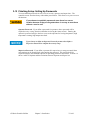
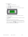
3-12! Finishing Setup: Setting Up Passwords ..................................................................... 37!
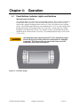
CHAPTER 4:! OPERATION ....................................................... 39!
4-1! Panel Buttons, Indicator Lights, and Switches ............................................................ 39!
Microprocessor Controller ................................................................................... 39!
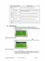
4-2! Initial Start-up .............................................................................................................. 40!
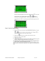
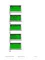
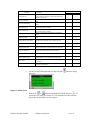
4-3! Status Screens ............................................................................................................ 42!

GP Series Portable Chillers vi
4-4
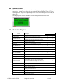
! Access Levels ............................................................................................................. 45!
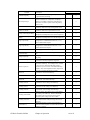
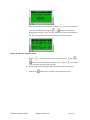
4-5! Controller Setpoints ..................................................................................................... 45!
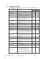
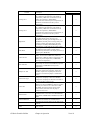
4-6! Configuration Settings ................................................................................................. 49!
4-7! Alarms ......................................................................................................................... 51!
4-8! Optional Communications ........................................................................................... 51!
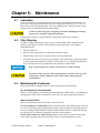
CHAPTER 5:! MAINTENANCE ................................................. 52!
5-1! Lubrication ................................................................................................................... 52!
5-2! Filter Cleaning ............................................................................................................. 52!
5-3! Maintaining the Condenser ......................................................................................... 52!
Air- and Remote Air-Cooled Chillers ................................................................... 52!
Water-Cooled Chillers ......................................................................................... 52!
5-4! Maintaining the Evaporator ......................................................................................... 53!
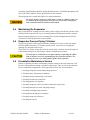
5-5! Evaporator Process Piping Y-Strainer ......................................................................... 53!
5-6! Preventative Maintenance Service .............................................................................. 53!
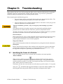
CHAPTER 6:! TROUBLESHOOTING ....................................... 54!
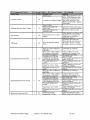
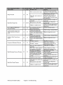
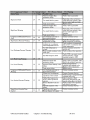
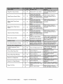
6-1! Identifying the Cause of a Problem ............................................................................. 54!
Non-Controller Related Issues ............................................................................ 60!
CHAPTER 7:! APPENDIX .......................................................... 62!
7-1! Technical Assistance ................................................................................................... 62!
Parts and Service Department ............................................................................ 62!
Sales and Contracting Department ..................................................................... 62!
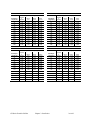
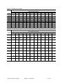
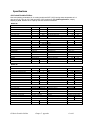
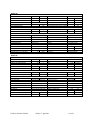
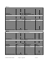
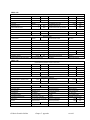
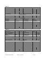
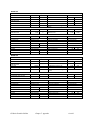
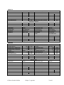
Specifications ........................................................................................................................ 63!
Air-Cooled Portable Chillers ................................................................................ 63!
Water-Cooled Portable Chillers ........................................................................... 68!
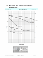
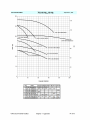
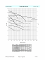
7-2! Pump Curves, Flow, and Pressure Considerations ..................................................... 73!
60 Hertz Pump Curves ........................................................................................ 73!
50 Hertz Pump Curves ........................................................................................ 75!
7-3! Remote Air-Cooled Chiller Configurations ................................................................... 78!
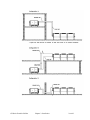
7-4! Typical Ductwork for Air-Cooled Chillers ..................................................................... 80!
7-5! Piping Diagrams .......................................................................................................... 82!

GP Series Portable Chillers Chapter 1: Safety 7 of 93
Chapter 1: Safety
1-1 How to Use This Manual
Use this manual as a guide and reference for installing, operating, and maintaining your
equipment. The purpose is to assist you in applying efficient, proven techniques that enhance
equipment productivity.
This manual covers only light corrective maintenance. No other maintenance should be
undertaken without first contacting a service engineer.
The Functional Description section outlines models covered, standard features, and optional
features. Additional sections within the manual provide instructions for installation, pre-
operational procedures, operation, preventive maintenance, and corrective maintenance.
The Installation chapter includes required data for receiving, unpacking, inspecting, and setup
of the equipment. We can also provide the assistance of a factory-trained technician to help
train your operator(s) for a nominal charge. This section includes instructions, checks, and
adjustments that should be followed before commencing with operation of the equipment.
These instructions are intended to supplement standard shop procedures performed at shift,
daily, and weekly intervals.
The Operation chapter includes a description of electrical and mechanical controls, in
addition to information for operating the equipment safely and efficiently.
The Maintenance chapter is intended to serve as a source of detailed assembly and
disassembly instructions for those areas of the equipment requiring service. Preventive
maintenance sections are included to ensure that your equipment provides excellent, long
service.
The Troubleshooting chapter serves as a guide for identification of most common problems.
Potential problems are listed, along with possible causes and related solutions.
The Appendix contains technical specifications, drawings, schematics, and parts lists. A
spare parts list with part numbers specific to your machine is provided with your shipping
paperwork package. Refer to this section for a listing of spare parts for purchase. Have your
serial number and model number ready when ordering.
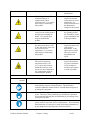
Safety Symbols Used in this Manual
The following safety alert symbols are used to alert you to potential personal injury hazards.
Obey all safety messages that follow these symbols to avoid possible injury or death.
DANGER indicates an imminently hazardous situation, which, if not avoided,
will result in death or serious injury.
WARNING indicates a potentially hazardous situation or practice which, if not
avoided, could result in death or serious injury.
CAUTION indicates a potentially hazardous situation or practice which, if not
avoided, may result in minor or moderate injury or in property damage.

GP Series Portable Chillers Chapter 1: Safety 8 of 93
Hazard Alert Symbol
Description/Explanation
Preventative
Maintenance
High Voltage Hazard. The
electrical enclosure is
supplied with 3-phase
electrical power. Use caution
when using or maintaining
this product.
Every six months
inspect all electrical
connections for secure
attachment. For
further information see
the Maintenance
Chapter in this manual
Cut/Crush Hazard. The air
cooled version of this product
has high speed rotating fan
blades. Use caution when
using or maintain this
product.
Every month inspect
the guarding around
the fan blade to ensure
proper installation and
working condition.
Hot Surface Hazard. When
the unit operates above 212F
(100C) the surface of the unit
may reach excessive
temperatures. Use caution
when using or maintaining
this product.
Every six months
inspect all surfaces for
signs of heat
degradation. If any
appear remove panel
and verify cause of
degradation and
repair.
Low Temperature Hazard.
This unit can operate at
temperatures below 32F
(0 C), and as such surfaces
within this unit may reach
excessively low temperatures.
Use caution when using or
maintaining this product.
Every six months
inspect all insulation
for proper installation.
If any insulation is
missing repair/replace
as soon as possible.
Mandatory
Symbol
Description/Explanation
Read Operators Manual. This equipment must be operated and
maintained by properly trained personnel. The information
contained within this manual must be read and understood prior to
operating this equipment.
Lock Out. This equipment is operated with 3-phase electrical
power. Therefore, when performing any maintenance operations
we recommend following the local standards for performing a lock-
out/tag-out procedure.
Wear Safety Gloves. This equipment operates above 212F (100C)
and its surfaces may reach excessive temperatures. We recommend
that technicians use safety gloves while performing maintenance to
protect hands from being exposed to these hot surfaces.

GP Series Portable Chillers Chapter 1: Safety 9 of 93
1-2 Warnings and Precautions
Our equipment is designed to provide safe and reliable operation when installed and operated
within design specifications, following national and local safety codes.
To avoid possible personal injury or equipment damage when installing, operating, or
maintaining this equipment, use good judgment and follow these safe practices:
! Follow all SAFETY CODES.
! Wear SAFETY GLASSES and WORK GLOVES.
! Disconnect and/or lock out power before servicing or maintaining the equipment.
! Use care when LOADING, UNLOADING, RIGGING, or MOVING this
equipment.
! Operate this equipment within design specifications.
! OPEN, TAG, and LOCK ALL DISCONNECTS before working on equipment.
You should remove the fuses and carry them with you.
! Make sure the equipment and components are properly GROUNDED before you
switch on power.
! When welding or brazing in or around this equipment, make sure
VENTILATION is ADEQUATE. PROTECT adjacent materials from flame or
sparks by shielding with sheet metal. An approved FIRE EXTINGUISHER
should be close at hand and ready for use if needed.
! Refrigeration systems can develop refrigerant pressures in excess of 500 psi
(3,447.5 kPa/ 34.47 bars). DO NOT CUT INTO THE REFRIGERATION
SYSTEM. This must be performed by a qualified service technician only.
! Do not restore power until you remove all tools, test equipment, etc., and the
equipment and related components are fully reassembled.
! Only PROPERLY TRAINED personnel familiar with the information in this
manual should work on this equipment.
We have long recognized the importance of safety and have designed and manufactured our
equipment with operator safety as a prime consideration. We expect you, as a user, to abide
by the foregoing recommendations in order to make operator safety a reality.
1-3 Responsibility
These machines are constructed for maximum operator safety when used under standard
operating conditions and when recommended instructions are followed in the maintenance
and operation of the machine.
All personnel engaged in the use of the machine should become familiar with its operation as
described in this manual.
Proper operation of the machine promotes safety for the operator and all workers in its
vicinity.
Each individual must take responsibility for observing the prescribed safety rules as outlined.
All warning and danger signs must be observed and obeyed. All actual or potential danger
areas must be reported to your immediate supervisor.

GP Series Portable Chillers Chapter 2: Functional Description 10 of 93
Chapter 2: Functional Description
2-1 Models Covered in This Manual
This manual provides operation, installation, and maintenance instructions for air-, water-and
remote air-cooled portable chillers. Model numbers are listed on the serial tag. Make sure you
know the model and serial number of your equipment before contacting the manufacturer for
parts or service.
Our portable chiller models are designated by approximate output in kW of cooling (20, 30,
40, 50, through 210) and the cooling method used: -A for air-cooled, -W for water-cooled,
and –R for remote-air cooled.
2-2 General Description
Our portable chillers are reliable, accurate, and easy to use process cooling units. They are
available in air-, water-, and remote air-cooled designs in a range of sizes from 20 kW
through 210 kW (5 through 60 tons of refrigeration). All are self-contained, fully portable and
shipped ready to use. (Remote air-cooled chillers require field installation by qualified
technicians.) In the standard configuration the chiller basically consists of a pump, tank,
compressor, condenser, evaporator, and a control platform. All of these components, plus the
other integral components to maintain the leaving fluid temperature, are described throughout
this Chapter as well as Chapters 3 and 4.
Standard range of operation is 20ºF to 80ºF (-7ºC to 27ºC) for applications using a
water/glycol mix and 45ºF to 80ºF (7º to 27ºC) for water only applications.
Typical Applications
This series of portable chillers can be used in any application that needs a constant source of
cool process water. Typical applications include, but are not limited to, the following:
• Injection molding
• Blow molding
• Extrusion
• Thermoforming
• Machine tool
• Metal plating
• Thermal spray
• After-coolers (air compressors, dryers, etc.)
• Laser
• Printing (offset, gravure, digita)
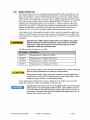
System Limitations
These packaged chillers should be chosen using the following criteria:
Process heat load – Choose the size of the chiller so that rated capacity is no greater than
10% more than the process heat load.


GP Series Portable Chillers Chapter 2: Functional Description 12 of 93
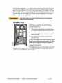
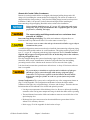
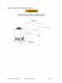
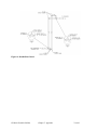
Refrigeration Circuit
Air-, water-, and remote air-cooled refrigerant condensing differ only in the way the
compressed gas is condensed to a liquid. Shown below is a water-cooled version.
The refrigerant is compressed in the compressor and
flows through the discharge line as a gas to the
condenser.
There it gives up its heat as it condenses to a liquid
in the condenser.
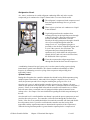
Liquid refrigerant from the condenser heat
exchanger flowing in the liquid line passes through
a shut-off valve into a filter/dryer that removes
moisture and other contaminants. After the
filter/dryer the refrigerant passes through a solenoid
valve to prevent liquid migration when the
compressor is off. A refrigerant sight glass is
provided to view the flow of liquid refrigerant, and
to view if the system is free of moisture. The
refrigerant then passes through the thermal
expansion valve, which allows the refrigerant to
expand (boil off) and cool (remove the heat from)
the fluid inside of the evaporator.
From the evaporator the refrigerant gas flows
through the suction line back into the compressor.
A modulating electronic hot gas bypass valve is used to control cooling capacity during
intermittent or partial load conditions. This feature contributes substantially to chiller
longevity by eliminating excessive cycling of the compressor and providing close
temperature control.
System Control
Putting this all together, the controller maintains the desired leaving fluid temperature using
multiple inputs to determine if, when and for how long the compressor(s) are on, and if,
when, the percent open and for how long the modeling hot gas bypass valve is on.
Once the unit’s power is enabled and the controller is turned on (see Chapter 4 for more
details on the operation of the controller) it verifies there is sufficient fluid level in the tank (if
present). If there is not enough fluid in the tank the controller will warn the user, or fill the
tank with water from a connected source if equipped with the optional automatic water
makeup valve. See Chapter 3 for more information regarding the initial setup and startup of
the unit.
Once the tank level is satisfied and the start button is pressed, the process pump turns on and
provides flow to the process. The controller verifies the flow through the electronic flow
switch. If the flow is not established within 10 seconds the controller will alarm and disable
the refrigeration circuit. Upon flow verification the controller uses the leaving fluid
temperature and the setpoint temperature to determine the operation of the compressor(s).
When the leaving fluid temperature is greater than the setpoint plus the “compressor on

GP Series Portable Chillers Chapter 2: Functional Description 13 of 93
differential” value the controller will enable the compressor; if equipped with two
compressors the controller will enable the one with the least amount of hours. The second
compressor will be enabled if the leaving fluid temperature remains above the setpoint plus
the “compressor on differential” value for more than 60 seconds.
The hot gas valve is designed to trim the load of one compressor and will modulate in order
to meet the desired leaving fluid setpoint via a PID algorithm. After the compressor starts,
the hot gas valve is allowed to modulate. The compressor will shut off if the leaving fluid
temperature drops below the “compressor off differential” and the hot gas valve is at 100%
for the “compressor off delay” time. The hot gas will reset to 0% when the compressor is off.
There is a “compressor anticyle” timer that will delay the time between compressor starts to
prevent short cycling of the compressor. This is a start to start timer set at 5 minutes. For
example, if the compressor has been running for 5 minutes and shuts off, then the compressor
can start immediately if the demand is there. If it has only been running for 2 minutes, then it
would not be able to start again for 3 minutes.
For a unit with two compressors, the second compressor or lag compressor starts when the
lead compressor is on, the hot gas is at 0%, and the leaving fluid temperature is above the
setpoint plus the “compressor on differential”. There is also an adjustable “lag compressor on
delay” timer. Before starting either compressor, the compressor with the least amount of
runtime hours is considered the lead compressor and the first to start. When both
compressors are running, the compressor with the most hours is considered the lead
compressor and is the first to stop. The lead compressor will shut off if the leaving fluid
temperature drops below the “compressor off differential” and the hot gas valve is at 100%
for the “lead compressor off delay” time. The compressor anti-cycle timers are active with
the two compressor units.
There will be two PID controls running simultaneously for determining the position of the hot
gas valve. One PID output will be based on leaving fluid temperature and the other based on
a minimum saturated suction temperature for freeze protection. The hot gas valve position
will be determined by which output is greater. If it is controlling to the saturated suction
temperature to prevent freezing, a warning will display on the screen that the hot gas is in this
mode. Once the control goes back to setpoint control, the warning will disappear. The
saturated suction temperature is calculated from the suction pressure and the type of
refrigerant.
The discharge pressure is controlled using an analog output signal to drive a fan for air-
cooled units or a water regulating valve for water-cooled units. The output signal is
determined from a PID algorithm using a discharge pressure transducer as the process
variable. The VFD or water regulating valve is controlled from the analog output to an
adjustable discharge pressure setpoint. The analog output starts at the initial “discharge
pressure start” % for a given time delay (discharge pressure hold). After the time delay, it
will control to the discharge pressure setpoint via the PID control. There is also a setting to
control the discharge pressure to the most efficient value.
2-3 Standard Features
Mechanical Features
Compressor – Hermetic scroll compressors.
Evaporator – Stainless steel copper brazed plate evaporators.

GP Series Portable Chillers Chapter 2: Functional Description 14 of 93
Air-Cooled Condenser – Aluminum fin/ tube with washable filters, packaged units only.
Variable speed fan control standard for all remote air cooled condensers and GPAC70
through 210. Optional on GPAC20 through 50.
Water-Cooled Condenser – Tube-in-tube condensers (GPWC20 – GPWC50), Shell-and-
tube condensers (GPWC70 – GPWC210). All come with electronic cooling water regulating
valves.
Remote Air-Cooled Condenser– Aluminum fin/tube with low ambient control down to
–20ºF (-29ºC) via variable-speed fan(s).
Reservoir – GP20 and GP30 models use a 20 gallon (75 liter) polyethylene tank, GP40 and
GP50 models use a 40 gallon (150 liter) polyethylene tank, GP70 thru GP105 models use a
70 gallon (265 liter) polyethylene tank, GP140 thru GP210 models use a 140 gallon (530
liter) polyethylene tank. 304SS is available as an option for all sizes.
Piping – Non-ferrous chilled water piping
Pump – ODP motors (TEFC Optional)—horizontally mounted stamped stainless steel
construction.
Other Mechanical Features
• Low process water thermal flow switch
• NEMA-rated fan motor(s) on air-cooled models
• Galvanized structural steel frame, polyester powder coat painted cabinetry
• Internal process water bypass valve for system protection only
• Fully insulated refrigeration and process water piping
• 20 mesh Y strainer on process water piping into the evaporator
• Tank level indication via operator interface
• Pump pressure indication via operator interface
Electrical Features
• Fully accessible NEMA 4/12-style electrical control enclosure
• Single-point power and ground connection
• Non-fused disconnect switch, lockable
• Branch circuit protection
• 208-230/3/60, 460/3/60, 575/3/60 volt; 400/3/50 volt
Refrigeration Features
• HFC-410a refrigerant
• Electronic modulating hot gas bypass capacity control
• High refrigerant pressure cutout switch (manual reset)
• Suction and discharge pressure transducers.
• High refrigerant pressure spring actuated relief valve

GP Series Portable Chillers Chapter 2: Functional Description 15 of 93
• Multiple refrigeration access ports
• Liquid line shut-off ball valves
• Filter-dryer
• Sight glass
• Externally equalized thermal expansion valve
• Liquid line solenoid
• Compressor crankcase heater
Controller Features
• Off-the-shelf microprocessor-based PID controller with To Process, From Process and
Set Point readout
• Time delay for proof of water flow/pressure (models w/pump only)
• Low refrigerant pressure time delay for low ambient start-up on remote air-cooled and
air-cooled chillers with the variable-speed fan option.
• 8 line x 22 character display with status, alarm, and service screens
• Display has magnetic back and can be mounted anywhere.
Other Features
• One year labor warranty and one year compressor warranty
• Two year parts warranty
• Three year limited controller warranty
2-4 Safety Devices and Interlocks
Protect the system from freezing with inhibited industrial grade glycol 20ºF
below the leaving water temperature set point. Condensation may form inside
the pump tank and dilute the mixture, therefore the freezing point should be
verified periodically. See Figure 6 on page 18 for the correct mixture.
Crankcase Heater
All of the chillers are equipped with a compressor crankcase heater. It is wired through the
control transformer that operates continuously whenever power is applied to the chiller, and
the compressors are off.
Energize the crankcase heater for at least 24 hours before initial startup to
drive dissolved refrigerant from the compressor oil. Failure to do so will
damage the compressor. If unit is mounted outdoors, power to the unit (and
the main power switch) must remain on 24 hours per day, 7 days per week to
prevent liquid migration to the compressor.


GP Series Portable Chillers Chapter 2: Functional Description 17 of 93
Flow Switch
The thermal dispersion flow switch cutout device, mounted in the process piping, shuts down
the chiller if it senses that the water/glycol flow rate through the evaporator has dropped
below an acceptable level. The flow switch opens the control circuit and shuts down the
pump and the chiller.
Remote Start/Stop Interlock
An additional contact is provided to allow the remote starting or stopping of the chiller. To
use this feature install a switch or dry contact interlock connected in series between terminals
4 and 23. Refer to the electrical schematic supplied in the control enclosure. Once the wiring
is complete the controller will need to be reconfigured in the supervisor settings.
2-5 Optional Features
Options marked with “*” indicate options that can be factory installed or retrofitted in the
field.
Automatic Water Make-Up*. Not available on chillers less reservoir tank. This option
includes an electric water solenoid valve, and the necessary internal piping to connect the
chiller to a make-up water source. The controller uses the standard tank level pressure
transducer to determine when to fill the tank. See Appendix for typical piping diagrams.
Customer piping must provide backflow protection and venting of tank to
atmosphere to prevent over-pressurization of the reservoir tank (not needed for
open tank). See Section 7-7 for flow schematics.
Process Water Side-stream Filter*. Not available on chillers less pump and reservoir tank.
This option includes a 50 micron filter, flow indicator, ball valve for throttling water flow,
and the necessary piping to provide constant filtering of the process water at about one gallon
per minute (1 gpm/3.8lpm).
General Fault Indicator Audible/Visual Alarm*. This option includes a 100 dB audible
alarm horn/ visual alarm strobe and silence button with provisions for customer wiring
indication interlock. The alarm signals anytime that a fault is recognized during the operation
of the chiller.
Communications Options*. This option provides the capability for the unit’s controller to
communicate with an external device using a variety of serial communication protocols.
Currently the unit can communicate over RS-485 Modbus RTU, BACNet, LONWorks,
Ethernet Modbus.
High Pressure Fans. Provides either 0.3” WC (75 Pa) or 1.0”WC (250 Pa) of external static
pressure on fan discharge. High-pressure fans are necessary and must be included in chiller
installations where exiting air exhausts through ductwork.
The 0.3” WC (75 Pa) static fan can be retrofitted without sheet metal modification, but will
require changing out fan housing, fan blades, fan motors and electrical components.
Variable Speed Fan – GPAC20-50. Reduces the speed of the fan based on refrigerant
pressure and system load, allowing the chiller to operate in ambient temperatures below 75ºF
(24ºC). This option will also reduce fan noise in lower ambient temperatures and low loads.


GP Series Portable Chillers Chapter 3: Installation 20 of 93
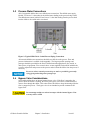
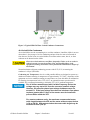
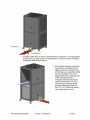
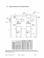
3-3 Process Water Connections
All of our portable chillers have two chilled water connections. The chilled water supply,
labeled “To Process” is the outlet for the chilled water leading to the process being cooled.
The chilled water return, labeled “From Process” is the inlet leading from the process back
into the chiller to be cooled and re-circulated.
Figure 2: Typical GP20-50 Air Cooled Process Piping Connections
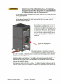
All external chilled water connections should be run full size to the process. Flow and
pressure information is available in the Appendix. The largest possible openings and
passages should be provided for the flow of chilled water through platens, dies, molds, or
other pieces of equipment. Flow control valves are not supplied, but should be added to the
system to adjust flow and pressure to the process and to isolate the chiller from the process if
necessary.
Be sure to reduce external pressure drop as much as possible by generously
sizing piping and tooling water passageways.
3-4 Bypass Valve Considerations
Our portable chillers have an internal manual bypass valve. If the flow is stopped to the
process while the chiller is running, the factory-set bypass valve allows a small amount of
water to flow through the chiller. This action allows the chiller to keep functioning while the
flow is stopped to process. The bypass valve is not intended to provide continuous full
bypass flow.
Do not attempt to adjust or otherwise tamper with the internal bypass. Your
warranty will be voided.
!
Page is loading ...
Page is loading ...
Page is loading ...
Page is loading ...
Page is loading ...
Page is loading ...
Page is loading ...
Page is loading ...
Page is loading ...
Page is loading ...
Page is loading ...
Page is loading ...
Page is loading ...
Page is loading ...
Page is loading ...
Page is loading ...
Page is loading ...
Page is loading ...
Page is loading ...
Page is loading ...
Page is loading ...
Page is loading ...
Page is loading ...
Page is loading ...
Page is loading ...
Page is loading ...
Page is loading ...
Page is loading ...
Page is loading ...
Page is loading ...
Page is loading ...
Page is loading ...
Page is loading ...
Page is loading ...
Page is loading ...
Page is loading ...
Page is loading ...
Page is loading ...
Page is loading ...
Page is loading ...
Page is loading ...
Page is loading ...
Page is loading ...
Page is loading ...
Page is loading ...
Page is loading ...
Page is loading ...
Page is loading ...
Page is loading ...
Page is loading ...
Page is loading ...
Page is loading ...
Page is loading ...
Page is loading ...
Page is loading ...
Page is loading ...
Page is loading ...
Page is loading ...
Page is loading ...
Page is loading ...
Page is loading ...
Page is loading ...
Page is loading ...
Page is loading ...
Page is loading ...
Page is loading ...
Page is loading ...
Page is loading ...
Page is loading ...
Page is loading ...
Page is loading ...
Page is loading ...
Page is loading ...
-
 1
1
-
 2
2
-
 3
3
-
 4
4
-
 5
5
-
 6
6
-
 7
7
-
 8
8
-
 9
9
-
 10
10
-
 11
11
-
 12
12
-
 13
13
-
 14
14
-
 15
15
-
 16
16
-
 17
17
-
 18
18
-
 19
19
-
 20
20
-
 21
21
-
 22
22
-
 23
23
-
 24
24
-
 25
25
-
 26
26
-
 27
27
-
 28
28
-
 29
29
-
 30
30
-
 31
31
-
 32
32
-
 33
33
-
 34
34
-
 35
35
-
 36
36
-
 37
37
-
 38
38
-
 39
39
-
 40
40
-
 41
41
-
 42
42
-
 43
43
-
 44
44
-
 45
45
-
 46
46
-
 47
47
-
 48
48
-
 49
49
-
 50
50
-
 51
51
-
 52
52
-
 53
53
-
 54
54
-
 55
55
-
 56
56
-
 57
57
-
 58
58
-
 59
59
-
 60
60
-
 61
61
-
 62
62
-
 63
63
-
 64
64
-
 65
65
-
 66
66
-
 67
67
-
 68
68
-
 69
69
-
 70
70
-
 71
71
-
 72
72
-
 73
73
-
 74
74
-
 75
75
-
 76
76
-
 77
77
-
 78
78
-
 79
79
-
 80
80
-
 81
81
-
 82
82
-
 83
83
-
 84
84
-
 85
85
-
 86
86
-
 87
87
-
 88
88
-
 89
89
-
 90
90
-
 91
91
-
 92
92
-
 93
93


Sterling GP Series Operation and Installation Manual
- Type
- Operation and Installation Manual
Ask a question and I''ll find the answer in the document
Finding information in a document is now easier with AI
Related papers
-
Sterling 882.93092.01 User manual
-
-
-
-
-
-
-
-
-
Other documents
-
HP A0554832 User manual
-
Sterling Power Products 30F User manual
-
 SterlingTEK A0551797 User manual
-
Trane Stealth Helical Rotary Model RTAE Installation and Maintenance Manual
-
-
-
Conair VL Series User manual
-
-
Trane CVHG Installation, Operation and Maintenance Manual
-
