Page is loading ...

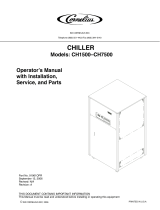
2–40 hp Portable Chillers
Part Number: A0554831
Bulletin Number: SC2-610C.10
Effective: 4/3/2008
Write Down Your Serial Numbers Here For Future Reference:
_________________________ _________________________
_________________________ _________________________
_________________________ _________________________
We are committed to a continuing program of product improvement.
Specifications, appearance, and dimensions described in this manual are subject to change without notice.
DCN No. ____________
© Copyright 2008
All rights reserved.

2-40 HP Portable Chillers ii
Shipping Information
Unpacking and Inspection
You should inspect your equipment for possible shipping damage. Thoroughly check the
equipment for any damage that might have occurred in transit, such as broken or loose wiring
and components, loose hardware and mounting screws, etc.
In the Event of Shipping Damage
According to the contract terms and conditions of the Carrier, the responsibility of the
Shipper ends at the time and place of shipment.
Notify the transportation company’s local agent if you discover damage
Hold the damaged goods and packing material for the examining agent’s inspection. Do not
return any goods before the transportation company’s inspection and authorization.
File a claim with the transportation company. Substantiate the claim by referring to the
agent’s report. A certified copy of our invoice is available upon request. The original Bill of
Lading is attached to our original invoice. If the shipment was prepaid, write us for a
receipted transportation bill.
Advise customer service regarding your wish for assistance and to obtain an RMA (return
material authorization) number.
If the Shipment is Not Complete
Check the packing list as back-ordered items are noted on the packing list. In addition to the
equipment itself, you should have:
Bill of lading
Packing list
Operating and Installation packet
Electrical schematic and panel layout drawings
Component instruction manuals (if applicable)
Re-inspect the container and packing material to see if you missed any smaller items during
unpacking.
If the Shipment is Not Correct
If the shipment is not what you ordered, contact the parts and service department
immediately at [262] 641-8610. Have the order number and item number available. Hold the
items until you receive shipping instructions.
Returns
Do not return any damaged or incorrect items until you receive shipping instructions from the
shipping department.

2-40 HP Portable Chillers iii
Table of Contents
CHAPTER 1: SAFETY .................................................................6
1-1 How to Use This Manual.............................................................................................6
Safety Symbols Used in this Manual.....................................................................6
1-2 Warnings and Precautions..........................................................................................7
1-3 Responsibility..............................................................................................................7
CHAPTER 2: FUNCTIONAL DESCRIPTION...............................8
2-1 Models Covered in This Manual..................................................................................8
2-2 General Description.....................................................................................................9
Chilled Water Circuit..............................................................................................9
Refrigeration Circuit...............................................................................................9
2-3 Standard Features.....................................................................................................10
Mechanical Features...........................................................................................10
Electrical Features...............................................................................................11
Refrigeration Features.........................................................................................11
Controller Features..............................................................................................11
Other Features ....................................................................................................11
2-4 Safety Devices and Interlocks...................................................................................12
High/Low Thermostat Control..............................................................................12
Crankcase Heater ...............................................................................................12
High Pressure Cutout..........................................................................................12
Low Pressure Cutout...........................................................................................13
Oil Pressure Safety Switch……………………………………………………………13
Fan Cycling Switch..............................................................................................13
Pressure Switch ..................................................................................................13
Flow Switch .........................................................................................................13
Remote Start/Stop Interlock ................................................................................13
2-5 Optional Features......................................................................................................14
CHAPTER 3: INSTALLATION ...................................................17
3-1 Uncrating...................................................................................................................17
3-2 Electrical Connections...............................................................................................17
3-3 Process Water Connections......................................................................................18
3-4 Bypass Valve Considerations....................................................................................18
3-5 Galvanic Corrosion Considerations...........................................................................18
3-6 Water Treatment Considerations ..............................................................................18
3-7 Condenser Considerations........................................................................................19
Water-Cooled Chiller Condensers.......................................................................19
Air-Cooled Chiller Condensers............................................................................19
Remote Air-Cooled Chiller Condensers ..............................................................20
3-8 Checking Motor Direction..........................................................................................24
Three-Phase Compressors .................................................................................24
Water Pumps.......................................................................................................24
Condenser Fan....................................................................................................24
3-9 Water Reservoir ........................................................................................................25
3-10 Automatic Water Make-Up Option.............................................................................27

2-40 HP Portable Chillers iv
3-11 Initial Start-Up............................................................................................................28
CHAPTER 4: OPERATION ........................................................29
4-1 Panel Buttons, Indicator Lights, and Switches..........................................................29
Microprocessor Controllers..................................................................................29
Graphic Panel......................................................................................................32
4-2 Start-up......................................................................................................................35
4-3 Setting the Process Water Temperatures.................................................................35
4-4 Auto-Tuning...............................................................................................................35
4-5 Optional Communications.........................................................................................35
4-6 Programming the Electronic High/Low Thermostat...................................................36
CHAPTER 5: MAINTENANCE...................................................38
5-1 Lubrication.................................................................................................................38
5-2 Filter Cleaning...........................................................................................................38
5-3 Maintaining the Condenser .......................................................................................39
Air- and Remote Air-Cooled Chillers ...................................................................39
Water-Cooled Chillers .........................................................................................39
5-4 Maintaining the Evaporator .......................................................................................39
5-5 Evaporator Process Piping Y-Strainer.......................................................................39
5-6 Preventative Maintenance Service............................................................................40
CHAPTER 6: TROUBLESHOOTING.........................................41
CHAPTER 7: APPENDIX ...........................................................43
7-1 Returned Material Policy...........................................................................................43
7-2 Technical Assistance.................................................................................................44
Parts Department ................................................................................................44
Service Department.............................................................................................44
Sales Department................................................................................................44
Contract Department...........................................................................................44
7-3 Drawings and Specifications.....................................................................................45
2 hp and 3 1/2 hp Air-Cooled Portable Chillers...................................................45
5 hp and 7.5 hp Air-Cooled Portable Chillers......................................................46
10 hp and 15 hp Air-Cooled Portable Chillers.....................................................47
20 hp, 25 hp, and 30 hp Air-Cooled Portable Chillers.........................................48
2 hp and 3.5 hp Water-Cooled Portable Chillers.................................................49
5 hp and 7.5 hp Water-Cooled Portable Chillers.................................................50
10 hp and 15 hp Water-Cooled Portable Chillers................................................51
20 hp, 25 hp, and 30 hp Water-Cooled Portable Chillers....................................52
35 hp and 40 hp Water-Cooled Portable Chillers................................................53
5 hp and 7.5 hp Remote Air-Cooled Portable Chillers.........................................54
10 hp and 15 hp Remote Air-Cooled Portable Chillers........................................55
20 hp through 40 hp Remote Air-Cooled Portable Chillers .................................56
Remote Condenser Assembly Models................................................................57
7-4 Pump Curves, Flow, and Pressure Considerations...................................................58
60 Hertz Pump Curves........................................................................................59
50 Hertz Pump Curves........................................................................................60
Water Pressure Drop Tables...............................................................................61

2-40 HP Portable Chillers v
Flow and Pressure Considerations......................................................................61
Recirculation Pump Specifications......................................................................61
7-5 Remote Air-Cooled Chiller Configurations ................................................................62
7-6 Typical Ductwork for Air-Cooled Chillers...................................................................63
7-7 Piping Diagrams........................................................................................................64
Central and Gravity Return Piping with Standpipe Diagram................................64
Typical Piping Schematic, 2 and 3 1/2 hp Models...............................................65
Typical Piping Schematic, 5 hp through 40 hp, One-Pump Models....................66
Typical Piping Schematic, 5 hp through 40 hp, Two-Pump Models....................67
Typical Piping Schematic, 5 hp through 40 hp, No-Pump Models ......................68
Typical Piping Schematic, 5 hp through 40 hp, One-Pump Models....................69
7-8 Electrical Schematics................................................................................................70

2-40 HP Portable Chillers Chapter 1: Safety 6 of 70
Chapter 1: Safety
1-1 How to Use This Manual
Use this manual as a guide and reference for installing, operating, and maintaining your
equipment. The purpose is to assist you in applying efficient, proven techniques that enhance
equipment productivity.
This manual covers only light corrective maintenance. No other maintenance should be
undertaken without first contacting a service engineer.
The Functional Description section outlines models covered, standard features, and optional
features. Additional sections within the manual provide instructions for installation, pre-
operational procedures, operation, preventive maintenance, and corrective maintenance.
The Installation chapter includes required data for receiving, unpacking, inspecting, and setup
of the equipment. We can also provide the assistance of a factory-trained technician to help
train your operator(s) for a nominal charge. This section includes instructions, checks, and
adjustments that should be followed before commencing with operation of the equipment.
These instructions are intended to supplement standard shop procedures performed at shift,
daily, and weekly intervals.
The Operation chapter includes a description of electrical and mechanical controls, in
addition to information for operating the equipment safely and efficiently.
The Maintenance chapter is intended to serve as a source of detailed assembly and
disassembly instructions for those areas of the equipment requiring service. Preventive
maintenance sections are included to ensure that your equipment provides excellent, long
service.
The Troubleshooting chapter serves as a guide for identification of most common problems.
Potential problems are listed, along with possible causes and related solutions.
The Appendix contains technical specifications, drawings, schematics, and parts lists. A
spare parts list with part numbers specific to your machine is provided with your shipping
paperwork package. Refer to this section for a listing of spare parts for purchase. Have your
serial number and model number ready when ordering.
Safety Symbols Used in this Manual
The following safety alert symbols are used to alert you to potential personal injury hazards.
Obey all safety messages that follow these symbols to avoid possible injury or death.
DANGER indicates an imminently hazardous situation which, if not avoided, will result in
death or serious injury.
WARNING indicates a potentially hazardous situation or practice which, if not avoided,
could result in death or serious injury.
CAUTION indicates a potentially hazardous situation or practice which, if not avoided,
may result in minor or moderate injury or in property damage.

2-40 HP Portable Chillers Chapter 1: Safety 7 of 70
1-2 Warnings and Precautions
Our equipment is designed to provide safe and reliable operation when installed and operated
within design specifications, following national and local safety codes.
To avoid possible personal injury or equipment damage when installing, operating, or
maintaining this equipment, use good judgment and follow these safe practices:
9 Follow all SAFETY CODES.
9 Wear SAFETY GLASSES and WORK GLOVES.
9 Disconnect and/or lock out power before servicing or maintaining the equipment.
9 Use care when LOADING, UNLOADING, RIGGING, or MOVING this
equipment.
9 Operate this equipment within design specifications.
9 OPEN, TAG, and LOCK ALL DISCONNECTS before working on equipment.
You should remove the fuses and carry them with you.
9 Make sure the equipment and components are properly GROUNDED before you
switch on power.
9 When welding or brazing in or around this equipment, make sure
VENTILATION is ADEQUATE. PROTECT adjacent materials from flame or
sparks by shielding with sheet metal. An approved FIRE EXTINGUISHER
should be close at hand and ready for use if needed.
9 Refrigeration systems can develop refrigerant pressures in excess of 500 psi
(3,447.5 kPa/ 34.47 bars). DO NOT CUT INTO THE REFRIGERATION
SYSTEM. This must be performed by a qualified service technician only.
9 Do not restore power until you remove all tools, test equipment, etc., and the
equipment and related components are fully reassembled.
9 Only PROPERLY TRAINED personnel familiar with the information in this
manual should work on this equipment.
We have long recognized the importance of safety and have designed and manufactured our
equipment with operator safety as a prime consideration. We expect you, as a user, to abide
by the foregoing recommendations in order to make operator safety a reality.
1-3 Responsibility
These machines are constructed for maximum operator safety when used under standard
operating conditions and when recommended instructions are followed in the maintenance
and operation of the machine.
All personnel engaged in the use of the machine should become familiar with its operation as
described in this manual.
Proper operation of the machine promotes safety for the operator and all workers in its
vicinity.
Each individual must take responsibility for observing the prescribed safety rules as outlined.
All warning and danger signs must be observed and obeyed. All actual or potential danger
areas must be reported to your immediate supervisor.

2-40 HP Portable Chillers Chapter 2: Functional Description 8 of 70
Chapter 2: Functional Description
2-1 Models Covered in This Manual
This manual provides operation, installation, and maintenance instructions for air- and water-
cooled portable chillers. Model numbers are listed on the serial tag. Make sure you know the
model and serial number of your equipment before contacting the manufacturer for parts or
service.
Our portable chiller models are designated by approximate compressor horsepower (2, 3 1/2,
5, 7 1/2, 10, etc) and the cooling method used: -A for air-cooled, -W for water-cooled, and –R
for remote-air cooled.

2-40 HP Portable Chillers Chapter 2: Functional Description 9 of 70
2-2 General Description
Our portable chillers are reliable, accurate, and easy to use process cooling units. They are
available in air-, water-, and remote air-cooled designs in a range of sizes from 2 to 40 tons.
All are self-contained, fully portable and shipped ready to use. (Remote air-cooled chillers
require field installation by qualified technicians.)
Standard range of operation is 30ºF to 65ºF (-1ºC to 18ºC) for applications using a
water/glycol mix and 45ºF to 65ºF (7º to 18ºC) for water only applications.
A factory installed crankcase pressure regulating valve option is available for processes
requiring a leaving water temperature of up to 75ºF (24ºC).
Chilled Water Circuit
Cooling water “To Process” and “From Process” connections are made at the gate valves
provided outside the unit. Warm coolant (water and glycol mixture) returns from the process
and goes into the reservoir tank. The coolant is then pumped through the evaporator where it
is cooled. The coolant flows to the process and returns to repeat the cycle.
A pressure actuated process water bypass valve located between the supply line and reservoir
tank (single pump models only) allows minimal flow through the unit during the intermittent
fluctuating flow conditions. It is not intended to provide continuous full bypass flow.
This minimal flow allows the temperature sensor to signal the controller to shut down the
compressor because of the drop in process water temperature. Typically the flow switch shuts
down the chiller in this low flow condition.
The 2 hp and 3 1/2 hp models have a 1/4” poly-tubing constant bypass to provide additional
process water bypass to prevent system freeze-up.
Refrigeration Circuit
Air-, water-, and remote air-cooled refrigerant condensing differs only in the way the
compressed gas is condensed to a liquid.
Liquid refrigerant from the condenser heat exchanger flowing in the liquid line passes
through a shut-off valve (5 hp to 40 hp chillers only) into a filter/dryer that removes moisture
and other contaminants. A refrigerant sight glass is provided. The refrigerant then passes
through the thermal expansion valve, which allows the refrigerant to expand (boil off) and
cool the fluid inside of the evaporator. The refrigerant gas flows through the suction linen
back into the compressor.
The refrigerant is compressed in the compressor and flows through the discharge line as a gas
to the condenser. There it gives up its heat as it condenses to a liquid in the condenser.
A hot gas bypass valve is used to control cooling capacity during intermittent or partial load
conditions. This feature contributes substantially to chiller longevity by eliminating excessive
cycling of the compressor and providing close temperature control.

2-40 HP Portable Chillers Chapter 2: Functional Description 10 of 70
2-3 Standard Features
Mechanical Features
Compressor. Hermetic scroll compressors are used on 2 hp through 30 hp (1.49 through
23.37 kW) models. Semi-hermetic discus compressors are used on the 35 hp and 40 hp (26.20
and 29.83 kW) models.
Evaporator. Stainless steel copper brazed plate evaporators are used on 2 hp through 30 hp
models. Shell and tube evaporators are used on the 35 hp and 40 hp models.
Air-Cooled Condenser. Aluminum fin/copper tube with washable filters, package unit only.
Water-Cooled Condenser. 2 hp to 7.5 hp models use tube-in-tube condensers. 10 hp to 40
hp use cleanable shell and tube condensers. All come with cooling water regulating valves
for cooling tower water or city water.
Remote Air-Cooled Condenser. 5 hp to 40 hp only. Aluminum fin/copper tube with low
ambient control down to –20ºF (-29ºC) via pressure-actuated fan staging and a variable-speed
primary fan.
Reservoir. 2 hp and 3 1/2 hp models use a 6 gallon polyethylene tank. 5 hp and 7.5 hp
models use a 20 gallon polyethylene tank. 10 hp and 15 hp models use a 40 gallon
polyethylene tank. 20 hp to 30 hp models use an 80 gallon polyethylene tank, and 40 hp
models use a 65 gallon stainless steel tank.
Piping. Non-ferrous piping for 2 hp through 30 hp models. 40 hp models have non-ferrous
piping.
Pump. ODP motors—horizontally mounted stamped stainless steel or cast bronze
construction.
Other Mechanical Features
• External fill/drain sight glass
• Low process water pressure switch on 2 hp and 3 1/2 hp models
• Low process water flow switch on 5 hp to 40 hp models
• Galvanized steel mounting rails for remote air-cooled models
• NEMA-rated fan motor(s) on air-cooled models
• Galvanized structural steel frame, painted cabinetry, with 2 1/2” swivel casters on 2 hp
and 3 1/2 hp models. 4” swivel casters on 5 hp to 15 hp models, and 5” swivel casters
with brake on 20 hp to 40 hp models.
• Valved process water connections
• Pressure-actuated process water bypass valve for system protection only; on single
pump models only
• To process 2 1/2” dual scale liquid-filled water pressure gauge
• Fully insulated refrigeration and process water piping
• Isolated fan section on air-cooled models, allowing chiller to run during maintenance
• 20 mesh Y strainer on process water piping into the evaporator

2-40 HP Portable Chillers Chapter 2: Functional Description 11 of 70
Electrical Features
• Fully accessible NEMA 12-style electrical control enclosure
• Single-point power and ground connection
• Non-fused disconnect switch, lockable
• Branch circuit fusing
• 208-230/3/60 and 460/3/60 volt (consult factory for other voltages)
• 208-230/1/60 volt on 2 and 3 1/2 hp models
Refrigeration Features
• R-22 refrigerant
• Hot gas bypass capacity control
• High discharge temperature cutout on 2 hp to 10 hp models
• High and low refrigerant pressure cutout switches
• Fan cycling switch (5 hp to 30 hp air-cooled models only)
• High pressure spring actuated relief valve
• Multiple refrigeration access ports
• Hot gas bypass and liquid line shut-off ball valves on 5 hp to 40 hp models
• Filter-dryer
• Sight glass
• Balanced port thermal expansion valve
Controller Features
• Off-the-shelf microprocessor-based PID auto-tuning controller with To Process and
Set Point LED readout
• Microprocessor temperature switch with LCD display for process water freeze
protection compressor cutout, and high process water temperature pump cutout
• Electronic time delay for proof of water flow/pressure (models w/pump only)
• Off-delay water flow timer to prevent short cycling (models w/pump only)
• Low refrigerant pressure switch, override timer for low ambient start-up on remote air-
cooled and air-cooled chillers with the variable-speed fan option.
• Graphic control panel with indicating and warning status lights
Other Features
• One year labor warranty and one year compressor warranty
• Two year parts warranty
• Three year limited controller warranty

2-40 HP Portable Chillers Chapter 2: Functional Description 12 of 70
2-4 Safety Devices and Interlocks
High/Low Thermostat Control
The high/low thermostat is a cutout device that protects the chiller system in two ways. Stage
one of the thermostat shuts down the compressor if the chilled process water/glycol
temperature approaches the particular mixture’s freezing point. The chilled process
water/glycol pump will continue to run.
The low thermostat stage one cutout temperature is factory-set at 42ºF (5.5ºC). This is correct
for a supply water temperature of 50ºF (10ºC), the rated capacity operating temperature. If
you want lower chilled water temperatures, mix process water with glycol to provide
protection down to 20ºF (11ºC) below the operating “To Process” temperature you want.
You can then reset the high/low thermostat cutout temperature to a temperature 8ºF (4.4ºC)
below the operating temperature you want.
Stage two of the high thermostat shuts down the pumps, therefore shutting off the chiller, if
the chilled process water/glycol temperature rises above the selected cutout point. This
prevents possible damage to the complete process piping system due to overheating of the
components by the process water/glycol. The thermostat stage two cutout temperature is
factory set at 100ºF (38ºC). See Section 4-6 on page 36 for information about changing the
thermostat settings.
Caution! Protect the system from freezing with glycol 20ºF below the leaving water
temperature set point. Condensation may form inside the pump tank and dilute
the mixture, therefore the freezing point should be verified periodically. See
Figure 6 on page 26 for the correct mixture.
Caution! Set low thermostat cutout temperature 8ºF below the set point leaving water
temperature.
Crankcase Heater
5 hp through 40 hp portable chillers have a crankcase heater. It is wired through the control
transformer that operates continuously whenever power is applied to the chiller.
Caution! Energize the crankcase heater for at least 24 hours before initial startup to
drive dissolved refrigerant from the compressor oil. Failure to do so will
damage the compressor.
High Pressure Cutout
This electro-mechanical cutout device opens the compressor control circuit if the refrigeration
system compressor discharge pressure exceeds 360 psi for an air-cooled chiller and 290 psi
for a water-cooled chiller.
Note: The high-pressure cutout is a manual reset device typically mounted on the
compressor discharge line inside the mechanical cabinet. Call a refrigeration
service technician to analyze the problem and reset the control.

2-40 HP Portable Chillers Chapter 2: Functional Description 13 of 70
Low Pressure Cutout
This electro-mechanical cutout device opens the compressor control circuit if refrigeration
system compressor suction pressure drops below 15 psi. It automatically resets when
refrigerant suction pressure reaches 30 psi.
Note: The low pressure cutout is an automatic reset device typically mounted on the
compressor suction line inside the mechanical cabinet. Call a refrigeration
service technician to analyze the problem and reset the control.
Fan Cycling Switch
Air-cooled models only. 5 hp and 7.5 hp models have one fan. The fan cycling switch turns
on the fan when the discharge pressure in the condenser reaches 300 psi and turns it off when
the pressure drops below 190 psi.
10 hp to 30 hp models have two fan blowers. One fan blower runs continuously every time
the compressor operates. The second fan turns on when the discharge pressure in the
condenser reaches 300 psi and turns off when the pressure drops below 190 psi.
Pressure Switch
2 hp and 3 1/2 hp models have a pressure switch cutout device mounted in the process piping.
The switch shuts down the chiller if it senses that the water/glycol pressure through the
evaporator has dropped below an acceptable level. The pressure switch opens the control
circuit, shuts down the pumps, and shuts off the chiller.
Flow Switch
5 hp to 40 hp models only. The flow switch cutout device, mounted in the process piping,
shuts down the chiller if senses that the water/glycol flow rate through the evaporator has
dropped below an acceptable level. The flow switch opens the control circuit and shuts down
the pumps and the chiller.
Remote Start/Stop Interlock
An additional contact is provided to allow the remote starting or stopping of the chiller. To
use this feature, remove the jumper between terminals X1 and 1, and supply a switch or dry
contact interlock connected in series between these two terminals. Refer to the schematic
inside the control enclosure door.

2-40 HP Portable Chillers Chapter 2: Functional Description 14 of 70
2-5 Optional Features
Options marked with “*” indicate options that can be factory installed or retrofitted in the
field.
Automatic Water Make-Up*. Not available on chillers less reservoir tank. Includes a
pressure-regulating valve set at 3 to 5 psi, an electric water solenoid valve, a float switch
mounted in the reservoir tank, and the necessary internal piping to connect the chiller to a
make-up water source. See Appendix for typical piping diagrams.
Caution! Customer piping must provide backflow protection and venting of tank to
atmosphere to prevent over-pressurization of the reservoir tank. See Central
and Gravity Return Piping with Standpipe Diagram on page 64.
Process Water Sidestream Filter*. Not available on chillers less pump and reservoir tank.
Includes a 50 micron filter, flow meter, ball valve for throttling water flow, and the necessary
piping to provide constant filtering of the process water at about one gallon per minute (1
gpm/3.8lpm).
General Fault Indicator Audible/Visual Alarm*. Includes a 100 dB audible alarm horn/
visual alarm strobe and silence button with provisions for customer wiring indication
interlock. The alarm signals anytime that a fault is recognized during the operation of the
chiller.
Compressor Hour Meter*. Includes a DIN-mount hour meter that keeps track of the total
time that the compressor runs.
Communications Options. RS-232C and RS-485 serial communications and remote setpoint
are available.
Recirculation Pump. Necessary whenever process water flow is less than 2.2 gpm per ton
(8.3 lpm per 3.517 kW) or greater than 4.8 gpm per ton (18.2 lpm per 3.517 kW).
High Pressure Fans. Provides for an additional 0.30”WC (75 pa) of static pressure on fan
discharge. High-pressure fans are necessary and must be included in chiller installations
where exiting air exhausts through ductwork.
The fans are available on 5 to 15 hp air-cooled chillers. They can be retrofitted without sheet
metal modification, but will require changing out fan blades, and in some cases, fan motors
and electrical components. 20 hp to 30 hp models come standard with squirrel cage blowers,
which can be ducted.
Variable Speed Fan. Available on 5 to 15 hp air-cooled chillers. Reduces the speed of the
fan based on entering air temperature and system load, allowing the chiller to operate in
ambient temperatures below 60ºF (15.5ºC). This option will also reduce fan noise in ambients
below 95ºF (35ºC).
Crankcase Pressure Regulating (CPR) Valve. Required on chillers operating at leaving
water temperatures from 66ºF to 75ºF (10ºC to 24ºC). This valve prevents compressor motor
overloading.
Stainless Steel Reservoir. 5 hp to 30 hp models only (Standard on 40 hp models).
Manufactured from 304 stainless steel.

2-40 HP Portable Chillers Chapter 2: Functional Description 15 of 70
Mounting Features.
• Locking 5” swivel casters with brake, optional on air- and water- cooled 5 hp to 15 hp
models
• Mounting rails: standard on remote air-cooled models, optional on other models
• Mounting rails with feet
Optional Operating Voltages. 380/3/50 volt available on 5 hp to 40 hp models only. Consult
factory for other voltages
UL Labeled Electrical Subpanel. Provides for the subpanel to be listed with Underwriters
Laboratory, with UL-related benefits and features.
Optional Pumps. Pump options are available for greater pressure and flow rates. A
recirculation pump is required whenever process water flow is less than 2.2 gpm per ton or
greater than 4.8 gpm per ton. See Figure 1 on page 16 for optional pump amperages.
NEMA 12 Electrical Enclosure. 5 hp to 40 hp models only. Provides for NEMA 12-level
electrical enclosure protection. Includes an accessible protective window kit over the graphic
control panel.
NEMA 12 Control Access Door. Includes an accessible protective window kit over the
graphic control panel.

2-40 HP Portable Chillers Chapter 2: Functional Description 16 of 70
Figure 1: Optional Pump Amperages
Voltage Construction HP Full Load Amps
Bronze Turbine .75 5.4
1 6.4
1.5 7.5
2 9.6
208-230/1/60
SS
3 12.7
Bronze Turbine .75 1.5
1 1.8
1.5 2.3
2 3.1
3 4.2
5 6.2
7.5 9.8
10 13.2
SS
15 19.0
2 2.7
3 4.5
5 6.6
460/3/60
Dual SS
7.5 9.0

2-40 HP Portable Chillers Chapter 3: Installation 17 of 70
Chapter 3: Installation
3-1 Uncrating
2 hp to 5 hp models are shipped mounted on a skid, enclosed in a plastic wrapper, and
contained in a cardboard box. 7.5 to 40 hp models are shipped mounted on a skid, enclosed in
a plastic wrapper, and open-crated on all four sides and top.
1. Pry the crating away from the skid.
Note: 2 to 5 hp models: remove the nails holding the box to the skid and lift the
box off carefully, avoiding staples in the 1’ x 4’ wood supports. Cut the
steel banding.
2. Use a pry bar to remove the blocks securing the unit to the skid.
3. Lift unit from sides, inserting forklift under the base. The forks must be equidistant
from the centerline of the unit and the unit must be balanced on the forks. (20 hp to
40 hp units feature special lifting openings.) Lift slowly and only high enough to
clear the skid. Use a pry bar if necessary to carefully remove the skid from the unit.
4. Lower slowly. The unit should land on its casters or rails and can then be moved into
position.
5. Temporary hardware has been installed to prevent side panels from shifting in transit.
Remove hardware.
6. Retain the crating material for reshipping the chiller in case hidden shipping damage
is found.
Never remove the unit from the front (electrical control end) or the rear (pipe connection
end). Damage may result.
3-2 Electrical Connections
Supply electricity of the voltage, phase, and cycle listed on the serial tag. Total running amps
are also found in the specification tables on pages 45-57 in the Appendix.
Bring properly sized power leads and ground from a fused disconnect (installed by your
electrician) to the unit. Use dual-element fuses in the disconnect switch, sized according to
the National Electrical Code recommendations. Note the outline drawings for egress into the
cabinet. Make sure all electrical connections are tight.
Important!
Refer to National Electric Code (NEC) Article 430-24 through 430-26, Table
310.15(B)(2)(a) for proper feeder conductor and supply disconnect sizing.

2-40 HP Portable Chillers Chapter 3: Installation 18 of 70
3-3 Process Water Connections
All of our portable chillers have two chilled water connections. The chilled water supply,
labeled “To Process” is the outlet for the chilled water leading to the process being cooled.
The chilled water return, labeled “From Process” is the inlet leading from the process back
into the chiller to be cooled and re-circulated.
All external chilled water connections should be run full size to the process. Flow and
pressure information is available on pages 58-61 in the Appendix. The largest possible
openings and passages should be provided for the flow of chilled water through platens, dies,
molds, or other pieces of equipment.
Note: Be sure to reduce external pressure drop as much as possible by generously
sizing piping and tooling water passageways.
3-4 Bypass Valve Considerations
Our portable chillers have a spring-loaded bypass valve. If the chilled water shut-off valves
are inadvertently closed while the chiller is running, the factory-set bypass valve opens and
allows a small amount of water to flow through the chiller. This action protects the chiller
from freeze-up and allows the other cutout devices to shut down the chiller. The bypass valve
is not intended to provide continuous full bypass flow.
Caution! Do not attempt to adjust or otherwise tamper with the bypass valve. Your
warranty will be voided.
3-5 Galvanic Corrosion Considerations
The materials used in the water circuit piping of these chillers are non-ferrous and react
electro-chemically with ferrous metallic materials. Some water has dissolved minerals that
greatly accelerate the reaction between dissimilar metals.
PVC or non-ferrous piping is recommended to reduce galvanic action. If iron piping must be
used, use dielectric unions at the chiller.
3-6 Water Treatment Considerations
Water treatment is an integral part of the system. In some locations, water may cause large
deposits of scale, erosion, algae, and/or corrosion.
Note: The use of poor quality water may result in inefficient operation, heat
exchanger damage, and pump seal damage. Consult a qualified water
treatment specialist to determine whether treatment is needed.
We offer a complete line of water treatment equipment. Contact your sales representative for
water testing and treatment options.

2-40 HP Portable Chillers Chapter 3: Installation 19 of 70
3-7 Condenser Considerations
Water-Cooled Chiller Condensers
Water-cooled portable chillers can use city water or tower water as a cooling medium. Make
sure that all external piping and connections supplying and discharging water to and from the
condenser are full size.
You’ll make two connections to the water-cooled condenser:
Condenser Water In. The condenser water supply, labeled “Condenser Water In”, is located
at the rear of the chiller. It is the inlet for city or tower water.
Make sure that water is supplied at a maximum temperature of 85ºF (29ºC) and a minimum
pressure of 25 psi.
The water-regulating valve is set at the factory. Only a qualified refrigeration technician
should adjust it.
Normal R-22 refrigerant condensing pressure is 210 psi, with 85ºF (27ºC) water at 25 psi
entering condenser water pressure
Condenser Water Out. Condenser water return, labeled “Condenser Water Out”, is located
at the rear of the chiller. It is the outlet for water after it has passed through the condenser.
It is connected to the tower water return line or to a sewer or other approved discharge
receiver. A water-regulating valve is a standard feature in the condenser water return line.
Air-Cooled Chiller Condensers
Air-cooled chillers use the surrounding air to cool the condenser. Install the chiller in an area
where there is free passage of air for condensing and provisions for removal of heated air
from the area. Do not locate air-cooled chillers in locations where steam, hot air, or fume
exhausts can be drawn into the chiller. A typical ductwork diagram is located on page 63 in
the Appendix of this manual.
Caution! Clean air-cooled condensers and filters frequently. Failure to do so results in
reduced capacity, increased operating costs, and possible failure of the
equipment. Cleaning instructions can be found on page 38 in the Maintenance
chapter of this manual
Normal maximum refrigerant condensing pressure with 95ºF (35ºC) air entering the
condenser is 260 psi.
Condensing Air Temperature. Our air-cooled portable chillers are designed to operate at a
minimum condenser entering air temperature of approximately 60ºF (15.5ºC). Operation of
the equipment at a lower condenser entering air temperature can cause the chiller to lose
capacity. For entering air temperatures below 60ºF, an optional fan motor speed control is
available. We recommend maintaining a minimum 60ºF ambient temperature.

2-40 HP Portable Chillers Chapter 3: Installation 20 of 70
Remote Air-Cooled Chiller Condensers
Remote air-cooled portable chillers are shipped with nitrogen holding charge and a full
charge of oil (excluding the amount needed for field piping). The remote air condenser is
shipped with a dry nitrogen charge. Verify that the holding charge has not been lost prior to
installation. If there is no pressure, leak test the unit and repair before installing the
interconnecting refrigerant piping. Read this entire section before installation.
Note: Piping should be type “L” or type “K” refrigerant grade copper tubing only.
Proper sizing and installation has a significant effect on system performance,
reliability, and safety.
Interconnecting Refrigerant Piping. The chiller and condenser refrigerant lines are
terminated with a cap and brazed closed. Use a tube cutter to remove caps.
Caution! Do not use a saw to remove the end caps because this will allow copper chips to
contaminate the system.
A certified refrigeration contractor need only to install the interconnecting refrigerant piping
between the chiller and the outdoor air-cooled condenser. This piping must be properly sized,
type “L” or type “K” refrigerant grade tubing, high temperature brazed, Install a customer
supplied 400 psi approved refrigerant relief valve in the discharge line at the condenser,
following all codes.
When brazing copper joints, flow dry nitrogen through the system to prevent carbon/scale
formation, which causes contamination. Isolate the refrigerant lines from the building,
preventing transfer of line vibration to the structure. Do not secure the lines rigidly.
Leak check and evacuate the system down to 400 microns. A decay of 50 microns after one
hour is acceptable.
Warning! To prevent injury or death due to explosion and/or inhalation of phosgene gas,
purge system thoroughly while brazing refrigerant piping connections. Use a
pressure regulator in the line between the unit and the high-pressure nitrogen
cylinder to avoid over-pressurization and possible explosion.
/