Barco E2-Tri-Combo Owner's manual

Type
Owner's manual

Barco E2-Tri-Combo is a versatile presentation switcher designed to handle a variety of signal types, including analog and digital video, audio, and control signals. It features three independent inputs, each with its own scaler and format converter, allowing you to connect multiple sources and display them simultaneously on a single display. The switcher also includes a built-in multi-viewer that allows you to monitor all three inputs simultaneously on a single screen.

Barco E2-Tri-Combo is a versatile presentation switcher designed to handle a variety of signal types, including analog and digital video, audio, and control signals. It features three independent inputs, each with its own scaler and format converter, allowing you to connect multiple sources and display them simultaneously on a single display. The switcher also includes a built-in multi-viewer that allows you to monitor all three inputs simultaneously on a single screen.

Barco service bulletin
Serial Number: 1294
Date: 16/09/2016
Product: E2 and S3–4K
Priority code*: B
A.
”Must” modication, Barco will provide the necessary components to perform this modication
at no charge.
B.
Improves the reliability of the product.
C.
Improves the general working conditions of t he pr odu ct.
D.
For information only.
1. CABLE AND CONNECTOR DAMAGE ON THE
LINK CARDS FOR E2 SERIES AND S3-4K
SERIES PRESENTATION SWITCHERS
1.1 General
Phenom enon
The cable connectors and Link Card connectors can be damaged when connecting Link Cards
for E2 series and S3-4K series presentation switchers. Bent tabs on the cable connectors
can damage the internal connectors of the Link Car ds.
Cause
When improperly inserted, the sheet metal on the cable can wedge into the connector,
breaking the plastic and bending the pins.
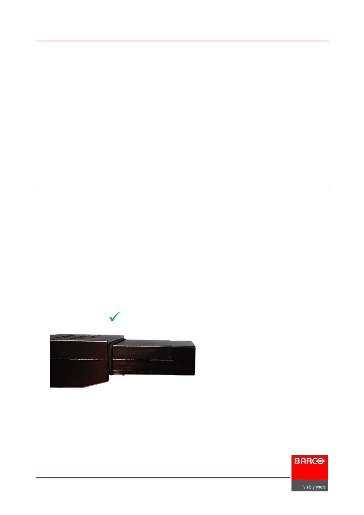
Seeimage1-1foranexampleofanundamagedcableend. Seeimage1-2foranexample
of a damaged cable e nd. The arrow in image 1-2 indicates where the shield has been bent
downwards, because of improper insertion. See image 1-3 for an example of the c able
latch hitting the connector. See image 1-4 for an example of incomplete insertion of the
cable into the Link Card connector.
Image 1-1
Undamaged cable end
Barco Inc, Image Processing
3078 Prospect Park Drive, Rancho Cordova, CA , 95670, USA
www.barco.com
Page 1 of 4
Barco service bulletin
Image 1-2
Damaged cable end
The arrow in image 1-2 indicates where the shield has been bent downwards, because of
improper insertion.
Image 1-3
Cable latch hitting connector
The arrow labeled “1” in image 1-3 indicates where the latch of the cable connector has hit
the edge of the Link Card connector. The arrows labeled “2” show the holes into which the
latch should t. See image 1-7 for an example of a properly latched cable and connector.
InfoT: 1294
Page 2 of 4
Barco service bulletin
Image 1-4
Incomplete insertion 5 mm
In image 1-4 about 5 mm of the end of the cable is still exposed; this is about the width of
four dimes.
It is at about the 5–mm point that the sheet metal on the cable can wedge into the con-
nector. When the cable wedges into the connector, the cable stops unless it is pushed hard
(greater than 2 pounds of force). The cable s hould slide sm
oothly, until the latches on the
cable come into contact with the connector itself, a nd the cable is in the position seen in
image 1-5 and image 1-7.
Solution
Follow the instructions in this document to help make sure that the cable is properly inserted
into the connector on each Link Card.
Scope
This procedure applies to all Link Cards on a
ll E2 series and S3-4K series presentation
switchers.
1.2 Properly connecting the Link Card cable
Connect the cable to the Link Card
1. Fully insert the cable into the connector on the Link Card.
The CXP connection is keyed. A groove on the cable-end connector guides a pin on the
Link Card connector.
(The Link Card connector shown in image 1-5 is shown as a component, not inserted on
aLinkCard.)
Page 3 of 4
InfoT: 1294
Barco service bulletin
Image 1-5
Fully inserted cable
2. If the cable resists full insertion, pull the cable slightly back toward the release, rotate it
counterclockwise, and reinsert it.
The arrow labeled “1” in image 1-6 shows the release. The c urved ar
row shows the
counterclockwise rotation.
Image 1-6
Direction of rotation
3. Make sure that the latch is properly engaged.
See image 1-7 for an example of a properly latched cable and connector.
Image 1-7
Cable and con n e ctor latched
InfoT: 1294 Page 4 of 4
  • Page 1 1
  • Page 2 2
  • Page 3 3
  • Page 4 4

Barco E2-Tri-Combo Owner's manual

Type
Owner's manual

Barco E2-Tri-Combo is a versatile presentation switcher designed to handle a variety of signal types, including analog and digital video, audio, and control signals. It features three independent inputs, each with its own scaler and format converter, allowing you to connect multiple sources and display them simultaneously on a single display. The switcher also includes a built-in multi-viewer that allows you to monitor all three inputs simultaneously on a single screen.

Ask a question and I''ll find the answer in the document

Finding information in a document is now easier with AI