Page is loading ...

Installation 2
Wiring Connections 2
Thermostat Quick Reference 3
Installer Configuration Menu 4
Operating Your Thermostat 7
Programming 7
Troubleshooting 11
www.white-rodgers.comwww.white-rodgers.com
www.white-rodgers.comwww.white-rodgers.com
www.white-rodgers.com
Big Blue Universal Thermostat withBig Blue Universal Thermostat with
Big Blue Universal Thermostat withBig Blue Universal Thermostat with
Big Blue Universal Thermostat with
Automatic Heat/Cool Changeover OptionAutomatic Heat/Cool Changeover Option
Automatic Heat/Cool Changeover OptionAutomatic Heat/Cool Changeover Option
Automatic Heat/Cool Changeover Option
PART NO. 37-6753CPART NO. 37-6753C
PART NO. 37-6753CPART NO. 37-6753C
PART NO. 37-6753C
Replaces 37-6753B
0904
Single Stage, Multi-Stage, Heat PumpSingle Stage, Multi-Stage, Heat Pump
Single Stage, Multi-Stage, Heat PumpSingle Stage, Multi-Stage, Heat Pump
Single Stage, Multi-Stage, Heat Pump
Installation and Operating Instructions for Model:Installation and Operating Instructions for Model:
Installation and Operating Instructions for Model:Installation and Operating Instructions for Model:
Installation and Operating Instructions for Model:
APPLICATIONSAPPLICATIONS
APPLICATIONSAPPLICATIONS
APPLICATIONS
DescriptionDescription
DescriptionDescription
Description
Heat Pump (No Aux. or Emergency Heat) Yes
Heat Pump (with Aux. or Emergency Heat) Yes
Systems with up to 3 Stages Heat, 2 Stages Cool Yes
Heat Only Systems Yes
Millivolt Heat Only Systems – Floor or Wall Furnaces Yes
Cool Only Systems Yes
Gas or Oil Heat Yes
Electric Furnace Yes
Hydronic (Hot Water) Zone Heat – 2 Wires Yes
Hydronic (Hot Water) Zone Heat – 3 Wires Yes
Wired Remote Temperature Sensor (Indoor/Outdoor) Yes
Dual Fuel Feature (Heat Pump Mode) Yes
THERMOSTAT APPLICATION GUIDETHERMOSTAT APPLICATION GUIDE
THERMOSTAT APPLICATION GUIDETHERMOSTAT APPLICATION GUIDE
THERMOSTAT APPLICATION GUIDE
1F95-1277 Touchscreen Thermostat1F95-1277 Touchscreen Thermostat
1F95-1277 Touchscreen Thermostat1F95-1277 Touchscreen Thermostat
1F95-1277 Touchscreen Thermostat
SPECIFICATIONSSPECIFICATIONS
SPECIFICATIONSSPECIFICATIONS
SPECIFICATIONS
Electrical Rating:
Battery Power . . . . . . . . . . . . . . . . . . . . . . . . . mV to 30 VAC, NEC Class II, 50/60 Hz or DC
Input-Hardwire . . . . . . . . . . . . . . . . . . . . . . . . 20 to 30 VAC
Terminal Load . . . . . . . . . . . . . . . . . . . . . . . . . . . . 1.5A per terminal, 2.5A maximum all terminals combined
Setpoint Range . . . . . . . . . . . . . . . . . . . . . . . . . . . 45 to 99°F (7 to 32°C)
Differential (Single Stage) . . . . . . . . . . . . . . . . . . . Heat 0.6°F; Cool 1.2°F
Differential (Multi-Stage) . . . . . . . . . . . . . . . . . . . . Heat 0.6°F; Cool 1.2°F
Differential (Heat Pump) . . . . . . . . . . . . . . . . . . . . Heat 1.2°F; Cool 1.5°F
Operating Ambient . . . . . . . . . . . . . . . . . . . . . . . . . 32°F to +105°F (0 to +41°C)
Operating Humidity . . . . . . . . . . . . . . . . . . . . . . . . 90% non-condensing max.
Shipping Temperature Range . . . . . . . . . . . . . . . . -4 to +150°F (-20 to +65°C)
Dimensions Thermostat . . . . . . . . . . . . . . . . . . . . . 4.6"H x 5.9"W x 1.2"D
To prevent electrical shock and/or equipment dam-To prevent electrical shock and/or equipment dam-
To prevent electrical shock and/or equipment dam-To prevent electrical shock and/or equipment dam-
To prevent electrical shock and/or equipment dam-
age, disconnect electric power to system at main fuseage, disconnect electric power to system at main fuse
age, disconnect electric power to system at main fuseage, disconnect electric power to system at main fuse
age, disconnect electric power to system at main fuse
or circuit breaker box until installation is complete.or circuit breaker box until installation is complete.
or circuit breaker box until installation is complete.or circuit breaker box until installation is complete.
or circuit breaker box until installation is complete.
CAUTION
!
ATTENTION: MERCURY NOTICEATTENTION: MERCURY NOTICE
ATTENTION: MERCURY NOTICEATTENTION: MERCURY NOTICE
ATTENTION: MERCURY NOTICE
This product does not contain mercury. However, this
product may replace a product that contains mercury.
Mercury and products containing mercury must not be
discarded in household trash. Do not touch any spilled
mercury. Wearing non-absorbent gloves, clean up any
spilled mercury and place in a sealed container. For proper
disposal of a product containing mercury or a sealed
container of spilled mercury, place it in a suitable shipping
container. Refer to
wwwwww
wwwwww
www
.w.w
.w.w
.w
hite-rhite-r
hite-rhite-r
hite-r
odgodg
odgodg
odg
erer
erer
er
ss
ss
s
.com .com
.com .com
.com for location to
send the product containing mercury.
IndexIndex
IndexIndex
Index
PagePage
PagePage
Page
ModelModel
ModelModel
Model
Programming ChoicesProgramming Choices
Programming ChoicesProgramming Choices
Programming Choices
1F95-12771F95-1277
1F95-12771F95-1277
1F95-1277
Non-Programmable 5/1/1 Day 7 Day
Save these instructions for future use!Save these instructions for future use!
Save these instructions for future use!Save these instructions for future use!
Save these instructions for future use!
FAILURE TO READ AND FOLLOW ALL INSTRUCTIONSFAILURE TO READ AND FOLLOW ALL INSTRUCTIONS
FAILURE TO READ AND FOLLOW ALL INSTRUCTIONSFAILURE TO READ AND FOLLOW ALL INSTRUCTIONS
FAILURE TO READ AND FOLLOW ALL INSTRUCTIONS
CAREFULLY BEFORE INSTALLING OR OPERATING THISCAREFULLY BEFORE INSTALLING OR OPERATING THIS
CAREFULLY BEFORE INSTALLING OR OPERATING THISCAREFULLY BEFORE INSTALLING OR OPERATING THIS
CAREFULLY BEFORE INSTALLING OR OPERATING THIS
CONTROL COULD CAUSE PERSONAL INJURY AND/ORCONTROL COULD CAUSE PERSONAL INJURY AND/OR
CONTROL COULD CAUSE PERSONAL INJURY AND/ORCONTROL COULD CAUSE PERSONAL INJURY AND/OR
CONTROL COULD CAUSE PERSONAL INJURY AND/OR
PROPERTY DAMAGE.PROPERTY DAMAGE.
PROPERTY DAMAGE.PROPERTY DAMAGE.
PROPERTY DAMAGE.

2
2 "AA" Batteries
WIRING CONNECTIONSWIRING CONNECTIONS
WIRING CONNECTIONSWIRING CONNECTIONS
WIRING CONNECTIONS
Refer to equipment manufacturers' instructions for specific
system wiring information. After wiring, see CONFIGURA-
TION section for proper thermostat configuration.
For wiring diagrams, see 37-6808.
Wiring diagrams shown are for typical systems and describe
the thermostat terminal functions.
WARNING
!
Thermostat installation and all components of theThermostat installation and all components of the
Thermostat installation and all components of theThermostat installation and all components of the
Thermostat installation and all components of the
control system shall conform to Class II circuits percontrol system shall conform to Class II circuits per
control system shall conform to Class II circuits percontrol system shall conform to Class II circuits per
control system shall conform to Class II circuits per
the NEC code.the NEC code.
the NEC code.the NEC code.
the NEC code.
INSTALLATIONINSTALLATION
INSTALLATIONINSTALLATION
INSTALLATION
Battery LocationBattery Location
Battery LocationBattery Location
Battery Location
2 "AA" alkaline batteries are included in the thermostat at
the factory with a battery tag to prevent power drainage.
Remove the battery tag to engage the batteries.
To replace batteries, set system to
OFFOFF
OFFOFF
OFF, remove thermostat
from wall and install the batteries in the rear along the top of
the thermostat (see Figure 1). For best results, use a
premium brand "AA" alkaline battery such as Duracell
®
or
Energizer
®
.
Remove Old ThermostatRemove Old Thermostat
Remove Old ThermostatRemove Old Thermostat
Remove Old Thermostat
A standard heat/cool thermostat consists of three basic parts:
1. The cover, which may be either a snap-on or hinge type.
2. The base, which is removed by loosening all captive screws.
3. The switching subbase, which is removed by unscrewing
the mounting screws that hold it on the wall or adapter
plate.
BefBef
BefBef
Bef
oror
oror
or
e re r
e re r
e r
emoemo
emoemo
emo
ving wirving wir
ving wirving wir
ving wir
es fres fr
es fres fr
es fr
om old therom old ther
om old therom old ther
om old ther
mostamosta
mostamosta
mosta
t,t,
t,t,
t,
label each wire with the terminal designation fromlabel each wire with the terminal designation from
label each wire with the terminal designation fromlabel each wire with the terminal designation from
label each wire with the terminal designation from
which it was attachedwhich it was attached
which it was attachedwhich it was attached
which it was attached. Disconnect the wires from the old
thermostat one at a time.
Do not let wirDo not let wir
Do not let wirDo not let wir
Do not let wir
es fes f
es fes f
es f
all bacall bac
all bacall bac
all bac
k intok into
k intok into
k into
the wallthe wall
the wallthe wall
the wall.
Installing New ThermostatInstalling New Thermostat
Installing New ThermostatInstalling New Thermostat
Installing New Thermostat
1. Pull the thermostat body off the thermostat base. Forcing
or prying on the thermostat will cause damage to the unit.
2. Place base over hole in wall and mark mounting hole
locations on wall using base as a template.
3. Move base out of the way. Drill mounting holes. If you
are using existing mounting holes and the holes drilled
are too large and do not allow you to tighten base snug-
ly, use plastic screw anchors to secure the base.
4. Fasten base snugly to wall using mounting holes shown
in Figure 1 and two mounting screws. Leveling is for
appearance only and will not affect thermostat operation.
5. Connect wires to terminal block on base using
appropriate wiring schematic (see diagram sheet
37-6808).
6. Push excess wire into wall and plug hole with a fire re-
sistant material (such as fiberglass insulation) to prevent
drafts from affecting thermostat operation.
7. Carefully line the thermostat up with the base and snap
into place.
Terminal DesignationTerminal Designation
Terminal DesignationTerminal Designation
Terminal Designation
DescriptionDescription
DescriptionDescription
Description
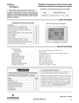
B . . . . . . . . . . . . . . . . . . Changeover valve for heat pump energized constantly in heating
O . . . . . . . . . . . . . . . . . . Changeover valve for heat pump energized constantly in cooling and off
Y2 . . . . . . . . . . . . . . . . . . 2nd Stage Compressor
Y . . . . . . . . . . . . . . . . . . Compressor Relay
G . . . . . . . . . . . . . . . . . . Fan Relay
RC . . . . . . . . . . . . . . . . . . Power for Cooling
RH . . . . . . . . . . . . . . . . . . Power for Heating
C . . . . . . . . . . . . . . . . . . Common wire from secondary side of cooling (Optional). Required for fault indication,
continuous backlight operation or remote temperature sensor operation
L . . . . . . . . . . . . . . . . . . Malfunction indicator for systems with malfunction connection
6 . . . . . . . . . . . . . . . . . . Powered closed 3rd wire for 3-wire zone valve
W/E . . . . . . . . . . . . . . . . . Heat Relay/Emergency Heat Relay (Stage 1)
W2 . . . . . . . . . . . . . . . . . . 2nd Stage Heat (3rd Stage Heat in HP2)
Blank . . . . . . . . . . . . . . . . . Blank
- . . . . . . . . . . . . . . . . . . . Common (DC) for wired remote temperature sensor
S . . . . . . . . . . . . . . . . . . Frequency signal from remote temperature sensor
+ . . . . . . . . . . . . . . . . . . Power (DC) to remote temperature sensor
TERMINAL DESIGNATION DESCRIPTIONSTERMINAL DESIGNATION DESCRIPTIONS
TERMINAL DESIGNATION DESCRIPTIONSTERMINAL DESIGNATION DESCRIPTIONS
TERMINAL DESIGNATION DESCRIPTIONS
Mounting
Hole
Mounting
Hole
Place Level
across
Mounting Tabs
(for appearance only)
Place Level
across
Mounting Tabs
(for appearance only)
+
S
-
W/E
6
L
Y2
W2
Figure 1 – Thermostat Base Multi-Stage 1F95-1277Figure 1 – Thermostat Base Multi-Stage 1F95-1277
Figure 1 – Thermostat Base Multi-Stage 1F95-1277Figure 1 – Thermostat Base Multi-Stage 1F95-1277
Figure 1 – Thermostat Base Multi-Stage 1F95-1277
Rear view of thermostatRear view of thermostat
Rear view of thermostatRear view of thermostat
Rear view of thermostat

3
Time of Day
Day of Week
Room
Temperature
System
Switch
Fan
Switch
Indicates when
thermostat is calling
for Heat or Cool
Battery Level Indicator
Indicating the current power level
of the 2 “AA” batteries.
Full power remaining.
Half power remaining.
Change The batteries should be replaced at this time.
Menu key for entering
different modes such as
Cleaning, Configuration, Set
Time and Set Schedule
Enters comfort
temperature settings
into the schedule
Temperature
UP/Down used for
modifying set point
as well as to
navigating the menus
Set Temperature
THERMOSTAT QUICK REFERENCETHERMOSTAT QUICK REFERENCE
THERMOSTAT QUICK REFERENCETHERMOSTAT QUICK REFERENCE
THERMOSTAT QUICK REFERENCE
Home Screen DescriptionHome Screen Description
Home Screen DescriptionHome Screen Description
Home Screen Description
Figure 2 – Home Screen DisplayFigure 2 – Home Screen Display
Figure 2 – Home Screen DisplayFigure 2 – Home Screen Display
Figure 2 – Home Screen Display
13
"
System OnSystem On
System OnSystem On
System On" indicates when heating or cooling stage
is energized. "
+2+2
+2+2
+2" also indicates when a second stage
is energized.
14
"
CopyCopy
CopyCopy
Copy" indicates the copy program feature is being
used during programming.
12
"
Call For ServiceCall For Service
Call For ServiceCall For Service
Call For Service" indicates a fault in the heating/
cooling system. It does not indicate a fault in the
thermostat.
11
The words "
Hold AtHold At
Hold AtHold At
Hold At" are displayed when the thermo-
stat is in the
HOLD HOLD
HOLD HOLD
HOLD mode. "
Temporary Hold AtTemporary Hold At
Temporary Hold AtTemporary Hold At
Temporary Hold At" is
displayed when the thermostat is in a temporary
HOLDHOLD
HOLDHOLD
HOLD
mode.
10
"
HoursHours
HoursHours
Hours" and "
DaysDays
DaysDays
Days" displays during steps in installer
configuration.
9
"
Hold UntilHold Until
Hold UntilHold Until
Hold Until" indicates the time when a temporary hold
period will end.
8
Used in programming to set time and in configuration
menu to change selections.
7
CLEAN DISPLAY button allows 30 seconds to wipe off
the display or ADVANCE DAY button for programming.
6
COPY button or INSTALLER CONFIG button.
5
Displays "
Change FilterChange Filter
Change FilterChange Filter
Change Filter" when the system has run
for the programmed filter time period as a reminder
to change or clean your filter.
2
Indicates period of day being programmed.
3
RUN SCHEDULE (run program) button.
4
SET TIME button or HOLD temperature button.
1
Displays and "
Keypad LockoutKeypad Lockout
Keypad LockoutKeypad Lockout
Keypad Lockout" when in keypad
lockout mode.
Displays and "
Temperature LimitTemperature Limit
Temperature LimitTemperature Limit
Temperature Limit" and "
KeypadKeypad
KeypadKeypad
Keypad
LockoutLockout
LockoutLockout
Lockout" when limited range is activated and locked.
Displays only "
Temperature LimitTemperature Limit
Temperature LimitTemperature Limit
Temperature Limit" when limited range
is activated.
Programming and Configuration ItemsProgramming and Configuration Items
Programming and Configuration ItemsProgramming and Configuration Items
Programming and Configuration Items
Figure 3 – Programming & Configuration ItemsFigure 3 – Programming & Configuration Items
Figure 3 – Programming & Configuration ItemsFigure 3 – Programming & Configuration Items
Figure 3 – Programming & Configuration Items
15
A steady "
Cool SavingsCool Savings
Cool SavingsCool Savings
Cool Savings" display indicates the feature
is enabled in the installer menu. A flashing "
CoolCool
CoolCool
Cool
SavingsSavings
SavingsSavings
Savings" display indicates the feature is active.
16
"
RemoteRemote
RemoteRemote
Remote" indicates that the indoor remote temperature
sensor, is being accessed. "
Outdoor RemoteOutdoor Remote
Outdoor RemoteOutdoor Remote
Outdoor Remote" indi-
cates the outdoor remote temperature sensor is being
accessed.
16
15
14
13
12
11
10
9
8
76
54
3
2
1

4
CONFIGURATION MENUCONFIGURATION MENU
CONFIGURATION MENUCONFIGURATION MENU
CONFIGURATION MENU
Non- Displayed Press or
Program- Program- Press (Factory to select from
mable mable Button Default) listed options Comments
1 1 MS 2 HP 1, HP 2, SS 1 Selects Multi-Stage (MS 2, No Heat Pump), Heat Pump 1
(HP 1, 1 compressor), Heat Pump 2 (HP 2, 2 compressor
or 2 speed compressor), or Single Stage.
22
(ELE) GAS GAS setting: furnace controls blower.
ELE setting: thermostat controls blower.
33
Days, (
77
77
7)
P P
P P
P
55
55
5-1-1 or
00
00
0 Programs per week. (0 = non-programmable)
4NA
PSPS
PSPS
PS (
44
44
4)
22
22
2 Program periods per day.
4 = Morning, Day, Evening, Night
2 = Day, Night
54
Cool-Off- Cool-Off-Heat, System switch configuration in non heat pump mode.
Heat-Auto Off-Heat, Cool-Off
Cool-Off-Heat- Cool-Off-Heat-Emer, System switch configuration, heat pump mode.
Emer-Auto Off-Heat-Emer, Cool-Off
6NA
E E
E E
E (On)
OFFOFF
OFFOFF
OFF Selects Energy Management Recovery, E (with programming option on)
75
Cr, Heat (FA) SL Selects Adjustable Anticipation, cycle rate, Heat
86
Cr, Cool (FA) SL Selects Adjustable Anticipation, cycle rate, Cool
97
Cr/AU, Emer (FA) SL Selects Adjustable Anticipation, cycle rate auxiliary, (This item is
only to appear if HP 1 or HP 2 is selected above).
10 8
CL CL
CL CL
CL (OFF) On Selects Compressor Lockout.
11 9
dL dL
dL dL
dL (On) OFF Selects Continuous Display backlight & intensity.
12 10
dL dL
dL dL
dL (LO) HI Selects Backlight Intensity.
13 11
0 4, LO to 4, HI Selects Adjustable Ambient Temperature Display [range -4 (LO) to
+4 (HI)].
14 12
°
FF
FF
F°
CC
CC
C Selects °F/°C Display (temperature units in Fahrenheit or Celsius).
15 13
b b
b b
b (On) OFF Selects audible Beeper On/Off.
16 14
dS dS
dS dS
dS (On) OFF Selects Daylight Saving Time calculation.
17 15
ASAS
ASAS
AS, Heat (On) OFF Selects Automatic Schedule for comfort temperature Programming,
heat mode.
18 16
ASAS
ASAS
AS, Cool (On) OFF Selects Automatic Schedule for comfort temperature Programming,
cool mode.
19 17
CSCS
CSCS
CS, (OFF) 1-2-3-4-5-6 Selects Cool Saving Feature & amount.
Cool Savings
20 18
HLHL
HLHL
HL, Heat (99) 62-98 TEMPERATURE LIMIT, HEAT (max. heat set point).
21 19
LLLL
LLLL
LL, Cool (45) 46-82 TEMPERATURE LIMIT, COOL (min. cool set point).
22 20
OFF,
L L
L L
L (total),
P P
P P
P (partial), Selects Keypad Lockout.
Keypad LockoutKeypad Lockout
Keypad LockoutKeypad Lockout
Keypad Lockout
Temperature LimitTemperature Limit
Temperature LimitTemperature Limit
Temperature Limit
(limited temperature range)
000 001-999 Selects Keypad Lockout Combination (active only if keypad Lockout
is selected).
23 21
FS, Heat (On) OFF Fast second stage of heat (not available if SS1 is selected above).
24 22
FS, Cool (On) OFF Fast second stage of cool (not available if SS1 or HP1 is selected
above).
25 23
Remote (OFF) On Remote temperature sensor, enable/disable.
In, Remote Outdoor Remote Remote temperature sensor (Indoor/Outdoor).
LS (On) OFF Local temp. Sensor enable/disable (only when Indoor Remote is
selected On).
26 24
dF dF
dF dF
dF (5) 5-50 Selects Dual Fuel Feature & set point (in Fahrenheit) (applicable only
when HP1 or HP2 is selected).
Cd Cd
Cd Cd
Cd (60) 0-99 Selects Compressor delay in seconds (only when
dF dF
dF dF
dF is selected >5).
27 25
Change Filter On Selects Change filter feature
(OFF)
200 Hours 25-1975 (in increments Change filter, duration hours.
of 25 hours)
INSTALLER/CONFIGURATION MENUINSTALLER/CONFIGURATION MENU
INSTALLER/CONFIGURATION MENUINSTALLER/CONFIGURATION MENU
INSTALLER/CONFIGURATION MENU
To enter the menu: Press the
MenMen
MenMen
Men
u u
u u
u touch key. Press and hold for 5 seconds the
Installer ConfigInstaller Config
Installer ConfigInstaller Config
Installer Config touch key. This displays
menu item #1 in the table below. Press
to advance to the next menu item or to return to a previous menu item. Press
or to change a menu item.
Menu
Reference
Number
1
2
3
4
5
6
7
8
9
10
11
12
13
14
15
16
17
18
19
20
21
22
23
24
25
26
27

5
INSTALLER/CONFIGURATION MENUINSTALLER/CONFIGURATION MENU
INSTALLER/CONFIGURATION MENUINSTALLER/CONFIGURATION MENU
INSTALLER/CONFIGURATION MENU
11)
Select Continuous Backlight Select Continuous Backlight
Select Continuous Backlight Select Continuous Backlight
Select Continuous Backlight – In low lighting condi-
tions, display backlight improves the display contrast.
When
CC
CC
C terminal is connected, selecting dL On will turn
the backlight on continuously. Selecting dL Off will turn
the backlight on momentarily after any key is pressed.
When
CC
CC
C terminal is not powered (battery only), dL On
enables the momentary backlight whenever a key is
pressed.
12)
Select BacSelect Bac
Select BacSelect Bac
Select Bac
klight Intensityklight Intensity
klight Intensityklight Intensity
klight Intensity – This thermostat has the
ability to provide two selectable intensities of the back-
light: HI and LO. Using
or touch keys you can
toggle the selection between HI and LO.
13)
Select Temperature Display Adjustment 4 LO to 4 HISelect Temperature Display Adjustment 4 LO to 4 HI
Select Temperature Display Adjustment 4 LO to 4 HISelect Temperature Display Adjustment 4 LO to 4 HI
Select Temperature Display Adjustment 4 LO to 4 HI
This allows you to adjust the room temperature display
by an amount in the range of -4°F to +4°F in 1° steps by
using the
or touch keys. Your thermostat was
accurately calibrated at the factory, however you have the
option to change the display temperature value to match
your previous thermostat, if you so prefer.
14)
Select °F or °C RSelect °F or °C R
Select °F or °C RSelect °F or °C R
Select °F or °C R
eadouteadout
eadouteadout
eadout – Select the desired temper-
ature unit by pressing
or . Factory default is °F.
15)
Select Select
Select Select
Select
AA
AA
A
udio Prudio Pr
udio Prudio Pr
udio Pr
ompting (Beeompting (Bee
ompting (Beeompting (Bee
ompting (Bee
per) On or Ofper) On or Of
per) On or Ofper) On or Of
per) On or Of
ff
ff
f
– Factory
default setting is on (
bb
bb
b
,,
,,
,
On On
On On
On). If you wish to turn off the
beeper select OFF.
16)
Select DaSelect Da
Select DaSelect Da
Select Da
ylight Saylight Sa
ylight Saylight Sa
ylight Sa
ving ving
ving ving
ving
Time CalculaTime Calcula
Time CalculaTime Calcula
Time Calcula
tiontion
tiontion
tion – This feature
will allow the thermostat to calculate the DST automati-
cally and apply it to the Real Time Clock display. Default
On. Use
or touch keys to select the feature, OFF.
17 & 18)
Select Select
Select Select
Select
AA
AA
A
utomautoma
utomautoma
utoma
tic Sctic Sc
tic Sctic Sc
tic Sc
hedulehedule
hedulehedule
hedule – This feature allows
programming a “Comfort Temperature” into all program
periods with the
AA
AA
A
uto Scuto Sc
uto Scuto Sc
uto Sc
hedulehedule
hedulehedule
hedule key. When
HeaHea
HeaHea
Hea
t t
t t
t
ASAS
ASAS
AS (for
Heat mode) or
Cool Cool
Cool Cool
Cool
ASAS
ASAS
AS (for Cool mode) is selected
OnOn
OnOn
On,
the Auto Schedule feature is ready to be set.
OfOf
OfOf
Of
ff
ff
f
indicates that the feature is not ready to be used or a
“Comfort Temperature is already set. See Auto Schedule
in Programming section.
19)
Select Cool SaSelect Cool Sa
Select Cool SaSelect Cool Sa
Select Cool Sa
vings™vings™
vings™vings™
vings™: With Cool Savings™ enabled,
the thermostat will make small adjustments to the
setpoint temperature during periods of high demand to
reduce AC system running time and save energy. When
the cooling system has been running for more than 20
minutes, humidity in the home will be lower and a higher
temperature will feel comfortable. After 20 minutes of run
time, the thermostat will start increasing the setpoint
temperature in steps of less than one degree as the
system continues to run. These adjustments will eventu-
ally cause the system to satisfy the thermostat to turn the
system off and reduce the energy consumption. When
the Cool Savings™ feature is active and making adjust-
ments, the display will flash “
Cool SaCool Sa
Cool SaCool Sa
Cool Sa
vings”vings”
vings”vings”
vings”. The amount
of the adjustments to the setpoint temperature is depen-
dent on the Cool Savings™ value that is set, 1 being the
least adjustment and 6 being the most adjustment. With
this feature set to OFF, no change will occur when the AC
system is continuously running during the periods of high
demand. Periods of high demand will normally occur
during the late afternoon and early evening on the hottest
days of the summer. As demand lessens the adjustments
to setpoint temperature are reversed until setpoint
temperature returns to normal and
“Cool Sa“Cool Sa
“Cool Sa“Cool Sa
“Cool Sa
vings”vings”
vings”vings”
vings” no
longer flashes.
1) This control can be configured for:
MS2 – Multi-Stage System (2 heat/2 cool)
HP1 – Heat Pump with one stage of compressor
(2 heat/1 cool)
HP2 – Heat Pump with two stage compressor or two
compressor system, Gas or Electric backup; (Dual Fuel
see menu item 26) (3 heat/2 cool)
SS1 – Single Stage System (3 wire zone see wiring
diagram 37-6808A)
2) GAS or Electric (ELE) fan operation. If the heating
system requires the thermostat to energize the fan,
select ELE. Select GAS if the heating system energizes
the fan on a call for heat.
Note:Note:
Note:Note:
Note:
R R
R R
R
esetting the theresetting the ther
esetting the theresetting the ther
esetting the ther
mo-mo-
mo-mo-
mo-
stat switches the option to ELE.stat switches the option to ELE.
stat switches the option to ELE.stat switches the option to ELE.
stat switches the option to ELE.
3)
PrPr
PrPr
Pr
oo
oo
o
gg
gg
g
rr
rr
r
ams per wams per w
ams per wams per w
ams per w
eekeek
eekeek
eek – This control can be configured for
7 independent day or 5/1/1 day programming or non-
programmable modes. Default is 7-day mode. The
display indicates "
7 Da7 Da
7 Da7 Da
7 Da
ysys
ysys
ys" as default. Other options "
55
55
5
DaDa
DaDa
Da
ysys
ysys
ys" or "
0 Da0 Da
0 Da0 Da
0 Da
ysys
ysys
ys" can be selected by pressing touch
keys,
or . If "
0 Da0 Da
0 Da0 Da
0 Da
ysys
ysys
ys" is selected for non-program-
mable mode, the step for EMR will be skipped, as this
feature will not be available in this mode.
4)
Program Steps per dayProgram Steps per day
Program Steps per dayProgram Steps per day
Program Steps per day – This control can be config-
ured for 4 or 2 program steps per day. Default is "
4 PS4 PS
4 PS4 PS
4 PS"
and can be toggled between 4 PS and 2 PS by pressing
the
or touch keys.
5)
System Switch Configuration (MS2/SS1)System Switch Configuration (MS2/SS1)
System Switch Configuration (MS2/SS1)System Switch Configuration (MS2/SS1)
System Switch Configuration (MS2/SS1) – This
thermostat is configured for Heat and Cool with Auto
changeover default (Cool-Off-Heat-Auto). Can be
configured as Heat & Cool (Cool-Off-Heat), or Heat Only
(Off-Heat), or Cool Only (Cool-Off).
When the control is in heat pump configuration (
HP1HP1
HP1HP1
HP1/
HP2HP2
HP2HP2
HP2), the system switch configuration will have an
additional mode available namely,
Emer Emer
Emer Emer
Emer for
EmerEmer
EmerEmer
Emer
gg
gg
g
encenc
encenc
enc
yy
yy
y
ModeMode
ModeMode
Mode.
6)
Energy Management Recovery (EMR) Energy Management Recovery (EMR)
Energy Management Recovery (EMR) Energy Management Recovery (EMR)
Energy Management Recovery (EMR) – (this step is
skipped if configured as non-programmable).
When set to "On" causes the thermostat to start heating
or cooling early to make the building temperature reach
the program setpoint at the time you specify.
ExampleExample
ExampleExample
Example: Let us say, the heating program is 65°F at
night and 70° at 7 AM. If the building temperature is 65°F,
the difference is 5°F. Allowing 5 minutes per °F rise, the
thermostat setpoint will change to 70° at 6:35 AM.
Cooling allows more time per °F, because it takes
longer to reach temperature.
7, 8 & 9)
CyCy
CyCy
Cy
cc
cc
c
le Rle R
le Rle R
le R
aa
aa
a
te Selectionte Selection
te Selectionte Selection
te Selection – The factory default setting
is fast cycle (FA Cr) in all modes (Heat, Cool, Emer). To
slow cycling (SL, Cr), press touch keys
or toggle
between FA & SL. The cycle rates are as below different
selections:
ModeMode
ModeMode
Mode
Fast rateFast rate
Fast rateFast rate
Fast rate
Slow rateSlow rate
Slow rateSlow rate
Slow rate
Heat 0.6°F 1.2°F
Cool 1.2°F 1.7°F
Emer 1.2°F 1.7°F
10)
Select Compressor Lockout (CL)Select Compressor Lockout (CL)
Select Compressor Lockout (CL)Select Compressor Lockout (CL)
Select Compressor Lockout (CL) – Selecting CL On
will cause the thermostat to wait 5 minutes between
cooling cycles. This is intended to help protect the
compressor from short cycling. Some of the newer
compressors have already got a time delay built in and
do not require this feature to be activated in the thermo-
stat. Your compressor manufacturer can tell you if
this lockout feature is already present in their system.
When the thermostat compressor time delay is activated,
it will flash the set point for up to five minutes.

6
20)
HeaHea
HeaHea
Hea
t t
t t
t
TT
TT
T
emperemper
emperemper
emper
aa
aa
a
turtur
turtur
tur
e Limit Re Limit R
e Limit Re Limit R
e Limit R
angang
angang
ang
ee
ee
e – This feature adjusts
the highest setpoint temperature for heat. The default
setting is 99°F. It can be changed between 62°F and
98°F by pressing the
or key. The "
tempertemper
tempertemper
temper
aa
aa
a
turtur
turtur
tur
ee
ee
e
limitlimit
limitlimit
limit" icon will be displayed to the left of your setpoint
temperature when using this feature. The "
tempertemper
tempertemper
temper
aa
aa
a
turtur
turtur
tur
ee
ee
e
limitlimit
limitlimit
limit" icon will flash if an attempt is made to adjust the
temperature beyond the range selected.
21)
Cool Cool
Cool Cool
Cool
TT
TT
T
emperemper
emperemper
emper
aa
aa
a
turtur
turtur
tur
e Limit Re Limit R
e Limit Re Limit R
e Limit R
angang
angang
ang
ee
ee
e – This feature adjusts
the lowest setpoint temperature for cool. The default
setting is 45°F. It can be changed between 46°F and
82°F by pressing the
or key. The "
tempertemper
tempertemper
temper
aa
aa
a
turtur
turtur
tur
ee
ee
e
limitlimit
limitlimit
limit" icon will be displayed to the left of your setpoint
temperature when using this feature. The "
tempertemper
tempertemper
temper
aa
aa
a
turtur
turtur
tur
ee
ee
e
limitlimit
limitlimit
limit" icon will flash if an attempt is made to adjust the
temperature beyond the range selected.
22)
KK
KK
K
ee
ee
e
ypad Locypad Loc
ypad Locypad Loc
ypad Loc
kk
kk
k
outout
outout
out – This step allows you to select the
type of lockout or limited range security required. If no
lockout or limited range security is required, press
to
advance the menu.
Three security settings are available in this menu item.
Use the
or keys to select the lockout desired.
Lockout selections are:
"
KK
KK
K
ee
ee
e
ypad Locypad Loc
ypad Locypad Loc
ypad Loc
kk
kk
k
out out
out out
out and
LL
LL
L" = Total Lockout. Total Lockout
locks all keys.
"
KK
KK
K
ee
ee
e
ypad Locypad Loc
ypad Locypad Loc
ypad Loc
kk
kk
k
out out
out out
out and
PP
PP
P" = Partial Lockout. Partial Lock-
out allows only the
or keys to operate within your
set temperature limits.
"
TT
TT
T
emperemper
emperemper
emper
aa
aa
a
turtur
turtur
tur
e Limite Limit
e Limite Limit
e Limit/
KK
KK
K
ee
ee
e
ypad Locypad Loc
ypad Locypad Loc
ypad Loc
kk
kk
k
outout
outout
out" prevents
changing the temperature limits in the Configuration
Menu.
Keypad Lockout Combination Number SelectionKeypad Lockout Combination Number Selection
Keypad Lockout Combination Number SelectionKeypad Lockout Combination Number Selection
Keypad Lockout Combination Number Selection
Display will read "
OFFOFF
OFFOFF
OFF" "
KK
KK
K
ee
ee
e
ypad Locypad Loc
ypad Locypad Loc
ypad Loc
kk
kk
k
outout
outout
out".
Skip this step and continue through the configuration
menu items 19 thru 22 if you require an Air Filter Change
out indicator or Humidifier Pad Change out indicator by
pressing the
button to advance.
Return to this point when you are ready to start your
selected lock-out and continue by:
Pressing
or keys to select ON.
Press
. Display will read "
000000
000000
000".
Pressing
or keys to select your keypad lockout
combination number. Note: "
000000
000000
000" is not a valid
combination choice.
Record the number you select for future use.Record the number you select for future use.
Record the number you select for future use.Record the number you select for future use.
Record the number you select for future use.
Press
to exit the menu. The security feature you
select will start in 10 seconds. The system button will
remain active for 10 seconds to allow setting Heat, Off,
Cool or Auto.
INSTALLER/CONFIGURATION MENUINSTALLER/CONFIGURATION MENU
INSTALLER/CONFIGURATION MENUINSTALLER/CONFIGURATION MENU
INSTALLER/CONFIGURATION MENU
23 & 24)
Select FSelect F
Select FSelect F
Select F
ast Second Staast Second Sta
ast Second Staast Second Sta
ast Second Sta
gg
gg
g
e ON or OFFe ON or OFF
e ON or OFFe ON or OFF
e ON or OFF – In the run
mode, with the fast Heat feature enabled (FA Heat On), if
the Heat setpoint temperature is manually raised by 3°F
(2°C) or more above the actual temperature using
the
second stage will energize immediately. With FA OFF,
second stage will not energize until the setpoint tempera-
ture is 1°F or more above actual temperature for more
than ten minutes. The Fast Cool feature (FA Cool)
provides the same controls when the setpoint tempera-
ture is lowered.
25)
Select Remote Temperature SensorSelect Remote Temperature Sensor
Select Remote Temperature SensorSelect Remote Temperature Sensor
Select Remote Temperature Sensor – This control
allows one wired remote temperature sensor (indoor,
F145-1328, or outdoor, F145-1378) be connected to it
and indicates the measured temperature in clock digits.
This menu enables you to select the remote sensor and
also configure it as indoor or outdoor temperature sensor.
Factory default is off. Select
RR
RR
R
emote Onemote On
emote Onemote On
emote On and
RR
RR
R
emote inemote in
emote inemote in
emote in
(for indoor) or
Outdoor ROutdoor R
Outdoor ROutdoor R
Outdoor R
emoteemote
emoteemote
emote.
Local Local
Local Local
Local
TT
TT
T
emperemper
emperemper
emper
aa
aa
a
turtur
turtur
tur
e Sensor disae Sensor disa
e Sensor disae Sensor disa
e Sensor disa
bb
bb
b
lele
lele
le – This is applicable
only when indoor remote temperature sensor is enabled.
Factory default is
On LSOn LS
On LSOn LS
On LS. You can make it
OfOf
OfOf
Of
ff
ff
f
LS LS
LS LS
LS if you
desire by using
or touch keys.Then, only the
indoor remote temperature reading will be used for
control.
26)
Select Dual Fuel FSelect Dual Fuel F
Select Dual Fuel FSelect Dual Fuel F
Select Dual Fuel F
eaea
eaea
ea
turtur
turtur
tur
e and Setpointe and Setpoint
e and Setpointe and Setpoint
e and Setpoint – This feature is
applicable only in heat pump modes. An outside remote
sensor must also be installed. When the outside tem-
perature falls below the selected setpoint temperature,
dFdF
dFdF
dF, the thermostat will switch to gas heat and shut down
the compressor. Use the
or keys to select the
desired setpoint temperature in the range of 5 to 50.
Factory default is 5, which disables this feature. See
Dual Fuel Temperature and Setpoint in Programming
section.
Select ComprSelect Compr
Select ComprSelect Compr
Select Compr
essor Delaessor Dela
essor Delaessor Dela
essor Dela
yy
yy
y – When
dFdF
dFdF
dF is enabled, the
shut down of the compressor(s) is delayed for a time
period after the auxiliary stage is energized. This delay,
CdCd
CdCd
Cd, is factory set at 60, but can be set in the range of 0
to 99.
27)
Select ChangSelect Chang
Select ChangSelect Chang
Select Chang
e Filter Re Filter R
e Filter Re Filter R
e Filter R
un un
un un
un
TimeTime
TimeTime
Time – The thermostat
will display "
ChangChang
ChangChang
Chang
e Filtere Filter
e Filtere Filter
e Filter" after a set time of blower
operation. This is a reminder to change or clean your air
filter. This time can be set from 25 to 1975 hours in 25
hour increments. A selection of OFF will cancel this
feature. When "
ChangChang
ChangChang
Chang
e Filtere Filter
e Filtere Filter
e Filter" is displayed, you can
clear it by pressing Clean Display. In a typical application,
200 hours of run time is approximately 30 days.

7
OPERATING YOUR THERMOSTATOPERATING YOUR THERMOSTAT
OPERATING YOUR THERMOSTATOPERATING YOUR THERMOSTAT
OPERATING YOUR THERMOSTAT
Choose the Fan Setting (Auto or On or Prog)Choose the Fan Setting (Auto or On or Prog)
Choose the Fan Setting (Auto or On or Prog)Choose the Fan Setting (Auto or On or Prog)
Choose the Fan Setting (Auto or On or Prog)
Fan
AA
AA
A
uto uto
uto uto
uto is the most commonly selected setting and runs
the fan only when the heating or cooling system is on.
Fan
OnOn
OnOn
On selection runs the fan continuously for increased air
circulation or to allow additional air cleaning.
Fan
PrPr
PrPr
Pr
oo
oo
o
g g
g g
g will run the fan when the heating or cooling system
is on. In addition, when the thermostat has not called for heat
or cool for more than 60 minutes, it will begin to cycle the fan
for 10 minutes on and 20 minutes off to improve indoor air
quality. This is the Comfort Circulating Fan Feature.
Choose the System SettingChoose the System Setting
Choose the System SettingChoose the System Setting
Choose the System Setting
(Cool, Off, Heat, Emer, Auto)(Cool, Off, Heat, Emer, Auto)
(Cool, Off, Heat, Emer, Auto)(Cool, Off, Heat, Emer, Auto)
(Cool, Off, Heat, Emer, Auto)
Press the SYSTEM button to select:
HeaHea
HeaHea
Hea
tt
tt
t: Thermostat controls only the heating system.
OfOf
OfOf
Of
ff
ff
f: Heating and Cooling systems are off.
CoolCool
CoolCool
Cool: Thermostat controls only the cooling system.
AA
AA
A
utouto
utouto
uto: Auto Changeover is used in areas where both heating
and cooling may be required on the same day.
AA
AA
A
UTUT
UTUT
UT
OO
OO
O allows
the thermostat to automatically select heating or cooling
depending on the indoor temperature and the selected heat
and cool temperatures. When using
AA
AA
A
UTUT
UTUT
UT
OO
OO
O, be sure to set the
Cooling temperatures more than 1° Fahrenheit higher than
the heating temperature.
EmerEmer
EmerEmer
Emer: Setting is available only when the thermostat is
configured in HP1 or HP2 mode.
Manual Operation forManual Operation for
Manual Operation forManual Operation for
Manual Operation for
Non-Programmable ModeNon-Programmable Mode
Non-Programmable ModeNon-Programmable Mode
Non-Programmable Mode
PrPr
PrPr
Pr
ess ess
ess ess
ess the SYSTEM button to select Heat or Cool and use
the
or buttons to adjust the temperature to your
desired setting. After selecting your desired settings you can
also press the SYSTEM button to select
AUTOAUTO
AUTOAUTO
AUTO to allow
the thermostat to automatically change between Heat and
Cool.
Manual Operation (Bypassing the Program)Manual Operation (Bypassing the Program)
Manual Operation (Bypassing the Program)Manual Operation (Bypassing the Program)
Manual Operation (Bypassing the Program)
Programmable ModeProgrammable Mode
Programmable ModeProgrammable Mode
Programmable Mode
Press or and the HOLD button and adjust the tempera-
ture wherever you like. This will override the program. The
HOLDHOLD
HOLDHOLD
HOLD feature bypasses the program and allows you to
adjust the temperature manually, as needed. Whatever
temperature you set in
HOLDHOLD
HOLDHOLD
HOLD will be maintained 24 hours a
day, until you manually change the temperature or press
RR
RR
R
unun
unun
un
ScSc
ScSc
Sc
hedulehedule
hedulehedule
hedule to cancel
HOLDHOLD
HOLDHOLD
HOLD and resume the programmed
schedule.
Program Override (Temporary Override)Program Override (Temporary Override)
Program Override (Temporary Override)Program Override (Temporary Override)
Program Override (Temporary Override)
Press or buttons to adjust the temperature. This will
override the temperature setting for a (default) four hour
override period. The override period can be shortened by
pressing
or lengthened by pressing . Program Override
period can range from 15 minutes to 7 days.
ExampleExample
ExampleExample
Example: If you turn up the heat during the morning pro-
gram, it will be automatically lowered later, when the tempo-
rary hold period ends. To cancel the temporary setting at any
time and return to the program, press
RR
RR
R
un Scun Sc
un Scun Sc
un Sc
hedulehedule
hedulehedule
hedule.
If the SYSTEM button is pressed to select
AUTOAUTO
AUTOAUTO
AUTO the
thermostat will change to Heat or Cool, whichever ran last. If
it switches to heat but you want cool, or it changes to cool
but you want heat, press both
or or
or or
or buttons simulta-
neously to change to the other mode.
IMPORTANT!IMPORTANT!
IMPORTANT!IMPORTANT!
IMPORTANT!
PROGRAMMINGPROGRAMMING
PROGRAMMINGPROGRAMMING
PROGRAMMING
Set Current Time and DaySet Current Time and Day
Set Current Time and DaySet Current Time and Day
Set Current Time and Day
1) Press Menu key to enter installer menu. Then press
Set Time once to indicate hour & A or P designation in
clock display.
2) Press and hold either the
or touch key until you
reach the correct hour and A or P designation.
3) Press Set Time again to display minutes only in clock
display.
4) Press and hold either the
or touch keys until you
reach the correct minutes.
5) Press Set Time once again to display year.
6) Press and hold either the
or touch key until you
reach the correct year.
7) Press Set Time once again to display month.
8) Press and hold either the
or touch key until you
reach the correct month.
9) Press Set Time once again to display date of the month
along with day of the week at top row (which is auto-
matic).
10) Press and hold either the
or touch key until you
reach the correct day of the month and day of the week
is automatically calculated and displayed at the top row.
11) Press Run Schedule once; now the display will show the
correct time and room temperature.
Automatic Daylight Saving CalculationAutomatic Daylight Saving Calculation
Automatic Daylight Saving CalculationAutomatic Daylight Saving Calculation
Automatic Daylight Saving Calculation
The Real Time Clock will adjust automatically for daylight
savings time, in the following manner:
Increment one hour at 2 AM on the second Sunday of March
and decrement one hour at 2 AM on the first Sunday of
November. (New DST effective 2007).
The daylight saving feature can be enabled or disabled in
installer configuration menu. Default is
dS ONdS ON
dS ONdS ON
dS ON (enabled).
After entering installer configuration mode, momentarily
press
or touch key until the display indicates
dS dS
dS dS
dS (in
actual temperature digits) and on (default – in clock digits).
and keys will toggle display and operation from on to
OFF.

8
Enter the Heating ProgramEnter the Heating Program
Enter the Heating ProgramEnter the Heating Program
Enter the Heating Program
1) Press the Menu button and then press Set Schedule.
Press SYSTEM button to select either "
HeaHea
HeaHea
Hea
tt
tt
t" or "
CoolCool
CoolCool
Cool" in
the system switch area indicating the active mode being
programmed. You can switch to the other mode by
pressing the system switch at any time.
2) The top of the display will show the day(s) being pro-
grammed. The time and set at temperature are also
displayed. "
MorMor
MorMor
Mor
ningning
ningning
ning" will also be displayed to indicate
the period.
3) Press
or key to change the temperature to your
selected temperature for the 1st heating period (Morning).
4) Press or key to adjust the start time for period.
The time will change in 15 minute increments.
5) Press
FF
FF
F
AN AN
AN AN
AN to select
AA
AA
A
uto uto
uto uto
uto or
PrPr
PrPr
Pr
oo
oo
o
gg
gg
g.
6) After you have set the time and the temperature for the
period to begin, press Set Schedule to advance to the
next program period.
7) Repeat steps 2 through 6 until all of the program times
and temperatures are set for all program periods on
that day.
8) Press "Advance Day" to change to the next day and
repeat steps 2 through 8.
9) When programming is complete and all of the times and
temperatures match your desired heating schedule, press
Run Schedule. The thermostat will now run your program.
Enter the Cooling ProgramEnter the Cooling Program
Enter the Cooling ProgramEnter the Cooling Program
Enter the Cooling Program
1) Press the SYSTEM
button until the Cool icon appears.
2) Follow
Enter HeaEnter Hea
Enter HeaEnter Hea
Enter Hea
ting Prting Pr
ting Prting Pr
ting Pr
oo
oo
o
gg
gg
g
rr
rr
r
amam
amam
am instructions for entering
cooling times and temperatures.
PROGRAMMINGPROGRAMMING
PROGRAMMINGPROGRAMMING
PROGRAMMING
Fill in the blank schedule on the next page then:
Automatic ScheduleAutomatic Schedule
Automatic ScheduleAutomatic Schedule
Automatic Schedule
This feature provides a method to program every day with
the most popular time and temperature settings using one
key. For this feature to be available, the Auto Schedule
options (Installer/Configuration menu item 17,
AS Heat AS Heat
AS Heat AS Heat
AS Heat, or
item 18,
AS CoolAS Cool
AS CoolAS Cool
AS Cool) must be selected
OnOn
OnOn
On.
To use Auto Schedule, press
Run ScheduleRun Schedule
Run ScheduleRun Schedule
Run Schedule to be sure you
are in normal operating mode. In SYSTEM Heat mode, use
the
or keys to select your “Comfort Temperature”.
When your “Comfort Temperature” is selected, press
AutoAuto
AutoAuto
Auto
ScheduleSchedule
ScheduleSchedule
Schedule key. The key will begin to flash indicating that the
feature is ready to store your selected temperature. Press
Auto Schedule a second time to complete the process. The
Auto ScheduleAuto Schedule
Auto ScheduleAuto Schedule
Auto Schedule key will disappear to indicate that the Auto
Schedule command has been accepted.
In Heat mode the thermostat will maintain your “Comfort
Temperature” during the Morning, Day and Evening periods
and setback 6° for the Night. Morning period will begin at
6:30 AM and Night period will begin at 10:30 PM.
To set the Auto Schedule temperature for Cool mode, press
SYSTEM to change the mode to Cool and repeat setting the
temperature. In Cool mode, the thermostat will maintain your
selected “Comfort Temperature” continuously.
The “Comfort Temperature” can be temporarily overridden by
changing the setpoint temperature using the
or keys.
Once Auto Schedule has been set and the key has disap-
peared, it can be reset in the Installer/ Configuration menu.
Entering Fan ProgramEntering Fan Program
Entering Fan ProgramEntering Fan Program
Entering Fan Program
In the Set Schedule
mode, the
FANFAN
FANFAN
FAN key is used to select the
fan operation during a program period. The default state of
the
FanFan
FanFan
Fan key is
FAN AutoFAN Auto
FAN AutoFAN Auto
FAN Auto (fan runs during a call for cool but
not on a call for heat). It can be changed to
FAN ProgFAN Prog
FAN ProgFAN Prog
FAN Prog (fan
runs during a program period). Each press of the
FANFAN
FANFAN
FAN key
will change the mode of the fan between
AutoAuto
AutoAuto
Auto and
ProgProg
ProgProg
Prog. In
the Run mode, when a program period that has
FAN ProgFAN Prog
FAN ProgFAN Prog
FAN Prog
begins, the fan will turn on and stay on during the complete
period. The display will show
FAN On ProgFAN On Prog
FAN On ProgFAN On Prog
FAN On Prog.
In the Run mode, pressing the
FANFAN
FANFAN
FAN key will change the fan
from
AutoAuto
AutoAuto
Auto (default setting) to
OnOn
OnOn
On (fan running continuously)
or
ProgProg
ProgProg
Prog. When
FAN ProgFAN Prog
FAN ProgFAN Prog
FAN Prog is displayed, the fan will run when
the system cycles. If the system does not cycle for more than
60 minutes, the thermostat will turn the fan on for 10 minutes
and off for 20 minutes to improve indoor air quality. If the
display shows
FAN On ProgFAN On Prog
FAN On ProgFAN On Prog
FAN On Prog to indicate the program period
has the fan programmed to run,
FAN ProgFAN Prog
FAN ProgFAN Prog
FAN Prog will override the
programmed setting until
Run ScheduleRun Schedule
Run ScheduleRun Schedule
Run Schedule is pressed or the
next schedule period begins.
Programming Tip: Copy ProgramProgramming Tip: Copy Program
Programming Tip: Copy ProgramProgramming Tip: Copy Program
Programming Tip: Copy Program
When programming your thermostat, you may copy the
program from one day to another day or group of days using
the
CopyCopy
CopyCopy
Copy key. In 7 day programming mode, a day can be
copied to another day or all six other days. In 5/1/1 day
programming mode the weekday (Mon – Fri) program can be
copied into Sat and Sun or either Sat or Sun.
To copy a program from one day to another:
1) In Set Schedule mode, enter the program for the day or
select the day you wish to copy by pressing
AdvanceAdvance
AdvanceAdvance
Advance
DayDay
DayDay
Day.
2) Press
CopyCopy
CopyCopy
Copy. The display will show “
CopyCopy
CopyCopy
Copy” next to the
SYSTEMSYSTEM
SYSTEMSYSTEM
SYSTEM key and the day of the week that will be copied.
3) Press
Advance DayAdvance Day
Advance DayAdvance Day
Advance Day. The day being copied will be
indicated and the other days will be flashing.
4) If you wish to copy to all days skip to next step or press
Advance DayAdvance Day
Advance DayAdvance Day
Advance Day until the day you wish to copy to is
flashing.
5) Press
CopyCopy
CopyCopy
Copy. “
CopyCopy
CopyCopy
Copy” will disappear, the day you copied
from will disappear and the day(s) you copied to will be
on.
6) If you wish to copy this same program into other days,
press
CopyCopy
CopyCopy
Copy and repeat steps 3, 4 and 5.
7) Press
Run ScheduleRun Schedule
Run ScheduleRun Schedule
Run Schedule to return to normal operation.

9
PROGRAMMINGPROGRAMMING
PROGRAMMINGPROGRAMMING
PROGRAMMING
Energy Saving Factory Pre-ProgramEnergy Saving Factory Pre-Program
Energy Saving Factory Pre-ProgramEnergy Saving Factory Pre-Program
Energy Saving Factory Pre-Program
The
1F95-12771F95-1277
1F95-12771F95-1277
1F95-1277 thermostats are programmed with the energy saving settings shown in the table below for all days of the
week. If this program suits your needs, simply set the thermostat clock and press the RUN button.
The table below shows the factory set heating and cooling schedule for all days of the week.
* Wake Up* Wake Up
* Wake Up* Wake Up
* Wake Up
Leave For WorkLeave For Work
Leave For WorkLeave For Work
Leave For Work
* Return Home* Return Home
* Return Home* Return Home
* Return Home
Go To BedGo To Bed
Go To BedGo To Bed
Go To Bed
(Morning)(Morning)
(Morning)(Morning)
(Morning)
(Day)(Day)
(Day)(Day)
(Day)
(Evening)(Evening)
(Evening)(Evening)
(Evening)
(Night)(Night)
(Night)(Night)
(Night)
HeatingHeating
HeatingHeating
Heating
ProgramProgram
ProgramProgram
Program
CoolingCooling
CoolingCooling
Cooling
ProgramProgram
ProgramProgram
Program
6:00 AM 70°F 8:00 AM 62°F 5:00 PM 70°F 10:00 PM 62°F
6:00 AM 75°F 8:00 AM 83°F 5:00 PM 75°F 10:00 PM 78°F
* You can eliminate these two program periods in the configuration menu (reference #3) if the building is occupied all day.
Day will change to 6:00 am and can be programmed as required.
Planning Your Program – ImportantPlanning Your Program – Important
Planning Your Program – ImportantPlanning Your Program – Important
Planning Your Program – Important
The Heating and Cooling Program schedules below allow you to pencil in your own program times and temperatures.
The 1F95-1277 comes configured for 7 day programming and can also be configured for 5+1+1 programming (see configura-
tion section).
Factory settings are listed on Monday, Saturday and Sunday. If you are re-programming a 5+1+1 day schedule, pencil in your
own times and temperatures directly below the factory times and temperatures.
If you are re-programming a 7 day fill in all lines with the times and temperatures you want.
Keep the following guidelines in mind when planning your program.
• In Heating, lower temperatures will save energy.
• In Cooling, higher temperatures will save energy.
•
IfIf
IfIf
If
y y
y y
y
ou plan on using ou plan on using
ou plan on using ou plan on using
ou plan on using
AA
AA
A
uto Changuto Chang
uto Changuto Chang
uto Chang
eoeo
eoeo
eo
vv
vv
v
erer
erer
er,
do not prdo not pr
do not prdo not pr
do not pr
oo
oo
o
gg
gg
g
rr
rr
r
am the heaam the hea
am the heaam the hea
am the hea
ting higher than the coolingting higher than the cooling
ting higher than the coolingting higher than the cooling
ting higher than the cooling.
Wake UpWake Up
Wake UpWake Up
Wake Up
Leave For WorkLeave For Work
Leave For WorkLeave For Work
Leave For Work
Return HomeReturn Home
Return HomeReturn Home
Return Home
Go To BedGo To Bed
Go To BedGo To Bed
Go To Bed
(Morning)(Morning)
(Morning)(Morning)
(Morning)
FanFan
FanFan
Fan
(Day)(Day)
(Day)(Day)
(Day)
FanFan
FanFan
Fan
(Evening)(Evening)
(Evening)(Evening)
(Evening)
FanFan
FanFan
Fan
(Night)(Night)
(Night)(Night)
(Night)
FanFan
FanFan
Fan
6:00 AM 70°F Auto 8:00 AM 62°F Auto 5:00 PM 70°F Auto 10:00 PM 62°F Auto
6:00 AM 70°F Auto 8:00 AM 62°F Auto 5:00 PM 70°F Auto 10:00 PM 62°F Auto
HeatingHeating
HeatingHeating
Heating
ProgramProgram
ProgramProgram
Program
MONMON
MONMON
MON
TUETUE
TUETUE
TUE
WEDWED
WEDWED
WED
THUTHU
THUTHU
THU
FRIFRI
FRIFRI
FRI
SATSAT
SATSAT
SAT
SUNSUN
SUNSUN
SUN
6:00 AM 70°F Auto 8:00 AM 62°F Auto 5:00 PM 70°F Auto 10:00 PM 62°F Auto
Worksheet for Re-Programming 5+1+1 and 7 Day ProgramWorksheet for Re-Programming 5+1+1 and 7 Day Program
Worksheet for Re-Programming 5+1+1 and 7 Day ProgramWorksheet for Re-Programming 5+1+1 and 7 Day Program
Worksheet for Re-Programming 5+1+1 and 7 Day Program
Wake UpWake Up
Wake UpWake Up
Wake Up
Leave For WorkLeave For Work
Leave For WorkLeave For Work
Leave For Work
Return HomeReturn Home
Return HomeReturn Home
Return Home
Go To BedGo To Bed
Go To BedGo To Bed
Go To Bed
(Morning)(Morning)
(Morning)(Morning)
(Morning)
FanFan
FanFan
Fan
(Day)(Day)
(Day)(Day)
(Day)
FanFan
FanFan
Fan
(Evening)(Evening)
(Evening)(Evening)
(Evening)
FanFan
FanFan
Fan
(Night)(Night)
(Night)(Night)
(Night)
FanFan
FanFan
Fan
6:00 AM 75°F Auto 8:00 AM 83°F Auto 5:00 PM 75°F Auto 10:00 PM 78°F Auto
6:00 AM 75°F Auto 8:00 AM 83°F Auto 5:00 PM 75°F Auto 10:00 PM 78°F Auto
CoolingCooling
CoolingCooling
Cooling
ProgramProgram
ProgramProgram
Program
MONMON
MONMON
MON
TUETUE
TUETUE
TUE
WEDWED
WEDWED
WED
THUTHU
THUTHU
THU
FRIFRI
FRIFRI
FRI
SATSAT
SATSAT
SAT
SUNSUN
SUNSUN
SUN
6:00 AM 75°F Auto 8:00 AM 83°F Auto 5:00 PM 75°F Auto 10:00 PM 78°F Auto

10
PROGRAMMINGPROGRAMMING
PROGRAMMINGPROGRAMMING
PROGRAMMING
WW
WW
W
irir
irir
ir
ed Red R
ed Red R
ed R
emote emote
emote emote
emote
TT
TT
T
emperemper
emperemper
emper
aa
aa
a
turtur
turtur
tur
e Sensinge Sensing
e Sensinge Sensing
e Sensing
One remote temperature sensor can be installed indoor or
outdoor and connected to the thermostat by a maximum
cable length of 100 meters (300 feet). Terminals +, S and -
on the terminal block allow connection of the remote sensor.
The thermostat must have 24 VAC Common connection to
terminal C for the remote sensor to operate. The remote
sensor can be enabled or disabled in the Installer/Configura-
tion menu, item 25.
When remote sensor,
RemoteRemote
RemoteRemote
Remote, is selected
Off Off
Off Off
Off (factory
default), no remote sensor is enabled. When remote sensor
is selected
On, On,
On, On,
On, the next step is to select the remote as
indoor,
Remote InRemote In
Remote InRemote In
Remote In, or outdoor,
Remote OutdoorRemote Outdoor
Remote OutdoorRemote Outdoor
Remote Outdoor. If the
remote is selected as
Remote InRemote In
Remote InRemote In
Remote In, an additional step will be to
select if the temperature shown on the display will be from
the thermostat,
LS OnLS On
LS OnLS On
LS On, or the remote sensor
Ls OffLs Off
Ls OffLs Off
Ls Off.
In normal operation, when a remote sensor is enabled the
time digits of the display will alternate between the time and
the remote temperature for three seconds each. Above the
remote temperature will be
RemoteRemote
RemoteRemote
Remote, for indoor sensor or
Outdoor RemoteOutdoor Remote
Outdoor RemoteOutdoor Remote
Outdoor Remote, for outdoor sensor. If the remote sensor is
an indoor sensor and the local display has been disabled,
the temperature displayed as the room temperature will be
the remote sensor temperature.
Sensing Range:
Outdoor temperature range is -40 to 140
o
F
Indoor temperature range is 32
o
F to 99
o
F
Weight of Remote Reading:Weight of Remote Reading:
Weight of Remote Reading:Weight of Remote Reading:
Weight of Remote Reading:
The thermostat is designed to receive the temperature of the
indoor remote sensor and average, or weight, it with the local
sensor in the thermostat for each program period. The
averaging will be active only when the local sensor and the
indoor remote sensor are both functional and enabled in the
Installer/Configuration menu.
When the thermostat is in the Set Schedule mode, the weight
of the indoor sensor will be shown in the current temperature
digits of the display. The weight will show as
A2A2
A2A2
A2 (average
and default),
H4H4
H4H4
H4 (high) or
L1L1
L1L1
L1 (low). Pressing the and
keys at the same time will change the weight for the program
period. The weight of the local sensor is fixed.
In normal operation of the thermostat, the current tempera-
ture displayed will be the weighted average of the local
sensor and the remote sensor using the formula (local
sensor weight x local sensor temperature) + (remote sensor
weight x remote sensor temperature) / (local sensor weight +
remote sensor weight).
Dual Fuel Temperature SetpointDual Fuel Temperature Setpoint
Dual Fuel Temperature SetpointDual Fuel Temperature Setpoint
Dual Fuel Temperature Setpoint
When the thermostat is configured for Heat Pump mode and
an outside remote sensor is installed, the thermostat can
monitor the outside temperature. When the outside tempera-
ture falls below a user selectable temperature, the thermostat
will switch to gas heat and shut down the compressor. This
eliminates the need for a fossil fuel kit.
The user selectable temperature is called the dual fuel
temperature setpoint,
dF dF
dF dF
dF and is set in the Installer/Configura-
tion menu, item 26. The dual fuel temperature setpoint can
be set to a temperature of 5 through 50. A selection of 5
(default setting) disables this feature and menu selection of
CdCd
CdCd
Cd will not be available.
After the dual fuel temperature setpoint is set above 5 and
is pressed, a delay,
CdCd
CdCd
Cd, can be set for compressor shutdown
after the auxiliary stage is energized. This delay can be set
from 0 seconds to 99 seconds to minimize the time that the
system may blow cooler air until the alternate source of heat
comes on. Default setting for delay is 60. When setting the
delay if the or keys are held depressed, the setpoint
will increase or decrease at the rate of one degree every half
second for the first three seconds and double the speed after
three seconds.
Example: Local sensor temperature is 80° and the remote
sensor is 70°.
If weight is selected
H4H4
H4H4
H4, the averaged temperature of 72° will
be displayed.
(1 x 80) + (4 x 70) / 5 = 72°
If weight is selected
A2A2
A2A2
A2, the average temperature of 73° will
be displayed.
(1 x 80) + (2 x 70) / 3 = 73.3°
If weight is selected
L1L1
L1L1
L1, the average temperature of 75° will
be displayed.
(1 x 80) + (1 x 70) / 2 = 75°
The example shows that the weight selected would prioritize
the overall averaged temperature between the two sensors.
The high weight selection caused the remote sensor to have
a higher influence in the calculated temperature average
than the local sensor and the low weight selection caused
the remote sensor to have less influence.

11
TROUBLESHOOTINGTROUBLESHOOTING
TROUBLESHOOTINGTROUBLESHOOTING
TROUBLESHOOTING
Reset OperationReset Operation
Reset OperationReset Operation
Reset Operation
NoteNote
NoteNote
Note: When thermostat is reset, installer configuration menu settings and programming will reset to factory settings.
If a voltage spike or static discharge blanks out the display or causes erratic thermostat operation, you can reset the thermostat by removing
the wires from terminals
RR
RR
R and
CC
CC
C (do not short them together) and removing batteries for 2 minutes. After resetting the thermostat, replace
the wires and batteries. If the thermostat has been reset and still does not function correctly contact your heating/cooling service person or
place of purchase.
NoteNote
NoteNote
Note: Be sure to review the installer configuration menu settings.
To reset the programming, clock and configuration settings, press and and the SYSTEM
button simultaneously. The thermostat
should go blank and then all segments will be displayed momentarily.
SymptomSymptom
SymptomSymptom
Symptom
No Heat/No Cool/No FanNo Heat/No Cool/No Fan
No Heat/No Cool/No FanNo Heat/No Cool/No Fan
No Heat/No Cool/No Fan
(common problems)(common problems)
(common problems)(common problems)
(common problems)
No HeatNo Heat
No HeatNo Heat
No Heat
No CoolNo Cool
No CoolNo Cool
No Cool
Heat, Cool or FanHeat, Cool or Fan
Heat, Cool or FanHeat, Cool or Fan
Heat, Cool or Fan
Runs ConstantlyRuns Constantly
Runs ConstantlyRuns Constantly
Runs Constantly
Thermostat Setting &Thermostat Setting &
Thermostat Setting &Thermostat Setting &
Thermostat Setting &
Thermostat ThermometerThermostat Thermometer
Thermostat ThermometerThermostat Thermometer
Thermostat Thermometer
DisagreeDisagree
DisagreeDisagree
Disagree
Furnace (Air Conditioner)Furnace (Air Conditioner)
Furnace (Air Conditioner)Furnace (Air Conditioner)
Furnace (Air Conditioner)
Cycles Too Fast or Too SlowCycles Too Fast or Too Slow
Cycles Too Fast or Too SlowCycles Too Fast or Too Slow
Cycles Too Fast or Too Slow
(narrow or wide(narrow or wide
(narrow or wide(narrow or wide
(narrow or wide
temperature swing)temperature swing)
temperature swing)temperature swing)
temperature swing)
Forgot KeypadForgot Keypad
Forgot KeypadForgot Keypad
Forgot Keypad
Lockout CodeLockout Code
Lockout CodeLockout Code
Lockout Code
Possible CausePossible Cause
Possible CausePossible Cause
Possible Cause
1. Blown fuse or tripped circuit breaker.
2. Furnace power switch to OFF.
3. Furnace blower compartment door or
panel loose or not properly installed.
4. Loose connection to thermostat or system.
1. Pilot light not lit.
2. Furnace Lock-Out Condition. Heat
may also be intermittent.
3. Heating system requires service or
thermostat requires replacement.
1. Cooling system requires service or
thermostat requires replacement.
1. Possible short in wiring.
2. Possible short in thermostat.
3. Possible short in heat/cool/fan system.
4. FAN Switch set to Fan
ONON
ONON
ON.
1. Thermostat thermometer setting
requires adjustment.
1. The location of the thermostat and/or
the size of the Heating System may
be influencing the cycle rate.
Corrective ActionCorrective Action
Corrective ActionCorrective Action
Corrective Action
Replace fuse or reset breaker.
Turn switch to ON.
Replace door panel in proper position to engage safety
interlock or door switch.
Tighten connections.
Re-light pilot.
Many furnaces have safety devices that shut down when a
lock-out condition occurs. If the heat works intermittently
contact the furnace manufacturer or local HVAC service
person for assistance.
DiagnosticDiagnostic
DiagnosticDiagnostic
Diagnostic: Set SYSTEM Switch to
HEAT HEAT
HEAT HEAT
HEAT and raise the
setpoint above room temperature. Within a few seconds
the thermostat should make a soft click sound. This sound
usually indicates the thermostat is operating properly. If
the thermostat does not click, try the reset operation listed
above. If the thermostat does not click after being reset
contact your heating and cooling service person or place
of purchase for a replacement. If the thermostat clicks,
contact the furnace manufacturer or a HVAC service
person to verify the heating is operating correctly.
Same as diagnostic for No Heat condition except set the
thermostat to
COOL COOL
COOL COOL
COOL and lower the setpoint below the
room temperature. There may be up to a five minute delay
before the thermostat clicks in Cooling.
Check each wire connection to verify they are not shorted
or touching together. No bare wire should stick out from
under terminal block. Try resetting the thermostat as
described above. If the condition persists the manufacturer
of your system or service person can instruct you on how
to test the Heat/Cool system for correct operation. If the
system operates correctly, replace the thermostat.
The thermometer can be adjusted +/- 4 degrees. See
Temperature Display Adjustment in the Configuration
Menu section.
Digital thermostats provide precise control and cycle faster
than older mechanical models. The system turns on and
off more frequently but runs for a shorter time so there is
no increase in energy use. If you would like an increased
cycle time, choose
SL SL
SL SL
SL for slow cycle in the Configuration
menu, step 7 (heat) or 8 (cool). If an acceptable cycle rate
is not achieved, contact a local HVAC service person for
additional suggestions.
Press the menu button (button will disappear) and hold in
for 20 seconds. This unlocks the thermostat.

www.white-rodgers.comwww.white-rodgers.com
www.white-rodgers.comwww.white-rodgers.com
www.white-rodgers.com
HOMEOWNER HELP LINEHOMEOWNER HELP LINE
HOMEOWNER HELP LINEHOMEOWNER HELP LINE
HOMEOWNER HELP LINE
: 1-800-284-2925: 1-800-284-2925
: 1-800-284-2925: 1-800-284-2925
: 1-800-284-2925
White-Rodgers is a division
of Emerson Electric Co.
The Emerson logo is a
trademark and service mark
of Emerson Electric Co.
/