V1.00.000
05-22-2018
Statement: LAUNCH owns the complete intellectual property rights for the
software used by this product. For any reverse engineering or cracking actions
against the software, LAUNCH will block the use of this product and reserve
the right to pursue their legal liabilities.

i
LAUNCH CRP 429C User's Manual
EN
Trademark Information
LAUNCH is a registered trademark of LAUNCH TECH CO., LTD. (LAUNCH)
in China and other countries. All other LAUNCH trademarks, service marks,
domain names, logos and company names referred to in this manual are either
trademarks, registered trademarks, service marks, domain names, logos and
company names of or are otherwise the property of LAUNCH or its afliates. In
countries where any of the LAUNCH trademarks, service marks, domain names,
logos and company names are not registered, LAUNCH claims other rights
associated with unregistered trademarks, service marks, domain names, logos
and company names.
Other products or company names referred to in this manual may be trademarks
of their respective owners. You may not use any trademark, service mark,
domain name, logo, or company name of LAUNCH or any third party without
permission from the owner of the applicable trademark, service mark, domain
name, logo, or company name. You may contact LAUNCH by visiting the website
at www.cnlaunch.com, or writing to LAUNCH TECH. CO., LTD., Launch Industrial
Park, North of Wuhe Avenue, Banxuegang, Bantian, Longgang, Shenzhen,
Guangdong, P.R.China, to request written permission to use Materials on this
manual for purposes or for all other questions relating to this manual.
Copyright Information
Copyright © 2018 by LAUNCH TECH. CO., LTD. All rights reserved. No part of
this publication may be reproduced, stored in a retrieval system, or transmitted in
any form or by any means, electronic, mechanical, photocopying and recording
or otherwise, without the prior written permission of LAUNCH. The information
contained herein is designed only for the use of this unit. LAUNCH is not
responsible for any use of this information as applied to other units.

ii
LAUNCH CRP 429C User's Manual
General Notice
• Other product names used herein are for identification purposes only and
may be trademarks of their respective owners. LAUNCH disclaims any and all
rights in those marks.
• There is a possibility that this unit is inapplicable to some of the vehicle
models or systems listed in the diagnosis section due to different countries,
areas, and/or years. Do not hesitate to contact LAUNCH if you come across
such questions. We are to help you solve the problem as soon as possible.
Disclaimer
• To take full advantage of the unit, you should be familiar with the engine.
• All information, illustrations, and specications contained in this manual are
based on the latest information available at the time of publication. The right
is reserved to make change at any time without notice.
• Neither LAUNCH nor its afliates shall be liable to the purchaser of this unit
or third parties for damages, losses, costs or expenses incurred by purchaser
or third parties as a result of: accident, misuse, or abuse of this unit, or
unauthorized modifications, repairs, or alterations to this unit, or failure to
strictly comply with LAUNCH operating and maintenance instructions.
• LAUNCH shall not be liable for any damages or problems arising from the
use of any options or any consumable products other than those designated
as Original LAUNCH Products or LAUNCH Approved Products by LAUNCH.
Safety Precautions and Warnings
To prevent personal injury or damage to vehicles and/or the CRP 429C,
please read this user’s manual rst carefully and observe the following safety
precautions at a minimum whenever working on a vehicle:
• Always perform automotive testing in a safe environment.
• Do not attempt to operate or observe the tool while driving a vehicle.
Operating or observing the tool will cause driver distraction and could cause a
fatal accident.
• Wear safety eye protection that meets ANSI standards.
• Keep clothing, hair, hands, tools, test equipment, etc. away from all moving or
hot engine parts.
• Operate the vehicle in a well-ventilated work area: Exhaust gases are
poisonous.
• Put blocks in front of the drive wheels and never leave the vehicle unattended
while running tests.

iii
LAUNCH CRP 429C User's Manual
EN
• Use extreme caution when working around the ignition coil, distributor cap,
ignition wires and spark plugs. These components create hazardous voltages
when the engine is running.
• Put the transmission in P (for A/T) or N (for M/T) and make sure the parking
brake is engaged.
• Keep a re extinguisher suitable for gasoline/chemical/ electrical res nearby.
• Don’t connect or disconnect any test equipment while the ignition is on or the
engine is running.
• Keep the CRP 429C dry, clean, free from oil/water or grease. Use a mild
detergent on a clean cloth to clean the outside of the CRP 429C, when
necessary.
• Please use the DC 5V power adaptor to charge the CRP 429C. No
responsibility can be assumed for any damage or loss caused as a result of
using power adaptors other than the right one.
Warning:
This device complies with part 15 of the FCC Rules. Operation is subject to the
following two conditions: (1) This device may not cause harmful interference,
and (2) this device must accept any interference received, including interference
that may cause undesired operation.
The device has been evaluated to meet general RF exposure requirement. The
SAR limit of USA (FCC) is 1.6 W/kg averaged over one gram of tissue. Device
types Professional Diagnostic Tool with model CRP 429C has also been tested
against this SAR limit. The highest reported SAR values for body-worn is 1.49
W/kg. This device was tested for typical body-worn operations with the back of
the handset kept 0mm from the body. The use of accessories that do not satisfy
these requirements may not comply with FCC RF exposure requirements, and
should be avoided.
Hereby, Launch Tech Co., Ltd., declares that this Professional Diagnostic Tool
(Model CRP 429C), is in compliance with the essential Requirements and other
relevant provisions of Radio Equipment Directive 2014/53/EU.
Operation Frequency: WiFi: 802.11b/g/n HT20: 2412-2472MHz
802.11n HT40: 2422-2462MHz
Max. RF output power: WiFi (2.4G) : 18.55dBm EIRP
The RF frequencies can be used in Europe without restriction.

iv
LAUNCH CRP 429C User's Manual
Table of Contents
1. Introduction ............................................................................................. 1
2. General Information ............................................................................... 2
2.1 On-Board Diagnostics (OBD) II ..................................................................... 2
2.2 Diagnostic Trouble Codes (DTCs) ................................................................. 2
2.3 Location of the Data Link Connector (DLC)................................................... 3
2.4 OBD II Readiness Monitors ........................................................................... 4
2.5 OBD II Monitor Readiness Status.................................................................. 5
2.6 OBD II Denitions .......................................................................................... 5
3. Product Descriptions ............................................................................. 7
3.1 Outline of CRP 429C ..................................................................................... 7
3.2 Technical Specications ................................................................................ 9
3.3 Accessories Checklist .................................................................................... 9
4. Initial Use............................................................................................... 10
4.1 Charging CRP 429C .................................................................................... 10
4.2 Getting Started ............................................................................................ 10
4.3 Job Menu ..................................................................................................... 12
5. Diagnose ............................................................................................... 14
5.1 Connection .................................................................................................. 14
5.2 System Diagnosing...................................................................................... 14
5.2.1 Smart Diagnosis (Auto-Detect) ............................................................ 14
5.2.2 Manual Diagnosis ................................................................................ 16
5.3 OBDII Diagnosis .......................................................................................... 23
5.4 History ......................................................................................................... 26
5.5 Resetting ..................................................................................................... 27
6. Update ................................................................................................... 28
7. Data ........................................................................................................ 29
7.1 Diagnostic Record ....................................................................................... 29
7.2 Diagnostic Report ........................................................................................ 30
7.3 DTC Library ................................................................................................. 30
7.4 DLC(Data Link Connector) Location............................................................ 31
7.5 Image........................................................................................................... 31

v
LAUNCH CRP 429C User's Manual
EN
7.6 Feedback ..................................................................................................... 31
7.7 Firmware Fix ................................................................................................ 31
7.8 FAQ ............................................................................................................. 31
8. Settings ................................................................................................. 32
8.1 Units of measurement ................................................................................. 32
8.2 Automatic detection on connect................................................................... 32
8.3 Display & Brightness ................................................................................... 32
8.4 Sound .......................................................................................................... 32
8.5 Network ....................................................................................................... 32
8.6 Date/Time .................................................................................................... 32
8.7 Language..................................................................................................... 32
8.8 Email Setup ................................................................................................. 33
8.9 Recovery ..................................................................................................... 33
8.10 Version....................................................................................................... 33
8.11 About .......................................................................................................... 33
9. FAQ ........................................................................................................ 34

1
LAUNCH CRP 429C User's Manual
EN
1. Introduction
CRP 429C is an evolutionary smart solution for passenger car diagnosis. It
inherits from LAUNCH’s advanced diagnosing technology and is characterized
by covering a wide range of vehicles, featuring powerful functions, and providing
precise test result. CRP 429C supports all 10 models of OBDII test for a
complete diagnosis. CRP 429C also supports the system diagnosis of ABS,
SRS, ENG and AT system, and supports 11 reset functions.
CRP 429C has the following functions and advantages:
• Smart(Auto-Detect) Diagnosis: Once CRP 429C and the vehicle are properly
connected, the system starts auto-detect process. Once the whole process is
successfully nished, a diagnostic report will be automatically generated and
sent to your email box (if bound).
• Manual Diagnosis: If Auto-Detect failure occurs, manual diagnosis is also
available. Diagnosis functions include: Version Information, Read DTCs,
Clear DTCs and Read Data Stream (supports 3 display modes: Value, Graph
and Merged).
• OBDII/EOBD Diagnosis: 10 modes of OBD II test are supported, including
EVAP, O2 Sensor, I/M Readiness, MIL Status, VIN Info, and On-board
monitors testing etc.
• Remote Diagnosis (optional): This option aims to help repair shops or
technicians launch instant messaging and remote diagnosis, making the
repair job getting xed faster.
• Reset: Frequently used maintenance and reset items including Oil
Lamp Reset, Brake Pad Reset, TPMS Reset, Battery Matching, Injector
Programming, Throttle Adaptation, DPF Reset, Gear Learning, Steering Angle
Reset, ABS Brake Bleeding and Anti-Theft Matching can be done.
• One-click Update: Let you update your diagnostic software and APK online.
• Diagnostic History: This function provides a quick access to the tested
vehicles and users can choose to view the test report or resume from the last
operation, without the necessity of starting from scratch.
• Diagnostic Feedback: Use this option to submit the vehicle issue to us for
analysis and troubleshooting.
• DTC Library: Allows you to retrieve the definition of the diagnostic trouble
code from the abundant DTC database.
• Displays battery real-time voltage once properly connected to the vehicle.
• Features screenshot capture. Screenshots and reports sharing are supported.
• Touch & Keypad input are supported. Quick Dial buttons enables you to easily
access the corresponding functions.

2
LAUNCH CRP 429C User's Manual
2. General Information
2.1 On-Board Diagnostics (OBD) II
The first generation of On-Board Diagnostics (OBD I) was developed by the
California Air Resources Board (ARB) and implemented in 1988 to monitor some
of the emission control components on vehicles. As technology evolved and the
desire to improve the On-Board Diagnostic system increased, a new generation
of On-Board Diagnostic system was developed. This second generation of On-
Board Diagnostic regulations is called “OBD II”.
The OBD II system is designed to monitor emission control systems and key
engine components by performing either continuous or periodic tests of specic
components and vehicle conditions. When a problem is detected, the OBD II
system turns on a warning lamp (MIL) on the vehicle instrument panel to alert
the driver typically by the phrase of “Check Engine” or “Service Engine Soon”.
The system will also store important information about the detected malfunction
so that a technician can accurately nd and x the problem. Here below follow
three pieces of such valuable information:
1) Whether the Malfunction Indicator Light (MIL) is commanded ‘on’ or ‘off’;
2) Which, if any, Diagnostic Trouble Codes (DTCs) are stored;
3) Readiness Monitor status.
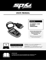
2.2 Diagnostic Trouble Codes (DTCs)
OBD II Diagnostic Trouble Codes are codes that are stored by the on-board
computer diagnostic system in response to a problem found in the vehicle. These
codes identify a particular problem area and are intended to provide you with a
guide as to where a fault might be occurring within a vehicle. OBD II Diagnostic
Trouble Codes consist of a five-digit alphanumeric code. The first character,
a letter, identifies which control system sets the code. The second character,
a number, 0-3; other three characters, a hex character, 0-9 or A-F provide
additional information on where the DTC originated and the operating conditions
that caused it to set. Here below is an example to illustrate the structure of the
digits:

3
LAUNCH CRP 429C User's Manual
EN
Figure 2-1
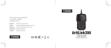
2.3 Location of the Data Link Connector (DLC)
The DLC (Data Link Connector or Diagnostic Link Connector) is typically a 16-
pin connector where diagnostic code readers interface with the vehicle’s on-
board computer. The DLC is usually located 12 inches from the center of the
instrument panel (dash), under or around the driver’s side for most vehicles. If
Data Link Connector is not located under dashboard, a label should be there
telling location. For some Asian and European vehicles, the DLC is located
behind the ashtray and the ashtray must be removed to access the connector. If
the DLC cannot be found, refer to the vehicle’s service manual for the location.

4
LAUNCH CRP 429C User's Manual
Figure 2-2
2.4 OBD II Readiness Monitors
An important part of a vehicle’s OBD II system is the Readiness Monitors, which
are indicators used to find out if all of the emissions components have been
evaluated by the OBD II system. They are running periodic tests on specific
systems and components to ensure that they are performing within allowable
limits.
Currently, there are eleven OBD II Readiness Monitors (or I/M Monitors) dened
by the U.S. Environmental Protection Agency (EPA). Not all monitors are
supported in every vehicles and the exact number of monitors in any vehicle
depends on the motor vehicle manufacturer’s emissions control strategy.
Continuous Monitors -- Some of the vehicle components or systems are
continuously tested by the vehicle’s OBD II system, while others are tested
only under specific vehicle operating conditions. The continuously monitored
components listed below are always ready:
1. Misre
2. Fuel System
3. Comprehensive Components (CCM)
Once the vehicle is running, the OBD II system is continuously checking the
above components, monitoring key engine sensors, watching for engine misre,
and monitoring fuel demands.
Non-Continuous Monitors -- Unlike the continuous monitors, many emissions
and engine system components require the vehicle to be operated under
specic conditions before the monitor is ready. These monitors are termed non-
continuous monitors and are listed below:
1) EGR System
2) O2 Sensors
3) Catalyst
4) Evaporative System
5) O2 Sensor Heater

5
LAUNCH CRP 429C User's Manual
EN
6) Secondary air Injection
7) Heated Catalyst
8) A/C system
2.5 OBD II Monitor Readiness Status
OBD II systems must indicate whether or not the vehicle’s PCM’s monitor
system has completed testing on each component. Components that have been
tested will be reported as “Ready”, or “Complete”, meaning they have been
tested by the OBD II system. The purpose of recording readiness status is to
allow inspectors to determine if the vehicle’s OBD II system has tested all the
components and/or systems.
The Powertrain Control Module (PCM) sets a monitor to “Ready” or “Complete”
after an appropriate drive cycle has been performed. The drive cycle that
enables a monitor and sets readiness codes to “Ready” varies for each
individual monitor. Once a monitor is set as “Ready” or “Complete”, it will remain
in this state. A number of factors, including erasing of Diagnostic Trouble Codes
(DTCs) with a code reader or a disconnected battery, can result in Readiness
Monitors being set to “Not Ready”. Since the three continuous monitors are
constantly evaluating, they will be reported as “Ready” all of the time. If testing
of a particular supported non-continuous monitor has not been completed, the
monitor status will be reported as “Not Complete” or “Not Ready.”
In order for the OBD monitor system to become ready, the vehicle should be
driven under a variety of normal operating conditions. These operating conditions
may include a mix of highway driving and stop and go, city type driving, and at
least one overnight-off period. For specic information on getting your vehicle’s
OBD monitor system ready, please consult your vehicle owner’s manual.
2.6 OBD II Denitions
Powertrain Control Module (PCM) -- OBD II terminology for the on-board
computer that controls engine and drive train.
Malfunction Indicator Light (MIL) -- Malfunction Indicator Light (Service Engine
Soon, Check Engine) is a term used for the light on the instrument panel. It
is to alert the driver and/or the repair technician that there is a problem with
one or more of vehicle’s systems and may cause emissions to exceed federal
standards. If the MIL illuminates with a steady light, it indicates that a problem
has been detected and the vehicle should be serviced as soon as possible.
Under certain conditions, the dashboard light will blink or ash. This indicates a
severe problem and flashing is intended to discourage vehicle operation. The
vehicle onboard diagnostic system cannot turn the MIL off until the necessary
repairs are completed or the condition no longer exists.

6
LAUNCH CRP 429C User's Manual
DTC -- Diagnostic Trouble Codes (DTC) that identifies which section of the
emission control system has malfunctioned.
Enabling Criteria -- Also termed Enabling Conditions. They are the vehicle-
specic events or conditions that must occur within the engine before the various
monitors will set, or run. Some monitors require the vehicle to follow a prescribed
“drive cycle” routine as part of the enabling criteria. Drive cycles vary among
vehicles and for each monitor in any particular vehicle. Please refer to the
vehicle’s factory service manual for specic enabling procedures.
OBD II Drive Cycle -- A specific mode of vehicle operation that provides
conditions required to set all the readiness monitors applicable to the vehicle to
the “ready” condition. The purpose of completing an OBD II drive cycle is to force
the vehicle to run its onboard diagnostics. Some form of a drive cycle needs to
be performed after DTCs have been erased from the PCM’s memory or after
the battery has been disconnected. Running through a vehicle’s complete drive
cycle will “set” the readiness monitors so that future faults can be detected. Drive
cycles vary depending on the vehicle and the monitor that needs to be reset. For
vehicle specic drive cycle, consult the service manual.
Freeze Frame Data -- When an emissions related fault occurs, the OBD II
system not only sets a code but also records a snapshot of the vehicle operating
parameters to help in identifying the problem. This set of values is referred to
as Freeze Frame Data and may include important engine parameters such as
engine RPM, vehicle speed, air ow, engine load, fuel pressure, fuel trim value,
engine coolant temperature, ignition timing advance, or closed loop status.
Fuel Trim (FT) - Feedback adjustments to the base fuel schedule. Short-term
fuel trim refers to dynamic or instantaneous adjustments. Long-term fuel trim
refers to much more gradual adjustments to the fuel calibration schedule than
short-term trim adjustments. These long-term adjustments compensate for
vehicle differences and gradual changes that occur over time.

7
LAUNCH CRP 429C User's Manual
EN
3. Product Descriptions
3.1 Outline of CRP 429C
Figure 3-1
No. Name Descriptions
1 LCD Indicates test results.
2 I/M
A quick dial to Read I/M readiness.
*Note: This funcon only applies to Diagnose.

8
LAUNCH CRP 429C User's Manual
3
Auto VIN
Detect
Press it to quickly launch the auto VIN detection
module.
*Note: To detect more and accurate VINs, a stable
network connecon is highly recommened for this
funcon.
4
Update
A quick access to the Update module.
*Note: This funcon requires a stable network
connecon.
5 Return
Exit the current program or return to the previous
screen.
6 HOME Press to the home(Job menu) screen.
7
/
Move cursor up and down for selection.
/
Move cursor left or right for selection; Or turn
page up and down when more than one page is
displayed.
8
OBD-16
connector
To connect to vehicle's DLC (Data Link Connector)
via diagnostic cable.
9 5V Charging port
To connect to external DC power for charging
CRP 429C.
10 Power
• In Off mode, press it for about 5 seconds to turn
the handset on.
• In On mode:
• Press it to activate the LCD if the LCD is off.
• Press it to turn off the LCD if the LCD lights
up.
• Press it for 3 seconds to turn it off.
11 OK Conrms a selection (or action) from a menu list.
12 Screenshots
Press it once to capture the current screen. All
screenshots are saved in the “Image” folder of
“Data”.
13
Diagnostic
Reports
A quick dial to the “Diagnostic Reports” module.
Alternatively, it can also be accessed by “Data” ->
“Diagnostic Report”.

9
LAUNCH CRP 429C User's Manual
EN
14 Help Provides detailed descriptions/tips for diagnostics.
15 Charging LED
Red means Charging and Green means Fully
charged.
3.2 Technical Specications
• Screen: 5” IPS touch screen
• RAM: 1G
• ROM: 8GB
• Battery: 4000mAh rechargeable Li-battery
• OBDII input voltage range: 9~18V
• Touch & Keypad input
• Charging via:
• DC 5V charging cable or
• Diagnostic cable through connection to vehicle’s DLC
• Dimension: 248.7mm x 93.5mm x 36mm
• Net weight: 530g
• Working temperature: -10 to 50°C (14 to 122 F°)
• Storage temperature: -20 to 70°C (-4 to 158 F°)
3.3 Accessories Checklist
For detailed accessory items, please consult from the local agency or check the
packing list supplied with CRP 429C together.
1. CRP 429C handset
2. OBD II diagnostic cable
3. DC 5V charging cable
4. User manual
5. Padded carrying case

10
LAUNCH CRP 429C User's Manual
4. Initial Use
4.1 Charging CRP 429C
There are two charging methods available:
Via Charging Cable: Plug one end of the included charging cable into the DC-IN
port of the tool, and the other end to the external DC power.
Via Diagnostic Cable: Insert one end of the diagnostic cable into the DB-15
connector of the tool, and the other end to the vehicle’s DLC.
Once the charging LED illuminates solid green, it indicates that the battery is
fully charged.
4.2 Getting Started
If it is the first time you have used this tool, you need to make some system
settings.
1. Press the [Power] button to power it on.
2. The screen displays a welcome page. Tap “Start” to go to next step.
Figure 4-1

11
LAUNCH CRP 429C User's Manual
EN
3. Choose the desired system language, and tap “Next”.
4. Choose the desired time zone, and tap “Next” to enter the WLAN setup page.
5. Slide the switch to ON, the system starts searching for all available wireless
LANs. Choose the desired WLAN access point / network,
• If the network you chose is open, you can connect directly;
• If the selected network is encrypted, you have to enter the right security
key (network password).
*Note: If you choose “Ignore” in WLAN setup, it will go into the date seng page. If the
tool has been properly connected to the Internet, the system will automacally obtain
the correct network date and me and navigate to step 6.
6. After the network connection is done, tap “Next” to congure email address.
Input the email address, and tap “Next” to navigate to the Job menu.
Figure 4-2
*Note: You are strongly recommended to fill in the valid email address. Once you
congured this opon, the system will automacally send the diagnosc report to your
email box every me a complete Auto-Detect process is successfully nished.

12
LAUNCH CRP 429C User's Manual
4.3 Job Menu
It mainly includes the following function modules.
Figure 4-3
Diagnose To congures CRP 429C to operate as a diagnostic tool.
OBD II
This option presents a quick way to check for DTCs, isolate
the cause of the illuminated Malfunction Indicator Lamp (MIL),
check monitor status prior to emissions certification testing,
verify repairs, and perform a number of other services that are
emission-related.
Reset To perform common repair & maintenance items.
Update
To update vehicle diagnostic software and APK.
*Note: This function requires a stable network connection.
Data
Includes Diagnostic report, Diagnostic record, Feedback and
Image etc.

13
LAUNCH CRP 429C User's Manual
EN
Settings
To make some system settings, including Network setup,
Email and Brightness etc.
GEAR+
(Coming soon)
An add-on module for function extension, including Promotion
message pushing and Software subscription etc.

14
LAUNCH CRP 429C User's Manual
5. Diagnose
5.1 Connection
1. Turn the ignition off.
2. Locate vehicle’s DLC socket: It provides standard 16 pins and is generally
located on driver’s side, about 12 inches away from the center of dashboard.
See Figure 2-2. If DLC is not equipped under dashboard, a label indicating
its position will be given. In case no DLC is found, please refer to Automobile
Repair Manual.
3. Plug one end of the diagnostic cable into the DB-15 connector of CRP 429C,
and tighten the captive screws. Connect the other end to the vehicle’s DLC.
Diagnostic Cable
CRP 429C
Vehicle's DLC
Figure 5-1
5.2 System Diagnosing
This function is specially designed to diagnose the 4 basic systems of ABS,
SRS, ENG and AT system.
5.2.1 Smart Diagnosis (Auto-Detect)
After connection, turn the ignition key on and the system enters auto-detect
Page is loading ...
Page is loading ...
Page is loading ...
Page is loading ...
Page is loading ...
Page is loading ...
Page is loading ...
Page is loading ...
Page is loading ...
Page is loading ...
Page is loading ...
Page is loading ...
Page is loading ...
Page is loading ...
Page is loading ...
Page is loading ...
Page is loading ...
Page is loading ...
Page is loading ...
Page is loading ...
Page is loading ...
/