Page is loading ...

UM_FB201-LX_v1.6_102720
FB201-LX
Server Barebone
User's Manual

Content
Table of Contents
Preface ������������������������������������������������������������������������������������������������ i
Safety Instructions ������������������������������������������������������������������������������ ii
About This Manual ����������������������������������������������������������������������������� iv
Chapter 1� Product Features �������������������������������������������������������������� 1
1�1 Box Contents �����������������������������������������������������������������������������������1
1�2 Specifications �����������������������������������������������������������������������������������2
1�3 Feature ���������������������������������������������������������������������������������������������3
Chapter 2� Hardware Setup ���������������������������������������������������������������� 8
2�1 Central Processing Unit Setup ���������������������������������������������������������� 8
2.1.1 Processor Installation ..........................................................................................8
2�2 System Memory �����������������������������������������������������������������������������11
2.2.1 Placement ...........................................................................................................11
2.2.2 DIMM Population ...............................................................................................12
2.2.3 Installation ..........................................................................................................15
2�3 Top Cover ���������������������������������������������������������������������������������������16
2�4 Power Supply Unit Module �������������������������������������������������������������� 17
2�5 Fan Module �������������������������������������������������������������������������������������18
2�6 Hard Disk Drive ������������������������������������������������������������������������������� 19
2�7 HDD Backplane ������������������������������������������������������������������������������� 20
2�8 Bridge Board �����������������������������������������������������������������������������������21
2�9 Riser Card ���������������������������������������������������������������������������������������22
2�10 Tool-less Slide Blade Installation �������������������������������������������������� 23
Chapter 3� Hardware Settings ���������������������������������������������������������� 27
3�1 Motherboard ���������������������������������������������������������������������������������� 27
3.1.1 Block Diagram ....................................................................................................27
3.1.2 Content List ........................................................................................................28
3.1.3 Placement ...........................................................................................................30
3.1.4 Connector ...........................................................................................................31
3.1.5 Jumper ................................................................................................................38
3�2 System LED Indicator ����������������������������������������������������������������������40
3.2.1 Front Panel LED .................................................................................................. 40
3.2.2 Internal LED ........................................................................................................41
3�3 HDD Backplane ������������������������������������������������������������������������������� 42
3.3.1 Placement ...........................................................................................................42
3.3.2 Connector and Jumper ......................................................................................43
3.3.3 LED Indicator ......................................................................................................43
Chapter 4� BIOS Configuration Settings ������������������������������������������� 44
4�1 Navigation Keys ������������������������������������������������������������������������������ 44
4�2 BIOS Menu ��������������������������������������������������������������������������������������45
4�3 Main ����������������������������������������������������������������������������������������������46
4.3.1 Main ....................................................................................................................46

4�4 Advanced����������������������������������������������������������������������������������������47
4.4.1 Peripheral Configuration .................................................................................... 47
4.4.2 Video Configuration ...........................................................................................47
4.4.3 OEMBoard Function ...........................................................................................47
4.4.4 SIO AST2500 ......................................................................................................48
4.4.5 Socket Configuration .........................................................................................48
4.4.6 ME Configuration ...............................................................................................54
4.4.7 PCH Configuration .............................................................................................55
4.4.8 H2O IPMI Configuration .....................................................................................56
4.4.9 APEI Configuration .............................................................................................56
4.4.10 Console Redirection .........................................................................................56
4.4.11 H2O Event Log Config Manager ......................................................................57
4.4.12 H2oUve Configuration .....................................................................................57
4�5 Security ������������������������������������������������������������������������������������������58
4.5.1 Security ...............................................................................................................58
4�6 Power ���������������������������������������������������������������������������������������������59
4.6.1 Power ..................................................................................................................59
4�7 Boot ������������������������������������������������������������������������������������������������60
4.7.1 Boot .....................................................................................................................60
4�8 Exit �������������������������������������������������������������������������������������������������61
4.8.1 Exit.......................................................................................................................61
Chapter 5� BMC Configuration Settings ������������������������������������������� 62
5�1 Login ����������������������������������������������������������������������������������������������62
5�2 Web GUI ���������������������������������������������������������������������������������������� 63
5.2.1 Menu Bar .............................................................................................................63
5.2.2 User Information and Quick Button ..................................................................64
5.2.3 Dashboard ..........................................................................................................65
5.2.4 Sensor ................................................................................................................. 65
5.2.5 FRU Information .................................................................................................66
5.2.6 Logs and Reports ...............................................................................................66
5.2.7 Settings ............................................................................................................... 67
5.2.8 Remote Control ..................................................................................................68
5.2.9 Power Control ..................................................................................................... 72
5.2.10 Maintenance .....................................................................................................73
5.2.11 Sign out .............................................................................................................74
Chapter 6� Technical Support ����������������������������������������������������������� 75
Content

Document Release History
Release Date Version Update Content
January
2019
1 User's Manual release to public.
Febuary
2019
1.1 Safety information update.
March
2019
1.2 Content update.
April
2019
1.3 LED Status update.
September
2019
1.4 MB settings update.
November
2019
1.5
1. Pin definition update.
2. SW update
October
2020
1.6 HW update.
Content

Copyright © 2019 AIC®, Inc� All Rights Reserved�
This document contains proprietary information about
AIC® products and is not to be disclosed or used except in
accordance with applicable agreements.

Copyright
No part of this publication may be reproduced, stored in a retrieval system, or
transmitted in any form or by any means, electronic, mechanical, photo-static, recording
or otherwise, without the prior written consent of the manufacturer.
Trademarks
All products and trade names used in this document are trademarks or registered
trademarks of their respective holders.
Changes
The material in this document is for information purposes only and is subject to change
without notice.
Warning
1. A shielded-type power cord is required in order to meet FCC emission limits and also
to prevent interference to the nearby radio and television reception. It is essential
that only the supplied power cord be used.
2. Use only shielded cables to connect I/O devices to this equipment.
3. You are cautioned that changes or modifications not expressly approved by the
party responsible for compliance could void your authority to operate the equipment.
Disclaimer
AIC® shall not be liable for technical or editorial errors or omissions contained herein.
The information provided is provided "as is" without warranty of any kind. To the extent
damages relating to the procurement of substitute products or services; or damages
for loss of data, or software restoration. The information in this document is subject to
change without notice.
Instruction Symbols
Special attention should be given to the instruction symbols below.
NOTE
This symbol indicates that there is an explanatory or
supplementary instruction.
CAUTION
This symbol denotes possible hardware impairment. Upmost
precaution must be taken to prevent serious harware damage.
WARNING
This symbol serves as a warning alert for potential body
injury. The user may suffer possible injury from disregard or
lack of attention.
Preface
i

ii
Safety Instructions
Before getting started, please read the following important cautions:
• All cautions and warnings on the equipment or in the manuals should be noted.
• Most electronic components are sensitive to electrical static discharge. Therefore, be
sure to ground yourself at all times when installing the internal components.
• Use a grounding wrist strap and place all electronic components in static-shielded
devices. Grounding wrist straps can be purchased in any electronic supply store.
• Be sure to turn off the power and then disconnect the power cords from your system
before performing any installation or servicing. A sudden surge of power could damage
sensitive electronic components.
• Do not open the system’s top cover. If opening the cover for maintenance is a must, only
a trained technician should do so. Integrated circuits on computer boards are sensitive
to static electricity. Before handling a board or integrated circuit, touch an unpainted
portion of the system unit chassis for a few seconds. This will help to discharge any
static electricity on your body.
• Place this equipment on a stable surface when install. A drop or fall could cause injury.
• Please keep this equipment away from humidity.
• Carefully mount the equipment into the rack, in such manner, that it won’t be hazardous
due to uneven mechanical loading.
• This equipment is to be installed for operation in an environment with maximum
ambient temperature below 35°C.
• The openings on the enclosure are for air convection to protect the equipment from
overheating. DO NOT COVER THE OPENINGS.
• Never pour any liquid into ventilation openings. This could cause fire or electrical shock.
• Make sure the voltage of the power source is within the specification on the label when
connecting the equipment to the power outlet. The current load and output power of
loads shall be within the specification.
• This equipment must be connected to reliable grounding before using. Pay special
attention to power supplied other than direct connections, e.g. using of power strips.
• Place the power cord out of the way of foot traffic. Do not place anything over the
power cord. The power cord must be rated for the product, voltage and current marked
on the product’s electrical ratings label. The voltage and current rating of the cord
should be greater than the voltage and current rating marked on the product.

• If the equipment is not used for a long time, disconnect the equipment from mains to
avoid being damaged by transient over-voltage.
• Never open the equipment. For safety reasons, only qualified service personnel should
open the equipment.
• If one of the following situations arise, the equipment should be checked by service
personnel:
1. The power cord or plug is damaged.
2. Liquid has penetrated the equipment.
3. The equipment has been exposed to moisture.
4. The equipment does not work well or will not work according to its user manual.
5. The equipment has been dropped and/or damaged.
6. The equipment has obvious signs of breakage.
7. Please disconnect this equipment from the AC outlet before cleaning. Do not
use liquid or detergent for cleaning. The use of a moisture sheet or cloth is
recommended for cleaning.
• Module and drive bays must not be empty! They must have a dummy cover.
• The Equipment intended for installation should be placed in Restricted Access
Location.
CAUTION
The equipment intended for installation should be placed in Restricted Access
Location.
CAUTION
There will be a risk of explosion if battery is replaced by an incorrect type. Dispose
of used batteries according to the instructions. After performing any installation or
servicing, make sure the enclosure is correct in position before turning on the power.
CAUTION
This unit may have more than one power supply. Disconnect all power sources before
maintenance to avoid electric shock.
iii

About This Manual
Thank you for selecting and purchasing the FB201-LX.
This user's manual is provided for professional technicians to perform easy hardware
setup, basic system configurations, and quick software startup. This document pellucidly
presents a brief overview of the product design, device installation, and firmware settings
for FB201-LX. For the latest version of this user's manual, please refer to the AIC®
website: https://www.aicipc.com/en/productdetail/51011.
Chapter 1 Product Features
FB201-LX is a flexible storage server barebone that is specifically designed to
accommodate diverse corporations and enterprises for managing heavy workloads and
multiple applications.
Chapter 2 Hardware Setup
This chapter displays an easy installation guide for assembling the hardware in this
product. Utmost caution for proceeding to set up the hardware is highly advised. Most of
the components are highly fragile and vulnerable to exterior influence. Do not endanger the
device by placing the device in an unstable environment.
Chapter 3 Hardware Settings
This chapter provides information for connectors, jumpers, and LED descriptions. These
descriptions assist users to configure different settings and functions of the motherboard,
as well as to confirm the location of each connector and jumper.
Chapter 4 BIOS Configuration Settings
This chapter introduces the key features of BIOS, including the descriptions and option
keys for diverse functions. These details provide users to effortlessly navigate and
configure the input/output devices.
Chapter 5 BMC Configuration Settings
This chapter illustrates the diverse functions of IPMI BMC, including the details on logging
into the web page and assorted definitions. These descriptions are helpful in configuring
various functions through Web GUI without entering the BIOS setup. For more information
of BMC configurations, please refer to IPMI BMC (Aspeed AST2500) User's Manual for a
more detailed description.
Chapter 6 Technical Support
For more information or suggestion, please contact the nearest AIC® corporation
representative in your district or visit the AIC® website: https://www.aicipc.com/en/index.
It is our greatest honor to provide the best service for our customers.
iv

Chapter 1. Product FeaturesFB201-LX User Manual
1
Spica User Manual Chapter 1. Product Features
Chapter 1� Product Features
FB201-LX is a high density storage server that includes mother board, chassis,
redundant power supplies, HDD backplane, and hotswapple fans. For more information
about our product, please visit our website at https://www.aicipc.com/en/index.
Before removing the subsystem from the shipping carton, visually inspect the physical
condition of the shipping carton. Exterior damage to the shipping carton may indicate
that the contents of the carton are damaged. If any damage is found, do not remove
the components; contact the dealer where the subsystem was purchased for further
instructions. Before continuing, first unpack the subsystem and verify that the number of
components in the shipping carton is accurate and
1�1 Box Contents
This product contains the components listed below.
Please confirm the number and the condition of the components before
installation.
• System barebone
(includes power supply, fan
& hard disk drive tray)
• Power cord (vary per region)
• 28" Slide rail x 1 set (optional)

2
Chapter 1. Product FeaturesFB201-LX User Manual
1�2 Specifications
Dimensions
(W x D x H)
mm : 438 x 800 x 88
inches : 17.2 x 31.5 x 3.5
Motherboard
AIC Server Board Lynx
Processor
Processor
Support
(Skylake and next gen. CPU)
Fabric Interface, Skylake-F SKU CPU
UPI Speeds 10.4 GT/s, 9.6 GT/s
Socket Type Socket P0 (LGA-3647 Socket)
Chipset Support
Intel® C620 PCH
System Memory
2 x DIMM per channel
DDR4 2400/2666MHz RDIMM/LRDIMM
(feature supports up to DDR4 2933MHz
by next gen. process upgrade)
- up to 384GB RDIMM SRx4
- up to 768GB RDIMM DRx4
- up to 3072GB RDIMM 3DS 8Rx4/QRx4
- up to 1536GB LRDIMM QRx4
- up to 3072GB LRDIMM 3DS 8Rx4//QRx4
next gen. Purley Refresh CPU
Front Panel
System power on/off, System ID, System reset, 1x USB 3.0 Type A
LEDs
Power status, System alert, LAN activity, Drive activity, System ID
Drive Bays
External 2.5" hot swap
24 (U.2 NVMe)
2 (15mm, rear)
Backplanes 2 x dual Broadcom/LSI PEX9765 PCIe switch backplanes
Expansion Slots
PCIe 3.0
2 x16 slots (FH)
2 x16 slots (LP) + 2 x OCP Mezzanine card
v2.0 (Optional)
Riser Card
(included)
RC-PE2U09-TY
2 x16 PCIe slots
System BIOS
BIOS Type
FLASH Interface
BIOS
Features
interface
redirection
Mode
On-board
Devices
SATA
Intel® Lewisburg PCH on-chip solution
BMC
Aspeed AST2500 Advanced PCIe Graphics &
Remote Management Processor
Serial over LAN
Network
Controllers
Intel® I210 Ethernet Controller support
dual port GbE RJ45 connectors
Mezzanine extension
for BMC dedicated management port
Graphics
Aspeed AST2500 Advanced PCIe Graphics &
Remote Management Processor
Rear I/O
LAN
management
USB
2 x USB 3.0 Type A
VGA
1 x external DB-15 VGA port
Serial Port
1 x micro USB
Power Supply
1600W 1+1 redundant power supply 80+ Platinum
AC INPUT : 200~240V,50/60Hz,12A
AC INPUT : 200-240V,50/60Hz,10A
System Cooling
4 x 60x56mm hot swap fans
System
Management
Environmental
Gross Weight
(w/ PSU & Rail)
kgs : 30.5
lbs : 67.24
Packaging
Dimensions
(W x D x H)
mm : 600 x 1060 x 320
inches : 23.4 x 41.3 x 12.5
Mounting
Standard 28" tool-less slide rail

3
Chapter 1. Product FeaturesFB201-LX User Manual
1�3 Feature
FB201-LX is a reliable 2U storage server barebone with 24 hotswap drives bays at the
front and 2 hotswap drive bays at the rear. This product is designed to accommodate the
AIC®-patented serverboard, Lynx, which supports two Intel® Xeon® Scalable Processors
and 24 DDR4 DIMM to offer greater perfomance, efficiency, and utility for our customers.
Featuring Xeon® Scalable Processor, which is emphasized for its accelerated speed and
maximized I/O expansion, this product enhances these advantages by integrating flexible
IO usage and system expansion into to provide greater bandwidth and utilization.
In addition to the noteworthy features of the barebone, FB201-LX provides immediate and
efficient management with Onboard Baseboard Management Controller and greater I/O
extension. Featuring IPMI 2.0 and Aspeed AST2500 Advanced PCIe Graphics, the server
board offers support for iKVM, Media Redirection, Smash Support, IPMI over LAN, and
Serial over LAN.
• 2U-24 Bay storage server supports 24 x U.2 NVMe drives to provide a highly dense,
all Flash storage array
• Supports two Intel® Xeon® Scalable Processors, 24 x DDR4 2666 RDIMM
• With Intel® C620 Series Chipset to provide 5+ years product life cycle
• Flexible IO usage with Max IO™ to support 4 x PCIe Gen3 x16 slot (or optional OCP
Mezzanine card)
• Onboard Baseboard Management Controller for system management and IPMI
control
• Front-to-back airflow and hot swap redundant fans to provide optimal thermal
conditions
• Customizable to meet OEM/ODM requirements

4
Chapter 1. Product FeaturesFB201-LX User Manual
Front Panel
2.5" HDD hotwap drive (U.2 NVMe)
Power On/Off Button
System HDD Activity LED
System Power LED
LAN LED
System ID LED
System Alert LED
System ID Button
System Reset Button

5
Chapter 1. Product FeaturesFB201-LX User Manual
Rear Panel
Rear Panel without 2�5" Tray
NOTE
* :RJ-11 telecom type connectors are not used for telecommunication purposes.
QSFP+ port
SFF8644 port
USB 3.0
port
Micro USB port
SFF8644 port
QSFP+ port
RJ-11 port *
VGA port
VGA port
RJ45
port
USB 3.0 Type A
low profile PCIe
RJ45
port
RJ45 dedicated to BMC
RJ45 dedicated to BMC
1600W 1+1 redundant PSU
2.5" HDD tray

6
Chapter 1. Product FeaturesFB201-LX User Manual
Top view
4 x 60 x 56mm hotswap fans4 x 60 x 56mm hotswap fans
1600W 1+1
redundant
power supply 80+
Platinum

7
Chapter 1. Product FeaturesFB201-LX User Manual
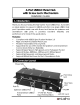
System Block Diagram
DIMM #F1
Power Connector
(1x5 pin)
CPU0_port3c
AST_USB Port #0~1 to PCH Port #4~5
DS80PCI800SQ
Box Header
FB201-LX
USB(X2)
Lewisburg-4
PCH
PCIe x16
+5VSB_MB@3A
PCIe X16 Slot
RX
P44~P47
Port1a(IOU0)
Lynx-MB
SATA#6
DIMM #L1
VGA Pin Header
PCI Express x 1
CPU1
PCH_WAKE_N
Steering
Resistors
DS80PCI800SQ
Steering
Resistors
RST_PCIE2_SLOT
PWR
(1x3 pin)
Version : A
Omni-Path
Carrier
Card
ADDRESS : 0x44 (0x88 - 0x89)
P0 CH3/DIMM1/A2
PCI-Express x 8
PEX0_1V8@2A
SFF8643
DS80PCI800SQ
2U12Bay NVMe BP
CONN A
AirMax VS2 Connector *6
CONN A
P40~P43
Port3a(IOU2)
DIMM #B1
Steering
Resistors
Pin Header
PCI-Express x 16 / TX
Port3(IOU2)
SFF8643
KRx4
CPU0_port1
SFF-8643
RJ45 x1
PCIEX48 Riser Slot
ADDRESS : 0x52 (0xA4 - 0xA5)
NGFF M.2 2242/2280
ADDRESS : 0x56 (0xAC - 0xAD)
PCIE2_SMCLK/DAT
+12V_SBB_BP@15A
CLK_100M_PCIE3_P/N
PCH_GPP_B11/BMC_GPIOG6
S25FL256SAGMFI001
Port2(IOU1)
P32~P35
LCM
P0 CH5/DIMM1/AA
ADDRESS : 0x42 (0x84 - 0x85)
Aspeed AST2500
Port3aIOU2)
PCIE2_SMCLK/DAT
CPU0
RC-PE2U09-TY
P0 CH2/DIMM1/AA
PCIe gen3
repeater
USB#3
PCIe x16
Port3c(IOU2)
DIMM #A1
ADDRESS : 0x4C (0x98 - 0x99)
PCI-Express x 16 / TX
+3VSB@1A
CN1
PCIe x16
Port2a(IOU1)
SFF-8643
PCI Express x 16
2x4P
FAN CONN
PCI Express x 16
UPI @10.4GT/s
NCSI
PCI Express x 8
P1 CH3/DIMM1/A2
Version : A
COM1
PCI-Express x 8
HFI0
PCIE1
PCI Express x 16
SPI Flash
W25Q128V
ADDRESS : 0x40 (0x80 - 0x81)
PCH_WAKE_N
2*4P
+3_3V@3A
(I2C FAN OUT)
RiserCard
(12-L)
Placement
P12~15
Code Name : MB-DPSK03
i210
I2C0_SCL/SDA
Port3c(IOU2)
PWR
XDP
PCI Express x 16
Port3a(IOU2)
DDR4 x16
PCIe gen3
repeater
Port3a(IOU2)
BRC-PE20009A
SATAPort #10
PCIe x16
SFF-8643
P1 CH0/DIMM1/A2
SATA#9
Power Connector
FAN
CPU1_port3
Power CONN /40A
From Lynx-MB
PCIe gen3
repeater
Flash
P8~11
Lynx
:
Review
UPI0
ADM213
DMI GEN3@8GT/s
P0 CH4/DIMM1/A6
DIMM #D1
CPU1
CN2
i210
SFF8643
NGFF M.2 2242/2280
SFF8643
USB#2
@6Gb/s
ADDRESS : 0x48 (0x90 - 0x11)
CPU TDP 240W
SFF8643
L1084DG
PCIe X16 Slot
RC_CPU1 BLOCK DIAGRAM
P20~23
Version : A
UPI0
LYNX MB BLOCK DIAGRAM
Hot Plug
Micro USB
RTL8201EL
COM5
Port3(IOU2)
(2x5 pin)
Lynx
P1 CH4/DIMM0/A4
CPU0_port3
UPI1
DS80PCI800SQ
USB2.0 Port #0~3
PN:
PCI Express x 8
SATAPort #11
PCIe gen3
repeater
+5V@2A
PCIe x16
GF1 x32
Bridge
Board
(16-L)
USB2.0 Port #4~5
I2C(BMC) PCIE_SMSDA/SMCLK
DIMM #A0
P24~27
DIMM #H0
PCI-E GEN3 @8GT/s X2 & SATA @6Gb/s
PCI Express x 16
SPI Flash
W25Q64BVSSIG
PCIe x16
DIMM #C0
SPI2
2*4P
Debug port
RC-PE2U09-TY
P0 CH1/DIMM1/A6
COM2
PCIe x16
2x4P (3.0mm)
12V Power input
CPU1_port2
CLK_100M_PCIE2_P/N
SFF-8643
MUX x1
CONN B
P28~31
ADM213
DMI3 x 4
(2x5 pin)
DIMM #F0
RST_PCIE0_SLOT
CPU1_VRD
VR13
Mother Board
SPI
CN1
PCI-E GEN3@8GT/s
PCI Express x 1
ADDRESS : 0x50 (0xA0 - 0xA1)
MUX
CPU1_port1
MPM3620
RX
PCI-Express x8
PCI Express x 16
CONN C
P1 CH4/DIMM1/A6
ECC DDR4 (1866/2133/2400/2667)
ADDRESS : 0x54 (0xA8 - 0xA9)
@6Gb/s
Port1(IOU0)
PCIe gen3
repeater
EDY4016AABG-DR-F-D
RX
RJ45 x1
CLK_100M_PCIE3_P/N
PL-2303HXD
CN3
DIMM #G1
DIMM #E1
ADDRESS : 0x46 (0x8C - 0x8D)
RST_PCIE2_SLOT
PEX0_0V9@30A
Mother Board
+5VSTBY_SBB
RST_PCIE1_SLOT
UPI
EEPROM
I2C4
REF_CLK
DIMM #B0
USB#0
Box Header
(COM1)
P1 CH2/DIMM0/A8
CPU0_port2
LM95241CIMM-2
SFF8643
PCI-E GEN3 @8GT/s X2 & SATA @6Gb/s
PCIe x8
TDP 19W
P0 CH2/DIMM0/A8
DS80PCI800SQ
+12V@40A
PCIe x16
PEX0_0V9A@5A
PCI-Express x 16 / RX
CPU0
P16~P19
Project Code :
PCI Express x 1
PLX
PEX9765
SPI
PWR
PCIEX48 Riser Slot
PWR
P1 CH5/DIMM0/A8
COM4
NGFF M.2 2242/2280
PCIe x16
Port2(IOU1)
PCIe X16 Slot
DIMM #L0
OCP ConnectorA (PCIe X8 gne3)
SFF-8643
DIMM #H1
SFF-8643
SFF-8643
SATA#3
ADDRESS : 0x4E (0x9C - 0x9D)
Pin Header
0R
Lynx
+12V
PCI-Express x8
DIMM #I0
SFF-8643
CPU Footprint(LGA3647-P0 NRW-F)
Secure boot key
I2C1_SCL/SDA
Skylake-EP
(Cannonlake-EP)
P1 CH5/DIMM1/AA
VGA CONN
USB(X2)
RC_CPU0 BLOCK DIAGRAM
LGA3647-0 Socket
PCIe X16 Slot
SATA#7
PCIE2
P0 CH5/DIMM0/A8
PCI-Express x8
Edge Connector
Project Name :
Project Code :
PCI Express x 16
DIMM #D0
CN2
ISL95870B
OCP ConnectorA (PCIe X8 gne3)
PCIe x8
SFF-8643
DIMM #E0
RJ45 x1
SATA#8
Port1a(IOU0)
LGA3647-0 Socket
PCIe gen3
repeater
P0 CH3/DIMM0/A0
PCH_WAKE_N
Port1a(IOU0)
PCI-Express x 16 / RX
DIMM #K0
BRC-PE20009A
LM95241CIMM
ADDRESS : 0x4A (0x94 - 0x95)
P0 CH1/DIMM0/A4
ADDRESS : 0xE2 - 0xE3
PCIE1
MPM3620
PCIe x8
PCIE3_SMCLK/DAT
AirMax VS2 Connector *7
SATA#0
Thermal
Sensor*2
PCI Express x 8
SATA#5
ECC DDR4 (1866/2133/2400/2667)
LM95241CIMM-1
RiserCard
(12-L)
PCI Express x 8
GF2 x16
@5Gb/s
RST_PCIE1_SLOT
RMII
P1 CH1/DIMM0/A4
MAX7311ATG
Port1(IOU0)
PCIe gen3
repeater
+12V
CN3
CN4
10/100Mbps dedicate
management port
P0~P3
(Internal Box Header )
Port2a(IOU1)
P0 CH0/DIMM1/A2
PCIE x2 or SATA x1
PCI Express x 2
PCIe x16
HFI0
CPU0_HP_I2C_CLK/DAT
PCIE x2 or SATA x1
PCI-Express x8
CPU TDP 240W
PN:
TPM 2.0
CKK BUF
9DB1233AGLFT
Port3a(IOU2)
SFF8643
+12V@40A
PCIe gen3
repeater
CPU0_HP_I2C_CLK/DAT
BMC Debug
USB3.0 Port #0~3
Port 48~63
P1 CH1/DIMM1/A6
UPI1
DIMM #I1
CONN B
PCH_GPP_B11/BMC_GPIOG6
LPC/eSPI
CN4
P0 CH4/DIMM0/A4
FB201-LX
Skylake-EP
(Cannonlake-EP)
Project Name :
Project Code :
Platform Environment Control Interface(PECI)
SATA#1
DS80PCI800SQ
ADM1278
RST_PCIE0_SLOT
MPQ8633
GF2 x16
P1 CH3/DIMM0/A0
+12V
Port1a(IOU0)
P36~P39
@6Gb/s
SATA#2
MUX x1
DIMM #J1
USB#1
CLK_100M_PCIE2_P/N
Port2a(IOU1)
DS80PCI800SQ
DIMM #G0
PCIE3_SMCLK/DAT
SATAPort #0~9
P1 CH2/DIMM1/AA
MAX7311ATG
CPU1_port3c
Reserved for HA system
DS80PCI800SQ
2x7P + 2x4P
Power Connector
(For HA system)
PCH_WAKE_N
JCOM4
B48-DTIET02G00A000
Platform Environment Control Interface(PECI)
2x7P + 2x4P
Power Connector
(For HA system)
PCI Express x 2
DIMM #C1
PCH
DIMM #K1
DIMM #J0
GF1 x32
NUVOTON
NPCT650
RX
P0 CH0/DIMM0/A0
PCIe x8
UPI
SFF-8643
SFF-8643
CPU0_VRD
VR13
UPI @10.4GT/s
MPQ8633
SFF8643
TPS29251
PCIE2
RC_CPU1 BLOCK DIAGRAM
SFF-8643
Project Name : Lynx
ADM213
LYNX MB BLOCK DIAGRAM
P4~P7
HFI1
P1 CH0/DIMM0/A0
HFI1
SATA#4
RC_CPU0 BLOCK DIAGRAM
Revision A01
Project Code :BBP -HD20000A_A01
Product Name : B P-HD2H13-TY
Support NVMe SSD *12
FB201-LX
DB-PEG310-TY Version :
A
BDB-PEG0000A
Project Name :
Project Code :
PN:
A
A
B
B
AN1 AN2JA6JA5JA4JA3JA2JA1
CN2011
CN2010
CN2009
CN2008
CN2007
CN2006
CN2005
CN2004
CN2003
CN2002
CN2001
CN2000
Serial Hot Plug Port ID : PORT0
Serial Hot Plug Port ID : PORT1
Serial Hot Plug Port ID : PORT2
Serial Hot Plug Port ID : PORT3
Serial Hot Plug Port ID : PORT4
Serial Hot Plug Port ID : PORT5
Serial Hot Plug Port ID : PORT6
Serial Hot Plug Port ID : PORT7
Serial Hot Plug Port ID : PORT8
Serial Hot Plug Port ID : PORT9
Serial Hot Plug Port ID : PORT10
Serial Hot Plug Port ID : PORT11
CLK_100M_PCIE2
MAX7311ATG
MAX7311ATG
MAX7311ATG
MAX7311ATG
MAX7311ATG
MAX7311ATG
MAX7311ATG
MAX7311ATG
MAX7311ATG
MAX7311ATG
U2
U3
U14
U19
U20
U21
U22
U23
U24
U25
U26
U28
U13
BP_SCL/SDA
PCIE_M1_SMCLK/SMSDA
U6
TCA9548APWR
U9
TCA9548APWR
ADDRESS : 0xE0 - 0xE1
J9J28J3 J2 J1 J7 J6 J5J8
+12V_SBB_BP@15A
+5VSTBY_SBB
J31
CLK_100M_PC
IE2 (PCIE_SMSDA/CLK)
CLK_100M_PCIE1
NCT7802Y
HW monitoring
I2C address
=0X52 (0101 001X)
0X56 (0101 011X)
MCU
MB9AF111MAPMC
PCA9554
Address:0100000xb
(For HA system)
ADM1278-1ACPZ
Hot Swap Controller
I2C Addrss: 01000010
(For HA system)
J24
J26
J25
33J22J
CPU_HP_I2C_SCL/SDA
PCIE_SMSDA/CLK
CLK_100M_PCIE1_P/N
CLK_100M_PCIE2_P/N
CPU_HP_I2C_SCL/SDA
J22
EEPROM
BP_SCL/SDA
PCIE_M1_SMCLK/SMSDA
Bridge
Board
(16-L)
JA1
J33
(I2C FAN OUT)
6J1J 7J2J 9J82J3J J5
U25
PWR
NCT7802Y
HW monitoring
I2C address
=0X52 (0101 001X)
U13
CLK_100M_PCIE1_P/N
CLK_100M_PCIE2_P/N
AirMax VS2 Connector *7
AirMax VS2 Co
nnector *6
ADM1278-1ACPZ
Hot Swap Controller
I2C Addrss: 01000010
(For HA system)
U2
MCU
MB9AF111MAPMC
U21
MAX7311ATG
PCA9554
Address:0100000xb
(For HA system)
CKK BUF
9DB1233AGLFT
CPU_HP_I2C_SCL/SDA
PCIE_SMSDA/CLK
MAX7311ATG
CLK_100M_PCIE1
CLK_100M_PCIE2
U26
MAX7311ATG
Support NVMe SSD *12
Revision A01
MAX7311ATG
Product Name : B P-HD2H13-TY
2U12Bay NVMe BP
Project Code :BBP -HD20000A_A01
ADDRESS : 0xE0 - 0xE1
Reserved for HA system
Serial Hot Plug Port ID : PORT3
Serial Hot Plug Port ID : PORT8
ADDRESS : 0x42 (0x84 - 0x85)
ADDRESS : 0x44 (0x88 - 0x89)
Serial Hot Plug Port ID : PORT4
Serial Hot Plug Port ID : PORT9
ADDRESS : 0x48 (0x90 - 0x11)
ADDRESS : 0x4E (0x9C - 0x9D)
ADDRESS : 0x54 (0xA8 - 0xA9)
ADDRESS : 0x52 (0xA4 -
0xA5)
Serial Hot Plug Port ID : PORT0
Serial Hot Plug Port ID : PORT5
Serial Hot Plug Port ID : PORT10
ADDRESS : 0x40 (0x80 - 0x81)
ADDRESS : 0x4C (0x98 - 0x99)
Serial Hot Plug Port ID : PORT1
Serial Hot Plug Port ID : PORT6
Serial Hot Plug Port ID : PORT11
AN1
ADDRESS : 0x4A (0x94 - 0x95)
ADDRESS : 0x56 (0xAC - 0xAD)
ADDRESS : 0x46 (0x8C - 0x8D)
Serial Hot Plug Port ID : PORT2
Serial Hot Plug Port ID : PORT7
ADDRESS : 0x50 (0xA0 - 0xA1)
I2C(BMC) PCIE_SMSDA/SMCLK
U9
ADDRESS : 0xE2 - 0xE3
+12V_SBB_BP@15A
CN2011
FB201-LX
DB-PEG310-TY Version : A
PN: BDB-PEG0000A
Project Name :
Project Code :
REF_CLK
J31
2x4P (3.0mm)
12V Power input
MPM3620
SFF-8643
FAN
P40~P43
PWR
TPS29251
+5V@2A
PWR
MPQ8633
PLX
PEX9765
2x4P
FAN CONN
P28~31
MPM3620
P0~P3
P16~P19
2x7P + 2x4P
Power Co
nnector
(For HA system)
Thermal
Sensor*2
P44~P47
PEX0_0V9A@5A
P24~27
+5VSB_MB@3A
+12V@40A
I2C0_SCL/SDA
P12~15
Hot Plug
I2C1_SCL/SDA
2x7P + 2x4P
Power Connector
(For HA system)
SFF-8643
+12V
Lynx-MB
0R
+12V
+12V
+3VSB@1A
P4~P7
PWR
MPQ8633
SFF-8643
+5VSTBY_SBB
Port 48~63
ADM1278
+12V_SBB_BP@15A
A03@9V0_0XEPB07859LSI
+12V@40A
+3_3V@3A
P20~23
PEX0_1V8@2A
SFF-8643
L1084DG
P36~P39
P8~11
P32~P35
Power CONN /40A
From Lynx-MB
CLK_100M_PCIE2 (PCIE_SMSDA/CLK)
J25
J26
J24
CPU_HP_I2C_SCL/SDA
+5VSTBY_SBB
0X56 (0101 011X)
J8
2NA6AJ5AJ4AJ3AJ2AJ
TCA9548APWR
U6
TCA9548APWR
CN2010
CN2009
CN2008
CN2006
CN
2004
CN2007
CN2005
CN2000
CN2003
CN2001
CN2002
MAX7311ATG
MAX7311ATG
MAX7311ATG
MAX7311ATG
MAX7311ATG
MAX7311ATG
U28
U24
U23
U22
MAX7311ATG
U20
U19
MAX7311ATG
U14
U3
Bridge Board BLOCK D
IAGRAM
Bridge Board BLOCK D
IAGRAM
NVMe BP BLOCK DIAGRAMNVMe BP BLOCK DIAGRAM
Support NVMe SSD *12
Support NVMe SSD *12

8
Chapter 2. Hardware SetupFB201-LX User Manual
2�1 Central Processing Unit Setup
The serverboard supports dual Xeon scalable processors and Socket P0 (LGA-3647).
2�1�1 Processor Installation
To ensure a safe and easy setup, you need to prepare before installation:
a T20 Torx screwdriver
ESD wrist strap/mat and conductive foam pad
Safe and stable environment
CAUTION
The pins of the processor socket are vulerable and easily susceptible to damage if
fingers or any foreign objects are pressed against them. Please keep the socket pro-
tective cover on when the processor is not installed.
CAUTION
When unpacking a processor, hold the processor only by its edges to avoid touching
the contacts.
Standard Processor Assembly:
A standard processor assembly is comprised of PHM(Processor Heatsink Module)
components and processor socket assembly.
Chapter 2� Hardware Setup
This information is provided for professional technicians only.
Heat sink
Standard
Processor Clip
Standard
Processor
Bolster Plate
Precsessor
Socket
PHM Components
Processor
Socket Assembly

9
Chapter 2. Hardware SetupFB201-LX User Manual
Processor Socket Assembly:
The server board includes two processor sockets (LGA-3647), supports one or two of
the Intel® Xeon® Processor Scalable Family and has a Thermal Design Power (TDP) of
up to 165W on selected models.
PHM (Processor Heatsink Module) Component:
This information is provided for professional technicians only.
Non Frabic
Processor
Non Frabic
Processor Clip
Heat sink

10
Chapter 2. Hardware SetupFB201-LX User Manual
PHM Screw Installation Order:
The PHM sits level with the processor socket assembly. The PHM is NOT installed
properly if it does not sit level with the processor socket assembly. Once the PHM is
seated over the processor socket assembly, the four heat sink torque screws must be
secured in the following order as shown below.
Processor Heat Sink – Top View with Screw Tightening Order
CAUTION
Failure to tighten the heatsink screws in the specified order may cause damage to the
processor socket assembly. Heat sink screws should be tighted to 12 in-lbs torque
according to the ndicated order on the top of the heatsink label.
This information is provided for professional technicians only.

11
Chapter 2. Hardware SetupFB201-LX User Manual
2�2�1 Placement
2�2 System Memory
CPU1
CPU0
CPU0
CPU1
JDIMMI0
JDIMMI1
JDIMMH0
JDIMMH1
JDIMMG0
JDIMMG1
JDIMMJ1
JDIMMJ0
JDIMMK1
JDIMMK0
JDIMML1
JDIMML0
JDIMMC0
JDIMMC1
JDIMMB0
JDIMMB1
JDIMMA0
JDIMMA1
JDIMMD1
JDIMMD0
JDIMME1
JDIMME0
JDIMMF1
JDIMMF0
/