PIPE NIPPLE
Tubo roscado
STOP / Llave de paso
THREAD SEALANT / Selladora de rosca
COPPER TUBE / Tubo de cobre
COMPRESSION NUT / Tuerca de compresión
SLEEVE / Manga
VALVE / Llave de paso
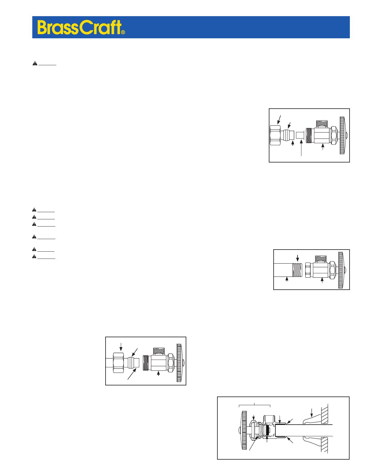
PEX TUBE
Tubo de PEX
TUBE INSERT (IF NEEDED) / Inserto para tubería
COMPRESSION NUT / Tuerca de compresión
SLEEVE / Manga
STOP / Llave de paso
ESCUTCHEN
Chapetón
FLUX
Pasta
fundente
BRASS WASHER
Rondana de latón
Cartucho
SOLDER
Soldadura
BONNET NUT
Tuerca de capuchón
SOLDER
Soldadura
STUB OUT
Caño de alimentación
RUBBER BIBB WASHER
Arandela de goma
tipo babero
PEX COMPRESSION INLET
Be sure to shut off water before starting.
For use ASTM F876/F877 PEX only.
NOTE: On 3/8 in. OD and smaller, use plastic compression sleeve. On larger than 3/8”
OD, use brass compression sleeve w/stainless steel tube insert.
1. Place compression nut and sleeve
onto the PEX tube.
2. If larger than 3/8 in. OD, insert
stainless steel tube insert.
3. A drop of general purpose oil will
make tightening easier.
4. If using a drop of oil or thread sealant
be sure the threads are clean of any
debris and that sealant is also free
of any metal debris.
DO NOT USE a putty, gasket material
or thread seal tape.
5. If using a thread sealant, apply a thin even coat to the male compression threads
only taking care not to get thread sealant on the compression ring or sealing
surface. IMPORTANT: Excessive thread sealant may cause joint to fail.
6. Hand tighten the compression nut onto the stop as far as it will allow.
7. Using hand tools, tighten 3/4 turn from the hand tight position. Note: Make sure that
the stop remains seated and square to the PEX tube. If the stop is not square to
the PEX tube, this could affect the ability to get a good connection. CAUTION: DO
NOT OVERTIGHTEN as this could lead to future failure.
8. For riser tube installation, see that section.
Tools Needed for Installation: • Wrench • Tube Cutter
FEMALE IRON PIPE (FIP INLET)
Be sure to shut off water before starting.
1. Apply thread sealant to pipe nipple.
Thread valve onto pipe. Wrench tighten.
Make sure outlet is positioned correctly.
Tools Needed for Installation:
• Thread sealant • Wrench
SWEAT INLET
Be sure to shut off water before starting.
NOTE:
MULTI TURN: Remove complete stem assembly by loosening bonnet nut and
unthreading stem ti prevent heat damage to washer. Reassembly after installation is complete
1/4-Turn Stops: Make sure the stop in in the open position. Do not turn the stop to the
off position until the stop has fully cooled. Do not use a wet rag to cool the stop.
1. Clean outside of copper stub out and inside of tting/valve with emery cloth
or steel wool and remove all loose particles.
2. Coat outside of copper stub out and inside of tting/valve with ux.
Push tting/valve over stub out and rotate to distribute ux evenly.
3. Apply heat to all sides, checking temperature occasionally by touching end
of solder to surface (not to ame). When solder liquees, temperature is correct.
Feed solder around edge of tting/valve as heat is applied.
4. While stub out is still hot, carefully wipe valve with damp rag to leave an
attractive chrome-like nish. Avoid moving tting/valve until solder hardens.
Tools Needed for Installation:
• Emery cloth or steel wool • Flux • Solder • Wrench • Damp rag
CAUTION: FOR USE WITH WATER IN ACCESSIBLE LOCATIONS ONLY.
CAUTION: DO NOT SWEAT WITHIN 12 INCHES OF A G2
™
1/4 TURN STOP.
CAUTION: DO NOT USE G2 OR MULTI-TURN STOPS ON RECIRCULATION
SYSTEMS EXCEDDING 115˚ F.
CAUTION: DO NOT USE WITH CONNECTORS HAVING A
SOLID BRASS CONE
OR BULL NOSE DESIGN - FRACTURES CAN DEVELOP.
CAUTION:
STOP MUST BE USED IN THE FULLY OPENED OR FULLY CLOSED POSITION.
CAUTION: OUTLET MUST BE CAPPED IF STOP IS BEING USED AS A
TERMINATION POINT.
Do not reuse, inspect annually, replace if damaged, deterioration or corrosion is
detected. Failure to do so may result in product failure and property damage.
Manufacturer assumes no responsibility for failure due to improper installation.
GENERAL INSTRUCTIONS:
• BrassCraft Water Supply Stops are avilable in a variety of congurations. Select the
inlet and outlet instructions that apply to the product purchased.
• Be sure stub out and riser are square, round and free of burrs.
• CAUTION: Overtightening can cause product to crack and fail over time. See more
detailed instructions below:
COPPER COMPRESSION INLET
Be sure to shut off water before starting.
For use with type L or M copper only.
1. Place compression nut and sleeve
onto the copper tube.
2. A drop of general purpose oil will
make tightening easier.
3. If using a drop of oil or thread
sealant be sure the threads are clean
of any debris and that sealant is also
free of any metal debris. DO NOT USE a putty, gasket material or thread seal tape.
4. If using a thread sealant, apply a thin even coat to the male compression threads
only taking care not to get thread sealant on the compression ring or sealing
surface. IMPORTANT: Excessive thread sealant may cause joint to fail.
5. Hand tighten the compression nut onto the stop as far as it will allow.
6. Using hand tools, tighten 3/4 turn from the hand tight position. Note: Make sure
that the stop remains seated and square to the copper tube. If the stop is not
square to the copper tube, this could affect the ability to get a good connection.
CAUTION: DO NOT OVERTIGHTEN as this could lead to future failure.
7. For riser tube installation, see that section.
Tools Needed for Installation: • Wrench • Tube Cutter
Water Supply Stops
CAUTION: DO NOT INSTALL THIS PRODUCT UNTIL YOU READ AND UNDERSTAND
ALL INSTRUCTIONS. FAILURE TO FOLLOW THESE INSTRUCTIONS MAY RESULT IN
PERSONAL INJURY, PROPERTY DAMAGE OR PRODUCT FAILURE.
For over 70 years, BrassCraft
®
water supply stops have set the
bar for quality, reliability and proven performance. Machined from
solid brass, BrassCraft water stops are available in a variety of
styles congurations that offer signicant advantages for you and
your customer. BrassCraft water stops are designed, machined and
assembled in the USA.
Kt
®
Series ¼ Turn Ball Stops are rst in its class with a robust design
and superior performance. The KT Series precision machined brass ball
is specially engineered and mated with PTFE seats to provide smooth
operation even after long periods of non-use. 100% leak tested
G2
®
Series ¼ Turn Stops offer durable construction and innovation.
One-piece shut off mechanism provides smooth operation even
after long periods of non-use. Available with a full range of options,
including BrassCraft’s push connect technology Multi-turn stops are
the industry standard with proven performance. Its one-piece brass
body provides strength, durability and long-lasting performance.
INSTALLATION INSTRUCTIONS
INSTALLATION INSTRUCTIONS (CONTINUED)


