Dometic 9300-9400 Series Installation guide
- Category
- Sanitary ware
- Type
- Installation guide

1
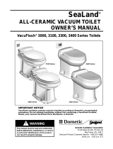
9300-9400 Series
RushFlush
™
Toilets
INSTALLATION
Pressure-assisted toilet
Installation manual
EN
Mazerier-WC
Bedienungsanleitung............. 13
DE
WC dilacérateur
Mode d’emploi ................. 22
FR
Inodoro triturador
Manual de instrucciones . . . . . . . . . . 32
ES
Toilet met versnijdingspomp
Instructihandleiding.............. 42
NL
WC di macerazione
Manuale di istruzioni ............. 51
IT
Silppuripumppu-wc
Ohjekirja...................... 60
FI
Macerator-toalett
Bruksanvisning ................. 69
SV
Findelingstoilet
Instruktionsvejledning ............ 78
DA
Macerator-toalett
Brukerhåndbok................. 87
NO
9300 series
9400 series

2
Dometic 9300-9400 Series RushFlush Toilets
E
A
B
C
D
F
G
4
3
1
4
5
6
7
12
3
2
9300 series 9400 series
A
F
D
E
G
H I K M
N O
P
L
J
B,C
1
2
8 9
10
11

3
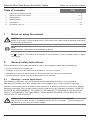
1 Notes on using the manual .................................................3
2 General safety instructions ..............................................3 - 4
3 Components ............................................................5
4 Specications ........................................................5 - 6
5 Installation ..........................................................7 - 11
6 Customer service........................................................12
EN
Table of contents
Dometic 9300-9400 Series RushFlush Toilets Notes on using the manual
1 Notes on using the manual
Caution!
Safety Instruction: Failure to observe this instruction can cause material damage and impair
the function of the device.
Note
Supplementary information for operating the device.
g.
1
2, page 2 : This refers to an element in an illustration. In this example, item 2 in gure
1 on page 2.
2 General safety instructions
The manufacturer will not be held liable for claims for damage resulting from the following:
• Faulty installation or connection
• Damage to the unit from mechanical inuences, misuse or abuse
• Alterations to the unit without express written permission from the manufacturer
• Use for purposes other than those described in this manual
2.1 Warnings – marine applications
The following statements must be read and understood before installing, servicing and/or
operating this product on a boat. Modication of this product may result in property damage.
Dometic recommends that a qualied marine technician or electrician install or service this product.
Equipment damage, injury to personnel or death could result from improper installation. DOMETIC
ACCEPTS NO RESPONSIBILITY OR LIABILITY FOR DAMAGE TO EQUIPMENT, OR INJURY OR
DEATH TO PERSONNEL THAT MAY RESULT FROM IMPROPER INSTALLATION, SERVICE OR
OPERATION OF THIS PRODUCT.
Caution! NOT INTENDED FOR RAW WATER FLUSH TOILET SYSTEMS
The RushFlush toilet system is not designed to ush with seawater. To assure optimum
performance, use only fresh water supply.

4
General safety instructions Dometic 9300-9400 Series RushFlush Toilets
Caution! Hazard of Flooding
If the toilet is connected to ANY through-the-hull ttings, properly installed seacocks MUST
be installed in all piping connected to through-the-hull ttings. Seacocks MUST be easily
accessible to all users of the toilet or secondary valves tted in hoses where they are easily
accessible. All valves MUST be full bore valves and of marine quality. Screw-to-close gate
valves are not recommended. Failure to do so can result in ooding which can cause loss
of property and life.
Caution! Hazard of Flooding
If toilet is connected to ANY through-the-hull ttings, ALL exible hoses must be of marine
sanitation quality and must be secured to ANY ttings (such as those at seacock, vented
loop or toilet) with two stainless steel, worm-drive hose band clamps at each connection.
Connections MUST be checked frequently for integrity. Failure to comply can result in
ooding which can cause loss of property and life
.
Caution! Hazard of Flooding
If toilet rim is below the waterline at ANY time (during any conditions of heel, load or trim)
and is connected to ANY through-the-hull ttings, properly positioned ventilated (vented)
loops MUST be installed in discharge piping to prevent potential back siphonage of sea-
water into the boat. Failure to do so can result in ooding which can cause loss of property
and life.
Caution! Hazard of Flooding
If toilet uses raw water for ushing at ANY time, a raw water pump controlled by an auto-
matically operating demand switch MUST NOT be installed. If the onboard water valve or
any plumbing connections were to leak, the automatically operated pump would start and
could ood the boat. Failure to comply can cause loss of property and life.
Caution! Hazard of Flooding
Before beginning any work on this product, be sure that all electrical power to the unit has
been turned off and that seacocks are in the CLOSED or OFF position. Failure to do so can
result in ooding which can cause loss of property and life.
Caution! Hazard of Shock or Fire
Always use recommended fuse, circuit breaker and wire size. Failure to do so can result in
re that can cause the loss of property and life.
Caution!
Overlling the holding tank can create serious damage to the sanitation system, such as
rupturing the holding tank and releasing tank contents into the bilge. To prevent this pos-
sibility, Dometic recommends using the “full” tank shut-down relay in the toilet’s electronic
control module. The “full” signal from the holding tank can be generated by an optional
Dometic DTM01C tank monitor or DTM04 four-level tank monitor system.

5
Dometic 9300-9400 Series RushFlush Toilets Components
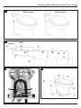
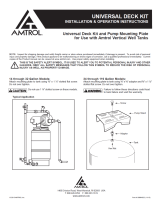
3 Components
Basic system diagram* (fig.
2
, page 2) Toilet diagram ( (g.
3
, page 2)
Ref. Description
A RushFlush toilet
B “Full tank” status panel (9300 only)
C Flush switch and status panel
(9400 only)
D Rim water supply line
E Lower bowl water supply line
F Check valve
G Blackwater holding tank
H High-ow electric water valve
I Maintenance valve
J Potable water pressure tank
K Check valve
L Fresh water to other xtures
M Pressure gauge
N High-ow water pump
O Pump inlet strainer
P Freshwater holding tank
* Recommended system conguration. Not all
components may be used in your RushFlush toilet
system.
Ref. Description
1 Flush handle (9300 series)
2 Flush handle switch
3 Anti-siphon valve
4 Vacuum breaker
5 Water ow control module
6 Upper rim water supply line
7 Lower bowl water supply inlet
(attached to supply line, not included)
8 Water valve, upper rim
9 Discharge loop
10 Discharge outlet
11 Sealing grommet
12 Discharge oor ange
Refer to complete parts list (packed separately) for
additional information.
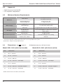
4 Specifications
4.1 Materials
Toilet: vitreous ceramic
Control module housing: ABS
Discharge outlet: high-tech polymer
Discharge floor flange: ABS
Flush switch panel frame: ABS
Flush switch panel: polycarbonate resin
Flush handle: plated brass (on applicable toilet
models)

6
4.2 Approvals
• EMC Directive 2004/108/EC
• CE compliant components
4.3 Minimum System Requirements
Electrical
Power draw
1.2 amps @ 12 V DC
0.6 amps @ 24 V DC
Circuit breaker/fuse
recommended size
2 amps @ 12 V DC
1 amp @ 24 V DC
Water Supply
Upper rim 0.5 in. NPT inlet, water valve
Lower bowl jet 1 in. NPT inlet, water valve
Flow rate 15 gpm/57 lpm @ 30-50 PSI / 207-345 kPa
Discharge
Inside diameter 1.5 in./38 mm pipe or 1.875 in./47 mm hose
Horizontal run gravity drain *
Required components
Water pump ** 15 gpm/57 lpm
Potable water pressure tank ** 150 PSI working pressure rating
Electric ush switch Dometic
* Horizontal discharge plumbing must drop a minimum of 0.125 in./3 mm for every 1 ft./30.5 cm of horizontal run.
** Purchased separately. Water pump may be part of vessel’s potable water system.
Specications subject to change without notice.
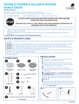
4.4 Dimensions (g.
4
, page 2) All dimensions may vary ±3/8 inch (10 mm)
Model 9431, 9441 (with flush switch)Model 9331, 9341 (with flush handle)
Ref. Dimension
A 19 in. / 483 mm
B 14 in. / 356 mm
C 21.5 in. / 546 mm
D 17.5 in. / 445 mm - seat height
E 17 in. / 432 mm
F 10.5 in. / 267 mm - centerline rough-in
G 33.5 in. / 851 mm - seat lid up
Ref. Dimension
A 19 in. / 483 mm
B 16.5 in. / 419 mm*
C 21.5 in. / 546 mm
D 17.5 in. / 445 mm - seat height
E 17 in. / 432 mm
F 10.5 in. / 267 mm - centerline rough-in
G 33.5 in. / 851 mm - seat lid up
* width measurement includes flush handle
Specifications Dometic 9300-9400 Series RushFlush Toilets

7
Dometic 9300-9400 Series RushFlush Toilets Installation
5 Installation
5.1 General guidelines
For optimum toilet system preformance, follow these guidelines. Make sure to also follow any
governing codes or standards that apply to your installation.
Fresh Water Supply System Plumbing (g.
2
, page 2) DO NOT USE RAW WATER SUPPLY
1. All water supply system plumbing should be 1 in. ID, with working pressure ratings above the
maximum water pump pressure. (100 PSI minimum recommended).
2. Water inlet strainer: 1 in. ID, 40 mesh
3. Pressure gauge: 0-100 PSI
4. Water pump: Grundfos
®
MQ3-35 or equivalent is recommended.
• 1 in. NPT connections
• Internal pressure switch: 50 PSI cut-out, 30 PSI cut-in
• Pump current draw is 8 amps @ 110V, 4 amps @ 220V, other pump manufacturers may vary.
• 15 GPM needed; pump actually rated at 22 GPM max. ow with no restrictions
• Depending on pump installation parameters, a pump of adequate suction lift capability
should be considered. The MQ3 pump has 25 feet of suction lift capability, but it varies
depending on horizontal suction run.
5. Potable water pressure (accumulator) tank: AMTROL
®
Well-X-Trol
®
WX-105-PS or equivalent
is recommended.
• 3/4 in. NPT, or larger, connection
• 5 gallon total volume, 1.8 gallon drawdown @ 30/50 PSI
• Air pressure charge should be set to 2-4 PSI below pump cut-in pressure.
• One 5-gal. accumulator tank recommended for up to 6 heads.
6. Pressure relief valve:
• Installation recommended by accumulator tank manufacturer
• Should be installed near accumulator tank and pump, and set to open at excessive water
system pressures. This protects fresh water system in case of pressure switch malfunction.
7. Check valve: will isolate the toilet system from the rest of the onboard freshwater system;
spring check, 1 in.
8. Rim wash valve inside toilet:
• 1/2 in. NPT connection
• This water supply line can intersect from main 1 in. distribution line prior to high-ow water
jet valve using 1/2 in. plumbing to toilet.
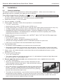
9. Electric high-flow water jet valve and maintenance ball valve, supplied with every toilet:
• 1 in. NPT connections
• Water jet valve should be closest to toilet. Maintenance ball
valve should be farthest from toilet – refer to direction arrow on
top of water jet valve inlet port.
• An in-line strainer is installed into the water jet valve inlet at the
factory. The cone shape protrudes out and against the direc-
tion of water ow away from the center of the valve, pointing
towards the maintenance ball valve.
• The water jet valve features a small white manual override lever
located next to the solenoid. This must be vertical for correct electrical operation. However,
it can be turned to the horizontal position to manually test the water system. Be sure to
return it back to vertical when testing is nished.
Electric water
jet valve

8
Installation Dometic 9300-9400 Series RushFlush Toilets
Discharge Plumbing
1. 1/8 in. per foot minimum downhill slope in discharge line is required, keeping all lines as short
and straight as possible.
2. 1-1/2 in. ID pipe or 1-7/8 in. ID hose may be used
• If using 1-1/2 in. pipe:
- Use DWV (drain, waste & vent) pipe ttings that incorporate sweeping changes of direction.
- Do not use schedule 40 or 80 ttings that have tight turns. They will hinder ow of
wastewater to holding tank.
- Install unions as deemed necessary for service.
• If using 1-7/8 in. hose:
- Eliminate hose sags and low spots that may hinder ow of wastewater to holding tank.
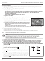
3. Check valve (apper style) supplied with every toilet:
• Install this valve as close to toilet as possible, on the discharge
side of the toilet plumbing before the waste line joins with any
common discharge line.
• The valve must be installed with the apper oriented correctly.
- When open, the apper “hinge” must be at the highest pos-
sible location.
- Flapper must open in line with the direction of ow.
- Use caution when gluing valve into place. Make sure excess glue does not contact apper.
4. For ushing overboard through seacock:
• Loop inside toilet must be above waterline.
• Seacock must be 1-1/2 in. full-ow, located no lower than 12 in. below water line.
5.2 Toilet with through-the-floor connections
Note
If replacing an existing center-discharge toilet, make sure the center of the existing
discharge ange is at least 10-1/2 in. (267 mm) from the back wall, then proceed to
Step 5 for proper positioning of water line and electrical wiring access holes.
1. Carefully unpack toilet bowl and oor ange adapter.
2. Position ceramic bowl in the space intended. Conrm that adequate clearance is available for
opening the seat and lid, and, for model 9310, using the ush handle on the left side of toilet.
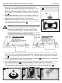
3. Mark the oor at the rear corners of the toilet bowl. Measure the distance between the two
marks and divide in half to nd the toilet centerline. Mark the oor at the rear wall for the primary
centerline (
5
).
4. Draw a primary centerline on the oor at least 14 in. (356 mm)
long. Mark the center of the oor ange access hole at
10-1/2 in. (267 mm) from the wall (
6
).
5. For the upper rim water supply line and electrical wires access
hole, mark another center spot 6 in. (152 mm) from the back
wall (
7
).
6. At the wall, mark a secondary centerline 3.25 in. (83 mm) to
the left of the primary centerline, and draw the secondary line
about 4 in. (102 mm) long from the wall. Mark the center for
the lower bowl water supply line access hole 2 in. (51 mm)
from the wall (
8
).
5
6
7
8
2 in.
6 in.
3.25 in.
Check valve
Actual model may vary from image being shown.

9
7. Make a 4-1/4 in. (108 mm) diameter hole at the primary
centerline intersection furthest from the wall. Make a 1-1/2 in.
(38 mm) diameter hole at the mark closer to the wall for the
upper rim water line and electrical wires, and at the mark on
the secondary centerline for the lower bowl water supply line
(g.
9
).
8. (9400 series toilet only) Plan ush switch panel location on a
wall so that electrical connections can be made with cables
provided. Be sure panel and wires cannot get wet.
9. (9400 series toilet only) Use Dometic wall switch template to
mark location of fastener and access holes. Drill 1 in. dia. hole,
then fasten panel bracket to wall (g.
10
).
Caution
Preferrably, the discharge oor ange should be installed
directly on the nished oor. However, if the bottom
of oor ange and bottom of ceramic toilet must be
mounted at different heights, the oor ange must be
mounted within 3/8 in. (10 mm) of the bottom of the toilet
(see illustrations below) or leakage may result.
Below-Floor Installation
Above-Floor Installation
10. Insert discharge oor ange into largest hole, orient slots front-to-back, and secure to the oor
with #14 x 1-1/2 in. screws and washers provided. If desired, allow screws to be slightly loose
for front-to-back bowl positioning adjustment. 1/2 in. of front-to-back adjustment is available
(g.
11
).
11. Install sealing grommet into top of discharge oor ange (g.
11
) and lubricate inside diameter
of sealing grommet hole with dishwashing soap.
12. While keeping toilet level, carefully lower toilet to the oor so that toilet discharge outlet inserts
into sealing grommet (g.
12
). Make sure bottom of ceramic toilet sets at on oor.
13. Slide toilet front-to-back until desired bowl location is achieved (near to or against back wall).
Make toilet bowl straight with back wall and mark holes for two mounting bolts (g.
13
).
Dometic 9300-9400 Series RushFlush Toilets Installation
10
9
11
12
13

10
Installation Dometic 9300-9400 Series RushFlush Toilets
14. Carefully raise toilet up from oor ange and set aside. Tight-
en oor ange screws (if loose for adjustment). Drill 3/16 in.
pilot holes in the oor for the ceramic toilet mounting bolts.
15. Route 1/2 in. ID upper rim water line through the hole on the
primary centerline. Provide 1/2 in. NPT connection for upper
rim water line (g.
14
).
16. Route 1 in. ID lower bowl water line through the hole on the
secondary centerline, leaving about 3 feet of extra hose to
create a exible loop (g.
14
).
17. WITH ELECTRICAL POWER OFF, route #18 gauge stranded
copper wire from DC power source (positive and ground)
through a fuse or circuit breaker. Leave at least 18 in.
(457 mm) of wire for connecting to toilet (g.
14
). Also route
any other optional wiring according to wiring diagram.
18. (9400 series toilet only) Connect Dometic ush switch cable
to toilet control module (RJ45 connector) and route cable to
access hole at ush switch location. Attach cable to ush
switch, then snap the panel cover onto the bracket (g.
15
).
19. Connect discharge plumbing from holding tank to discharge
oor ange, using system discharge plumbing recommenda-
tions from Section 5.1.
20. With toilet positioned near oor ange, connect upper rim
exible water line to water valve, DC power wires, and lower
bowl water line to toilet (looping water line as shown)
(g.
16
). Also complete any other wiring connections to
control module. Refer to enclosed wiring diagrams.
21. (9400 series toilet only) To attach RJ45 connector from ush
switch, remove control module from back of toilet (locking
fabric strips will come apart), route cable up through toilet
plumbing lines to connect to module (g.
17
), then
re-attach control module to back of toilet.
22. Set the toilet back in place by inserting discharge outlet into
the sealing grommet and aligning fastener holes in oor with
holes on sides of ceramic toilet base.
Caution
DO NOT ATTEMPT TO SLIDE THE TOILET OVER THE FLANGE
ADAPTER. THE TOILET MUST BE SET DOWN OVER THE
ADAPTER TO PREVENT POSSIBLE DAMAGE.
23. Route 1 in. ID water line so that it loops inside back of toilet
(g.
3
, page 2).
24. Turn on electrical power and water to toilet. Lift ush handle,
or push “add water” button, for several seconds. Then ush
the toilet a few times and observe operation. Adjust upper
rim valve and lower jet valve times as needed to lengthen or
shorten ush duration.
25. Wait one hour, then inspect the oor around and under the
rear of the toilet for leaks or dampness. If no leaks are
present, secure to the oor with #14 x 2-1/2 in. long lag bolts.
Install decorative caps by pushing them onto bolt heads
(g.
18
). Toilet is ready for use.
END
14
16
17
18
15

11
Dometic 9300-9400 Series RushFlush Toilets Installation
19
5.3 Toilet with through-the-wall connections
1. To install wiring and plumbing connections through the wall,
determine the primary centerline location as described in
Section 5.2, steps 2 and 3.
2. Mark horizontal primary centerline for plumbing and wiring
access holes on wall according to g.
19
. Mark secondary
centerline for lower bowl water line 3 in. (76 mm) to left of
primary centerline. Mark hole locations as indicated.
3. Drill two 1-1/2 in. (38 mm) dia. holes for water supply lines
and wiring, and drill 2.25 in. (57 mm) dia. hole for discharge
plumbing (g.
19
).
4. Follow toilet installation instructions beginning at Section 5.2,
step 15. For lower bowl water line, install an elbow tting (not
provided) so that 1 in. ID exible water line can loop upward
and back down to inlet at toilet base (g.
3
7, p. 2).
5. Before securing toilet to oor with lag bolts (step 25), be sure
to drill 3/16 in. pilot holes.
5.4 9300 series toilet system status panel
(optional accessory)
1. Plan status panel location so that electrical connections can
be made between toilet and status panel with wiring cable
provided. Be sure cable and connections cannot get wet.
2. Use Dometic wall switch template to mark location of
fastener and access holes for status panel. Drill 1 in. (25 mm)
wiring access hole, then fasten panel bracket to wall
(g.
20
).
3. Attach cable (provided with status panel) to status panel’s
RJ45 connector, then route other end of cable through wall
access hole to oor access hole at toilet base.
4. Snap the status panel cover onto the panel bracket (g.
20
).
5. WITH ELECTRICAL POWER OFF, connect cable from the
status panel to the toilet control module (g.
21
). To attach
RJ45 connector, remove control module from back of toilet
(locking fabric strips will come apart), route cable up through
toilet plumbing lines to connect to module, then re-attach
control module to back of toilet.
6. After all toilet wiring connections are made, turn on
electrical power to toilet system. A steady green “Power On”
light indicates that electrical power to the toilet is activated.
20
21
3 in.
4 in.
1.5 in.
1.5 in. dia.
2.25 in. dia.
1.5 in. dia.
Lower bowl
water line
Upper rim water line,
electrical wires
Discharge
outlet

12
Customer service Dometic 9300-9400 Series RushFlush Toilets
There is a strong, worldwide network to assist
in servicing and maintaining your sanitation
system. For the Authorized Service Center near
you, please call from 8:00 a.m. to 5:00 p.m. (ET)
Monday through Friday.
You may also contact or have your local
dealer contact the Parts Distributor nearest
you for quick response to your replacement
parts needs. They carry a complete inventory
for the Dometic product line.
Telephone: 1-800-321-9886 U.S.A. and Canada
330-439-5550 International
Fax: 330-496-3097 U.S.A. and Canada
330-439-5567 International
Web site: http://www.Dometic.com
http://www.DometicSanitation.com
6 Customer service
Dometic is a customer-driven, world-leading provider of leisure
products for the RV, automotive, truck and marine markets. We supply
the industry and aftermarket with a complete range of air conditioners,
refrigerators, awnings, cookers, sanitation systems, lighting, mobile
power equipment, comfort and safety solutions, windows, doors and
other equipment that make life more comfortable away from home.
Dometic supplies a wide range of workshop equipment for service
and maintenance of built-in air conditioners. Dometic also provides
specially designed refrigerators for hotel rooms, ofces, wine storage
and transport and storage of medical products.
Our products are sold in almost 100 countries and are produced mainly
in wholly-owned production facilities around the world.
Grundfos
®
is a registered trademark of Grundfos Management A/S
AMTROL
®
and Well-X-Trol
®
are registered trademarks of AMTROL, Inc.
Dometic Corporation, Sanitation Division
13128 State Rt. 226, P.O. Box 38
Big Prairie, OH 44611 USA
1-800-321-9886 • Fax: 330-496-3097
www.Dometic.com
REVISION A
Form No. 600346748 9/17
©2017 Dometic Corporation
-
 1
1
-
 2
2
-
 3
3
-
 4
4
-
 5
5
-
 6
6
-
 7
7
-
 8
8
-
 9
9
-
 10
10
-
 11
11
-
 12
12


Dometic 9300-9400 Series Installation guide
- Category
- Sanitary ware
- Type
- Installation guide
Ask a question and I''ll find the answer in the document
Finding information in a document is now easier with AI
Related papers
-
Dometic Electronic Water Valve Replacement Owner's manual
-
-
-
-
-
-
-
-
-
Other documents
-
 Sun-Mar 510 PLUS, W Installation guide
-
 SeaLand 3000 User manual
-
 Water Worker UNVDKT Operating instructions
-
none DF1080 Installation guide
-
West Marine 14974265 Owner's manual
-
JABSCO Twist n Lock User manual
-
 Croydex WL610722H User manual
-
-
 Whitehaus Collection WHMFL3222-EB Installation guide
-


