
YAMAHA ELECTRONICS CORPORATION, USA 6660 ORANGETHORPE AVE., BUENA PARK, CALIF. 90620, U.S.A.
YAMAHA CANADA MUSIC LTD. 135 MILNER AVE., SCARBOROUGH, ONTARIO M1S 3R1, CANADA
YAMAHA ELECTRONIK EUROPA G.m.b.H. SIEMENSSTR. 22-34, 25462 RELLINGEN BEI HAMBURG, GERMANY
YAMAHA ELECTRONIQUE FRANCE S.A. RUE AMBROISE CROIZAT BP70 CROISSY-BEAUBOURG 77312 MARNE-LA-VALLEE CEDEX02, FRANCE
YAMAHA ELECTRONICS (UK) LTD. YAMAHA HOUSE, 200 RICKMANSWORTH ROAD WATFORD, HERTS WD18 7GQ, ENGLAND
YAMAHA SCANDINAVIA A.B. J A WETTERGRENS GATA 1, BOX 30053, 400 43 VÄSTRA FRÖLUNDA, SWEDEN
YAMAHA MUSIC AUSTRALIA PTY, LTD. 17-33 MARKET ST., SOUTH MELBOURNE, 3205 VIC., AUSTRALIA
Printed in Japan
QR64642
©2005 All rights reserved.
PDM-4220
G
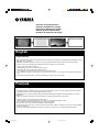
PDM-4220
High definition plasma monitor
Moniteur plasma haute définition
USER’S MANUAL
MANUEL UTILISATEUR
BEDIENUNGSANLEITUNG
BRUKSANVISNING
MANUAL DEL USUARIO
11/2/05, 9:06 PM1

1
ENGLISH
Thank you very much for purchasing the Yamaha High Definition
Plasma Monitor.
Before using your monitor, please carefully read this manual so you
will know how to operate the monitor properly. Keep this manual in a
safe place. You will find it useful in the future.
Notes on lnstallation Work:
This product is marketed assuming that it is installed by qualifed
personnel with enough skill and competence. Always have an
installation specialist or your dealer install and set up the product.
YAMAHA cannot assume liabilities for damage caused by mistake
in installation or mounting, misuse, modification or a natural
disaster.
Note for Dealers:
After installation, be sure to deliver this manual to the customer
and explain to the customer how to handle the product.
Notes about This Manual
• The information in this manual is subject to change without
notice.
• While meticulous care has been taken in the preparation of this
manual, you are requested to notify your dealer or us should
you have any comments, views or questions about our product.
• Fully understand the prerequisites to using the product, such
as hardware and software specifications and constraints, in
using the product. We are not held liable for damages caused
by improper handling of the product.
• Reproduction of this manual in whole or in part without our prior
written permission is prohibited.
• The product names mentioned in this manual may be
trademarks or registered trademarks of their respective
owners.
USER’S MANUAL

2
FEATURES
Large-screen, high-definition plasma
display panel
The 42-inch colour plasma display panel, with a resolution of
1024 (H) x 1024 (V) pixels, creates a high-definition, large-screen
(aspect ratio : 16:9) and low-profile flat display. Free from
electromagnetic interferences from geomagnetic sources and
ambient power lines, the panel produces high-quality display
images free from colour misconvergence and display distortion.
High Performance Digital Processor
A wide range of input signals can be handled, including
composite, component, and HDMI.
High Defination Digital Processor creates the fine-textured image
with dynamic contrast.
In addition, it corresponds to a broad array of personal computer
signals, from 640 x 400, and 640 x 480 VGA to 1600 x 1200 UXGA.
(Analog input)
Easy-to-use remote control and on screen
display system
The remote control included eases the work of setting display
controls. Further, the on-screen display system, displays the status
of signal reception and display control settings in an easy-to-view
fashion.
The “HD ready” Logo is a trademark of EICTA.
Connecting to an Audio Visual Divice
• Three Scart terminals
*1
,composite/S terminal
*2
,a component
terminal
*3
,and a HDMI terminal have been added.A composite
video output terminal is also provided as a monitering output.
*1
AV1 scart applies to composite/ S-video
*2
AV2 and AV3 apply to composite/ RGB
*3
A composite/S terminal = Side Input
With AV4 input,if a composite terminal and a component terminal
are used at the same time, the component terminal would govern.
• A wide range of devices can be also connected besides personal
computers.
Options
Ask your local retail dealer for further details on the following
optional attachments.
• Pedestal (PDS-342)
• Wall mounting unit (PWK-242)
• Wood bezel (4 colours)
• This User’s Manual was printed before final product
development. After printing, some product specifications may
change due to operational upgrades and other reasons. In this
case, the specifications of the product itself will take precedence
over the specifications in this manual.
• TRADEMARK ACKNOWLEDGEMENT
VGA and XGA are registered trademarks of International
Business Machines Corporation.
APPLE and Macintosh are registered trademarks of Apple
Computer, Inc.
All brand or product names are trademarks or registered
trademarks of their respective holders.
FEATURES ................................................... 2
SUPPLIED ACCESSORIES ............................ 2
CAUTION: READ THIS BEFORE
OPERATING YOUR UNIT. ........... 3
PRECAUTIONS ............................................. 7
COMPONENT NAMES .................................. 8
Main Unit ............................................................................. 8
Remote control .................................................................... 9
Loading Batteries ............................................................. 9
Handling the Remote Control ........................................... 9
INSTALLATION INSTRUCTIONS ................ 12
Installation ......................................................................... 12
Anti-tumble measures ....................................................... 12
Connecting to an Audio Visual Device ............................. 13
Connecting to a PC ........................................................... 15
Mounting the Side Input .................................................... 16
Power Cord Connection .................................................... 17
OPERATING INSTRUCTIONS ..................... 18
Turning Power On and Off ................................................ 18
Input Switching ................................................................. 19
Size Switching ................................................................... 19
Volume Adjustment ........................................................... 21
Audio Mute ........................................................................ 21
Input Signal Screen Display ............................................. 22
Displaying MULTI PICTURE .............................................. 23
Picture Freezing ................................................................ 25
Using the Menu Screen (on-screen display system) ........ 26
SETUP MENU (TV mode) .................................................. 27
SETUP MENU (Video mode) ............................................. 29
SETUP MENU (RGB mode: RGB1 (DVI-PC),
RGB2 (RGB)) ................................................................. 30
FUNCTION MENU ............................................................ 32
PICTURE MENU (TV/Video mode) .................................... 33
PICTURE MENU (RGB mode) .......................................... 36
AUDIO MENU ................................................................... 37
TIMER MENU .................................................................... 38
LANGUAGE MENU ........................................................... 38
OTHER FUNCTIONS ................................... 39
Automatic Store ................................................................ 39
Audio Switching ................................................................ 40
Power Save Mode ............................................................. 41
DVD Player Selection ........................................................ 41
Signal Check (RGB mode) ............................................... 42
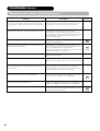
TROUBLESHOOTING ................................. 43
Symptoms That Seemingly Appear to be Failures ........... 43
Actions to Correct Abnormal Displays .............................. 45
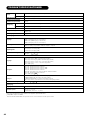
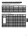
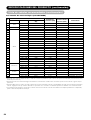
PRODUCT SPECIFICATIONS ...................... 46
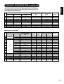
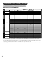
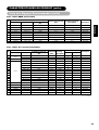
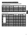
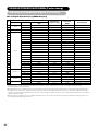
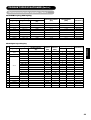
Signal Input ....................................................................... 47
Recommended Signal List ................................................ 48
CONTENTS
• Remote control (RPD-342)
• Batteries (2) (AA,R06,UM-3)
• Power cord
• Side input
SUPPLIED ACCESSORIES

3
ENGLISH
CAUTION: READ THIS BEFORE OPERATING YOUR UNIT.
This Plasma monitor has been designed and manufactured to meet international safety standards, but like any electrical equipment, care must
be taken if you are to obtain the best results and safety is to be assured.
Before using this product, please read and understand the Safety Instructions thoroughly to ensure correct usage, and follow all the
instructions.
Never use the monitor if a problem occurs.
Abnormal operations such as smoke, strange odor, no image, no sound, excessive sound, damaged casing, elements, cables, penetration of
liquids or foreign matter, etc. can cause a fire or electrical shock.
In such case, immediately turn off the power switch and then disconnect the power plug from the power outlet. After making sure that the
smoke or odor has stopped, contact your dealer. Never attempt to make repairs yourself because this could be dangerous.
Do not insert liquids or foreign objects.
Penetration of liquids or foreign objects could result in fire or electrical shock. Use special caution in households where children are present.
If liquids or foreign objects should enter the projector, immediately turn off the power switch, disconnect the power plug from the power outlet
and contact your dealer.
• Do not place the monitor in a bathroom.
• Do not expose the monitor to rain or moisture.
• Do not place flower vases, pots, cups, cosmetics, liquids such as water, etc on or around the monitor.
• Do not place metals, combustibles, etc. on or around the monitor.
Never disassemble or modify the monitor.
The monitor contains high voltage components. Modification could result in fire or electrical shock.
• Never remove any fixed cover.
Do not give the monitor any shock or impact.
If the monitor should be shocked and/or broken, it could result in an injury, and continued use could result in fire or electrical shock.
If the glass panel is broken or damaged, immediately turn off the power switch, disconnect the power plug from the power outlet and contact
your dealer.
Do not place the monitor on an unstable surface.
If the monitor should be dropped and/or broken, it could result in an injury, and continued use could result in fire or electrical shock.
• Do not place the monitor on an unstable, slanted or vibranting surface such as a wobbly or inclined stand.
Do not obstruct the ventilation of the monitor.
If the ventilation is obstructed during the operation of the monitor or just after switching off the power, it could result in damage and shorten the
lifespan of your monitor due to overheating. Make sure there is ample ventilation.
• Keep a space of 100mm (10cm) or more between the sides, rear and top of the monitor and other objects such as walls.
• Do not place anything around ventilation openings of the monitor.
• Never block ventilation openings.
• Do not put the plasma display panel side up.
• Do not cover the monitor with a tablecloth, etc.
• Do not place the monitor on a carpet or bedding, or near a curtain.
Use only the correct power outlet.
Incorrect power supply could result in fire or electrical shock. Use only the correct power outlet depending on the indication on the monitor and
the safety standard.
• The enclosed power cord must be used depending on the power outlet to be used.
Be cautious of the power cord connection.
Incorrect connection of the power cord could result in fire or electrical shock.
• Do not touch the power cord with a wet hand.
• Check that the connecting portion of the power cord is clean (with no dust), before using. Use a soft and dry cloth to clean the power plug.
• Insert the power plug into a power outlet firmly. Avoid using a loose, unsound outlet or contact failure.
• Do not cut off the fitted power plug, the removal of which could lead to impaired performance. If you wish to extend the lead, obtain an
appropriate extension lead or consult your dealer.
• Should you require replacing the fuse in the molded plug with a new fuse, then please replace with new one of the same value, type and
approval as the original. Ensure the fuse cover is returned to its original position.
Be sure to keep safety ground connection.
Connect the ground terminal of AC inlet of this monitor with the ground terminal provided at the power outlet using the enclosed power cord. If
the provided plug does not fit your outlet, consult an electrician for replacement of the obsolete outlet.

4
CAUTION: READ THIS BEFORE OPERATING YOUR UNIT. (continued)
Be careful in handling the power cord and external connection cables.
If you keep using a damaged power cord or cables, it can cause a fire or electrical shock. Do not apply too much heat, pressure or tension to
the power cord and cables.
If the power cord or cables are damaged (exposed or broken core wires, etc.), contact your dealer.
• Do not place the monitor or heavy objects on the power cord and cables. Also, do not place a spread, cover, etc, over them because this
could result in the inadvertent placing of heavy objects on the concealed power cord or cables.
• Do not pull the power cord and cables. When connecting and disconnecting the power cord or cables, do it with your hand holding the plug
or connector.
• Do not place the cord near the heater.
• Do not touch the power plug just after disconnecting it from the power outlet to prevent electric shock.
• Do not touch the power plug when lightening is close to you.
• Avoid coiling the power cord and bending it sharply.
• Protect the power cord from being walked on, pinched particularly at plugs, conveniences receptacles, and the point where they exit from
the apparatus.
• Do not modify the power cord.
Be careful in handling the battery of the remote control.
Incorrect handling of the battery could result in fire or personal injury. The battery may explode if not handled properly.
• Keep the battery away from children and pets. If swallowed consult a physician immediately for emergency treatment.
• Do not allow the battery to be exposed to fire or water.
• Avoid fire or high-temperature environment.
• Do not hold the battery with metallic tweezers.
• Keep the battery in a dark, cool and dry place.
• Do not short circuit the battery.
• Do not recharge, disassemble or solder the battery.
• Do not physically impact the battery.
• Use only the battery specified in the manual of this monitor.
• Make sure the plus and minus terminals are correctly aligned when loading the battery.
• If you observe a leakage of the battery, wipe out the liquid and then replace the battery. If the liquid adheres your body or clothes, rinse well
with water.
• Obey the local laws on disposing the battery.
FOR THE CUSTOMERS IN THE U.K.
THIS PRODUCT IS SUPPLIED WITH A TWO PIN MAINS PLUG FOR USE IN MAINLAND EUROPE. FOR THE U.K. PLEASE REFER TO THE
NOTES ON THIS PAGE.
IMPORTANT FOR UNITED KINGDOM
WORDING FOR CLASS I EQUIPMENT INSTRUCTION BOOKS AND LABELS
The mains lead on this equipment is supplied with a molded plug incorporating a fuse, the value of which is indicated on the pin face of the
plug. Should the fuse need to be replaced, an ASTA or BSI approved BS 1362 fuse must be used of the same rating. If the fuse cover is
detachable never use the plug with the cover omitted. If a replacement fuse cover is required, ensure it is of the same colour as that visible on
the pin face of the plug. Fuse covers are available from your dealer.
DO NOT cut off the mains plug from this equipment. If the plug fitted is not suitable for the power points in your home or the cable is too short
to reach a power point, then obtain an appropriate safety approved extension lead or consult your dealer.
Should it be necessary to change the mains plugs, this must be carried out by a competent person, preferably a qualified electrician.
If there is no alternative to cutting off the mains plug, ensure that you dispose of it immediately, having first removed the fuse, to avoid a
possible shock hazard by inadvertent connection to the mains supply.
WARNING: THIS EQUIPMENT MUST BE EARTHED IMPORTANT
The wires in the mains lead are coloured in accordance with the following code :
Green and Yellow = Earth, Blue = Neutral, Brown = Live.
As these colours may not correspond with the coloured markings identifying the terminals in your plug, proceed as follows:
The wire which is coloured Green and Yellow must be connected to the terminal in the plug which is marked with the letter E or by the earth
symbol
or coloured Green or Green and Yellow.
The wire coloured Blue must be connected to the terminal marked with the letter N or coloured Blue or Black. The wire coloured Brown must
be connected to the terminal marked with the letter L or coloured Brown or Red.
Blue and Neutral
Brown to Live
Fuse
Cord Clamp
Green and Yellow
to Earth

5
ENGLISH
CAUTION: READ THIS BEFORE OPERATING YOUR UNIT. (continued)
Be careful in moving the monitor.
Neglect could result in an injury or damage.
• Do not move the monitor during use. Before moving, disconnect the power plug and all external connections.
• You are advised to move the monitor with two persons.
• Avoid any impact or shock to the monitor; particularly take care of glass screen.
Do not put anything on top of the monitor.
Placing anything on the monitor could result in loss of balance or falling, and cause an injury or damage. Use special caution in households
where children are present.
Avoid a humid or dusty place.
Placing the monitor in a smoke, a highly humid, dusty place, oily soot or corrosive gas could result in fire or electrical shock.
• Do not place near the kitchen, a humidifier or other place where there is oil, smoke or humidity.
Avoid a high temperature environment.
The heat could have adverse influence on the monitor and other parts, and could result in transformation, melting or fire.
• Do not place the monitor, the remote control and other parts in direct sunlight or near a hot object such as heater, etc.
• Do not put the monitor in a place where the temperature is widely changing.
Remove the power cord for complete separation.
• For safety purposes, disconnect the power cord if the monitor is not to be used for prolonged periods of time.
• Before cleaning, turn off and unplug the monitor. Neglect could result in fire or electrical shock.
How to view the monitor
If you use the monitor in too dark a room, your eyes may become tired.
Please use it in a reasonably bright room.
Avoid direct rays of the sun to the screen in order to prevent eye fatigue.
Your eyes will get fatigued after viewing the monitor for long period of time.
Relax your eyes by viewing away from the monitor from time to time.
Please watch the monitor in downward direction.
Installation environment
Do not obstruct a ventilation hole.
Do not put the monitor on carpet or blanket, or near a curtain which has a possibility of obstructing a ventilation hole of the monitor.
Do not put the monitor in the following places.
• Hot places such as near heater, place exposed to the direct rays of the sun.
• A place where the temperature is widely changing.
• Places with soot, dust or high humidity.
• Poor air ventilation place.
• Place near fire.
• A wet place such as bathroom,or shower room.
• Place where you can trip over it.
• Always vibrating or stongly vibrating places.
• Distorted or unstable places.

6
CAUTION: READ THIS BEFORE OPERATING YOUR UNIT. (continued)
Note on image retention
The plasma monitor illuminates phosphor to display images. The phosphor has a finite illumination life. After extended periods of illumination,
the brightness of the phosphor will be degraded to such extent that stationary images would burn-in that part of the screen as grayed-out
images.
Tips to prevent such image retention are:
• Do not display images having sharp brightness differences or high-contrast images, such as monochrome characters and graphic
patterns, for long.
• Do not leave stationary images appearing for long, but try to refresh them at appropriate intervals of time, or try to move them using screen
saver function.
• Turn down the contrast and brightness controls.
How to clean the plasma display panel of the monitor
Before cleaning the monitor, turn off the monitor and disconnect the power plug from the power outlet.
To prevent scratching or damaging the plasma display panel face, do not knock or rub the surface with sharp or hard objects. Clean the
screen with a soft cloth moistened with warm water and dry with a soft cloth. If it is not enough, then use a cloth with mild detergent. Do not
use harsh or abrasive cleaners.
How to clean the cabinet of the monitor
Use a soft cloth to clean the cabinet and control panel of the monitor. When the plasma monitor is excessively soiled dilute a neutral
detergent in water, wet and wring out the soft cloth and afterward wipe with a dry soft cloth.
Never use acid/alkaline detergent, alcoholic detergent, abrasive cleaner, powder soap, OA cleaner, car wax, glass cleaner, etc. especially
because they would cause discoloration, scratches or cracks.
Prevention of an obstacle to Radio receivers
This monitor has been designed pursuant to the international EMI standards. This is to prevent a problem to Radio receivers.
• Keep the monitor away from Radio.
• Adjust Radio antennas in order for the monitor not to receive interference.
• The antenna cable of Radio should be kept away from the monitor.
• Use a coaxial cable for antenna.
You can check if this monitor influences Radio receivers by turning off all other equipment other than the monitor.
If you find a problem receiving Radio when using the monitor, check the instructions mentioned above.
Precautions for the cable connection
• Do ensure that all connections, (including the power plug, extension leads and interconnections between the pieces of equipment), are
properly made and in accordance with the manufacturers instructions. Switch off and withdraw the power plug before making or changing
connections.
• Confirm the connector is fixed tightly when the signal cable is connected.
Also confirm the screws on the connector are tightened.
• Plug the power cord of the monitor into a different socket from that for other equipment, such as Radio etc.
• Use a plug with ground terminal and make sure that it connects to the ground.
Precaution during transportation
Please pay attention when you transport this monitor because it is heavy.
Furthermore, use the original carton box and its packaging materials when the monitor is transported.
Failure to transport the monitor in any carton except the original carton may result in damage to the monitor.
Save the original carton box and all packing material.
Do not physically impact the remote control.
A physical impact could cause damage or malfunction of the remote control.
• Take care not to drop the remote control.
• Do not place heavy objects on the remote control.
Avoid strong rays.
Any strong rays (such as direct sun rays or room lighting) onto the remote control sensors could invalidate the remote control.
Avoid radio interference.
Any interfering radiation could cause distorted images or noises.
• Avoid radio generator such as a mobile telephone, transceiver, etc. around the monitor.
Set the sound volume at a suitable level.
It is better to keep the volume level low and close the windows at night to protect the neighborhood environment.

7
ENGLISH
CAUTION: READ THIS BEFORE OPERATING YOUR UNIT. (continued)
Precautions for the installation
• Do not use makeshift pedestals and NEVER fix legs with wood screws - to ensure complete safety, always fit the manufacturers approved
pedestal or legs with the fixings provided according to the instructions.
• Use only with the cart, pedestal, tripod, bracket, or table specified by the manufacturer, or sold with the apparatus. When a cart is used,
use caution when moving the cart/apparatus combination to avoid injury from tip-over.
• This product is designed to comply with the recommended safety standards for tilt and stability. Do not apply excessive pulling force to the
front, or top, of the cabinet that could cause the product to overturn resulting in product damage and/or personal injury.
• Follow instructions for wall, shelf or ceiling mounting as recommended by the manufacturer.
• Only use the attachments/accessories specified by the manufacturer.
• Consult your dealer if you are in any doubt about installation, operation or safety of your equipment.
Other precautions
• Do not leave equipment switched on when it is unattended unless it is specifically stated that it is designed for unattended operation or has
a stand-by mode. Switch off using the switch on the equipment and show your family how to do this. Make special arrangements for infirm
or handicapped people.
• Disposal of this product may require specific instructions pertaining to your resident region.
• Never guess or take any chances with electrical equipment of any kind - it is better to be safe than sorry!
PRECAUTIONS
• Please read this User's Manual thoroughly, especially the "CAUTION: READ THIS BEFORE OPERATING YOUR UNIT." and the
"PRECAUTIONS" sections. Mis-use may cause damage to your plasma monitor, which could shorten its lifespan, or cause injury to yourself.
Should you encounter any difficulty in the set-up or operation of your monitor, firstly refer to the Troubleshooting guide at the rear of this
manual.
In the unlikely event of a problem occurring with your plasma monitor, switch off at the mains sockets, pull out the plugs, and contact your
dealer immediately.
• Under no circumstances remove the rear cover of your plasma monitor.
Never guess or take any chances with electrical equipment of any kind - it is better to be safe than sorry!
• It is prohibited for the end user of this product to copy, reverse engineer or reverse compile the software included therein, save to the extent
permitted by law.
• After the plasma monitor has been turned on for any length of time, you will notice that the screen becomes warm. Please note that this is
normal.
Sometimes the screen might have some tiny bright or dark spots. Please note that this is normal.
•To prevent scratches or damages to the plasma display panel, do not knock or rub the surface with sharp or hard objects.

8
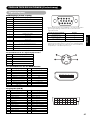
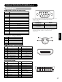
COMPONENT NAMES
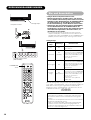
Main Unit
Cabinet
(front frame)
Panel
Front
Control panel
• Adjustment buttons are located
on the bottom.
• The back cover is provided with
indications to distinguish the
adjustment buttons.
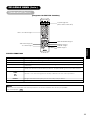
26
• ( ) indicates the function whilst the MENU is displayed on the screen.
•The main power switch is located at the
back, on the lower surface.
Remote-control
receiver
Indicating lamp
Main power switch
18
18
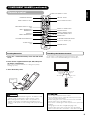
9
Menu button
INPUT SELECT button
(OK button)
19
CHANNEL
UP/DOWN buttons
(SELECT button)
18
SUB-POWER button
VOLUME
UP/DOWN
buttons
( ADJUST
buttons)
21
19
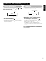
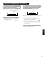
Caution when moving the main unit
• As this product is heavy, whenever it is moved, two
people are required to transport it safely.
• Whenever the unit is moved it should be lifted forwards
using the two handgrips at the back, and the unit should
then be held at the base on both sides for stability.
Rear
External device connection terminals
15
Handgrips
Handgrips Handgrips
RGB input terminals
Pedestal (option)

9
ENGLISH
STANDBY/ON
RECALL
TV
DVD
/I
i
+
AV 1 AV 2 AV 3 AV 4
AV 5
MENU
VOL PRO G
A. MODE P. MODE
RETURN
AV 6 RGB 1 RGB 2
23
456
78
0
9
?
i
I/II
2-4-12
1
OK
+
P+
P
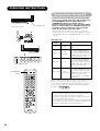
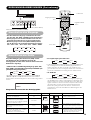
Loading Batteries
1.Press the h mark on the battery cover and slide off the
cover.
2.Insert the two supplied batteries (AA, R06, UM-3) into
the battery compartment.
Make sure you insert the batteries according to the polarity
markings (+ and –).
3. Close the battery cover.
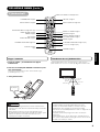
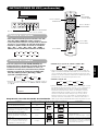
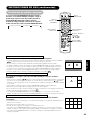
Handling the Remote Control
Use the remote control within 5m from the front of the unit’s
remote-control sensor and within 30 degrees on both sides.
• Do not use new and old batteries together. The batteries could
explode or leak, resulting in fires, physical injury, or stains.
• When loading batteries, observe their correct polarities as
marked on the product. If loaded in the wrong direction, the
batteries could explode or leak, resulting in fires, physical injury,
or stains.
ATTENTION
• Do not drop or impact the remote control.
• Do not splash the remote control with water or put it on a wet
object to avoid possible failures.
• Before leaving the remote control out of use for an extended
period of time, remove the batteries from it.
• If the remote control begins to lack responsiveness, replace the
batteries.
• Strong light such as direct sunlight impinging on the
photoreceptor of the remote control can cause operational
failure. Position this unit to avoid direct contact with such light.
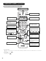
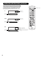
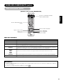
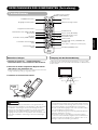
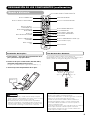
COMPONENT NAMES (continued)
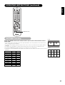
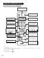
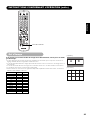
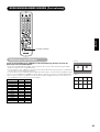
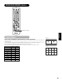
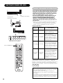
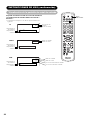
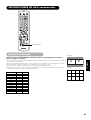
Remote control
STANDBY/ON button
INPUT SELECT buttons
MENU button
OK button
AUDIO MODE button
VOLUME UP/DOWN button
PROGRAM SELECT buttons
(TV)
TV/TEXT button
(TV)
MULTI MODE button
RECALL button
FUNCTION SELECT switch
PICTURE MODE button
CH I/CH II button (TV)
CHANNEL UP/DOWN button
MUTE button
STANDBY/ON
RECALL
TV
DVD
/I
i
+
AV 1 AV 2 AV 3 AV 4
AV 5
MENU
VOL PROG
A. MODE P. MODE
RETURN
AV 6 RGB 1 RGB 2
23
456
78
0
9
?
i
I/II
2-4-12
1
OK
+
P
+
P
Within 30
degrees
Within 30
degrees
About 3m
About 3m
About 5m
CAUTION
DVD CONTROL button
RETURN button
SELECT/ADJUST button
MULTI PICTURE button
Press h
FREEZE button

10
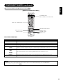
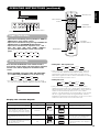
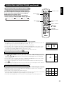
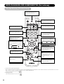
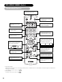
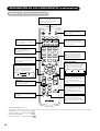
COMPONENT NAMES (continued)
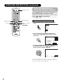
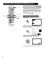
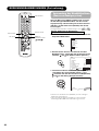
Remote control (continued)
Dynamic
Natural
Cinema
Movie Music
Favourite Speech
PICTURE MODE
You may recall the picture mode by
pressing this button. Each time pressed,
picture mode is changed in following
sequence.
INPUT SELECT
Press this button to change input
mode. *2
DVD CONTROL
You can use these buttons to operate
the selected brand of DVD player.
PROGRAM SELECT
Press these buttons to select a TV
program directly.
AUDIO MODE
You may recall the audio mode by
pressing this button. Each time pressed,
audio mode is changed in following
sequence.
FUNCTION SELECT
TV or DVD
MULTI MODE
In multi-picture mode, pressing this
button will change the multi-picture
mode.
CH I/II
This button is for A2 / NICAM
models only.
MULTI PICTURE
Press this button to change the
screen to multi-pictures. Press it
again to return to normal picture.
MUTE
Press this button to turn off the set
sound. When press again or the
volume up button, the audio will be
restored.
FREEZE
Press this button to change the
picture to freeze mode. Press it again
to return to normal picture.
ZOOM
Press this button can change Picture size.
RECALL (TV/Video/RGB)
Press this button to display input signal.
*1
TIME(TV)
Pressing this button can indicate the
time by On-Screen display when
receiving a TV program on the screen
including TELETEXT service with the
time information.
STANDBY/ON
RECALL
TV
DVD
/I
i
+
AV 1 AV 2 AV 3 AV 4
AV 5
MENU
VOL PROG
A. MODE P. MODE
RETURN
AV 6 RGB 1 RGB 2
23
456
78
0
9
?
i
I/II
2-4-12
1
OK
+
P+
P
*1 FUNCTION SELECT
This remote control has functions to control other makers of DVD Player and DVD Recorder. Use the TV/DVD switch to select either TV or
DVD mode.
For more details, refer to 41 .
*2 INPUT SELECT
For details, refer to
19

11
ENGLISH
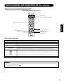
COMPONENT NAMES (continued)
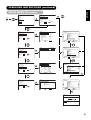
Remote control (continued)
STANDBY/ON
RECALL
TV
DVD
/I
i
+
AV 1 AV 2 AV 3 AV 4
AV 5
MENU
VOL PROG
A. MODE P. MODE
RETURN
AV 6 RGB 1 RGB 2
23
456
78
0
9
?
i
I/II
2-4-12
1
OK
+
P+
P
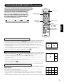
TEXT / TV + TEXT button
SUB TITLE button
TV/TEXT button
PAGE UP/DOWN button
COLOUR buttons
(RED, GREEN, YELLOW, BLUE)
REVEAL button
INDEX button
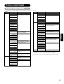
NOTE
• Certain pages do not show linked pages at the bottom of the screen. To display linked pages, press the INDEX button.
• Refer to Teletext Language shown on .
Function
This switches the receiver between the TV mode and the TELETEXT mode.
In TELETEXT mode, this button switches between TV+TEXT screen (split) and TELETEXT only.
This selects the Index page.
Use this to access a subtitle service directly rather than through a TELETEXT service (subject to subtitle
service broadcasting).
This allows the screen to return to the TV mode temporarily whilst searching for a required text page.
When the required text page has been received, the page number wiill be displayed at the top left of the
screen. Press the CANCEL button again to display the TELETEXT screen.
Each of these buttons selects a link page displayed at the lower part of the screen.
This allows hidden information (found on some teletext pages) to be displayed on the screen.
This button increases / decreases the TELETEXT page number.
28
TELETEXT FUNCTION
Buttons on Remote Control
TV / TEXT
TEXT / TV + TEXT
INDEX
SUB TITLE
CANCEL
RED
GREEN
YELLOW
BLUE
REVEAL
PAGE UP / DOWN
[Button for TELETEXT Mode]
CANCEL button

12
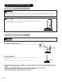
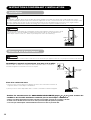
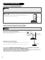
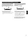
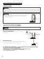
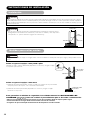
Anti-tumble measures
Have this unit mounted in a stable place. Take measures to prevent it from tumbling down to avoid possible physical injury.
Securing to a wall or pillar
Use a commercially available cord, chain and clamp, secure the set to a firm wall or pillar.
Securing desktop
1) Using wood screws (two), fasten the set to the clamping screw holes on the rear of the
stand as shown.
2) Using commercially available wood screws, secure the set firmly in position.
INSTALLATION INSTRUCTIONS
Installation
• In order to prevent an internal temperature increase, maintain a space of 10cm (4 inches :
For a desktop set-up) or more between the sides and other objects such as walls, etc.,
so that the ventilation holes are not blocked.(*)
10cm (4 inches) or more
*
Cord
or
chain
Clamp
Hook
Chain
cord or chain
clamp
Wall or Pillar
Two places
Wood screw
Use one of the special mount units to install this product. A mount of insufficient strength or inadequate design can cause overturning or
dropping and result in fire, electrical shock or injury. Please note that our company assumes absolutely no responsibility for personal
injuries or property damage caused by use of other mount units or improper installation.
WARNING
CAUTION
CAUTION
Read CAUTION ( to ) carefully to ensure maximum safety before proceeding to these
steps:
• Choose an appropriate site and install the product on a level table where the stand is secure.
• Install the monitor to have ready access to a power socket available.
• Make sure that the power switch of this device is turned off.
7
3

13
ENGLISH
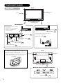
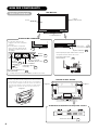
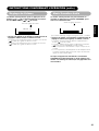
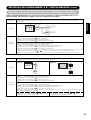
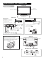
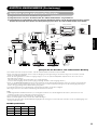
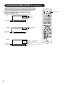
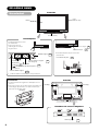
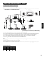
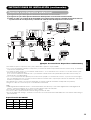
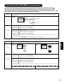
(1) Make sure that the power switch of the monitor is turned off.
(2) Make sure that the power switch of the audio visual device is turned off.
(3) Use a commercially available cable and connector to connect the signal input terminal on the rear panel of this
device and the signal output terminal of the audio visual device.
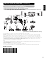
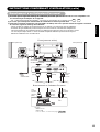
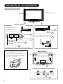
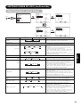
INSTALLATION INSTRUCTIONS (continued)
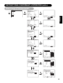
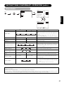
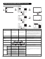
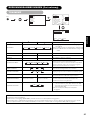
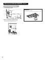
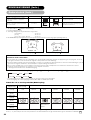
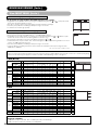
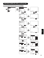
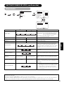
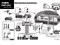
Connecting to an Audio Visual Device
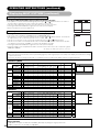
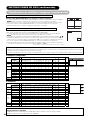
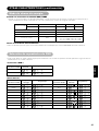
• AV1 SCART applies to composite/S-video, and AV2 and AV3 SCART apply to composite/RGB.
• If a component input terminal and a composite input terminal of AV4 connect to the monitor at the same time, component input would
govern.
• If video equipment with an S video output terminal is used, cabling by the S video cable is recommended to provide finer video quality.
(If an S video input terminal and a video input terminal of AV5 (side input) connect to the monitor at the same time, S video input would
govern.)
• If the OUTPUT (Monitor) terminal is connected to an external monitor with a 75 Ohm terminal, it is possible to view the same image as on the
main unit. But it is possible to monitor only the composite video signal from AV1 ~ AV5 input that is displayed on the screen at the time.
• Set-Top Box is only for an AV1 input. (Tuner output signal is available only for AV1.)
• Secure connecting cables to the stand with the provided clamp.
HDMI
• HDMI (High-Definition Multimedia Interface) is a digital interface based on DVI (Digital Visual Interface), which is an added function for
audio-video equipment.
• It does not have degradation by transmission since it is digital.
• With only one cable, it is possible to transmit both picture signals and audio signals.
• In case of using analog audio, when connecting with DVI-HDMI transformation connector, use analog audio terminal for AV4 input.
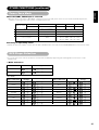
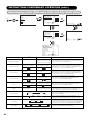
[An example of connecting audio visual devices]
AV1
AV2
AV3
CVBS
‡
‡
‡
SCART Specification
Monitor (rear panel)
Speaker (R)
Speaker (L)
Power
cord
Antenna
S-video
‡
—
—
RGB
—
‡
‡

14
INSTALLATION INSTRUCTIONS (continued)
Connecting to an Audio Visual Device (continued)
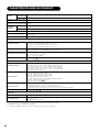
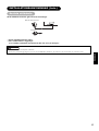
Precautions when connecting the antenna
• Please use a coaxial cable which is free from interference to connect the antenna. Avoid using a parallel flat feeder wire as interference
may occur, causing reception to be unstable and stripe noise to appear on the screen.
• Avoid using indoor antenna as this may be affected by interference. Please use CATV net or outdoor antenna.
• Keep the power cord as far away from the antenna wire as possible.
If there are noise appearance in the picture of VHF-Low band channel, please use the double-shielded cable (not provided) for RF LEADS to
reduce the noise.

15
ENGLISH
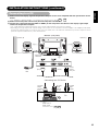
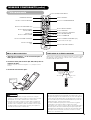
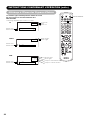
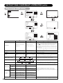
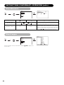
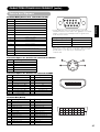
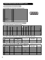
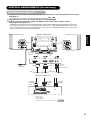
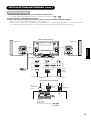
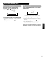
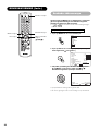
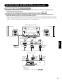
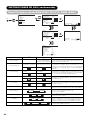
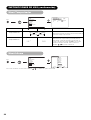
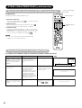
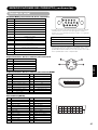
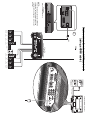
(1) Make sure that the display signal of the personal computer to be used is compatible with the specifications of this
device.
• See “PRODUCT SPECIFICATIONS” concerning the specifications of this device ~ .
(2) Make sure that the power switch of the personal computer is turned off.
(3) Connect the signal input terminal (RGB 1 or RGB 2) on the rear panel of this device to the display signal output
terminal of the personal computer.
• Use a cable that fits the input terminal of this device and the output terminal of the personal computer.
• Depending on the type of personal computer being connected, the use of an optional conversion adapter or the adapter provided with
the personal computer may be necessary in some cases. For details, refer to the instruction manual of the personal computer or ask the
personal computer manufacturer or your local retail dealer.
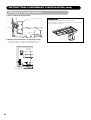
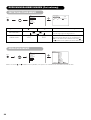
INSTALLATION INSTRUCTIONS (continued)
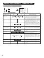
Connecting to a PC
46
50
(D-sub)(DVI)
Monitor (rear panel)
Speaker (R) Speaker (L)
Power cable
connector
Power
cord
To signal
output
terminal
(DVI)
To audio
output
terminal
3.5mm
Stereo
mini jack
PC
To signal
output
terminal
(D-sub)
Connecting to a PC Device
• Setting
RGB1: DVI-PC
RGB2: RGB
For details, refer to
49 50

16
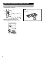
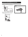
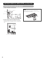
INSTALLATION INSTRUCTIONS (continued)
Mounting the Side Input
1. Attach the holder for the side input.
NOTE
About the fixing screw for the Side Input
• The screw for fixation is attached on the holder with the tape
as shown below.
2. Mount the side input into the securing holder.
Fasten the side input with the speaker holder by the screw.
See the below figure how to treat the cable.
Screw x 2
Holder
Screw hole
Screw
Clamp
Side input

17
ENGLISH
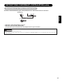
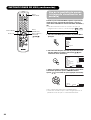
Connect the power cord, after completing all other connections.
1 Connect the power cord to this device.
2 Connect the power cord plug to the power outlet.
(The type of plug is different from this drawing for some countries.)
• Use only the power cord provided.
• Do not use a power supply voltage other than that indicated (AC100-240V, 50/60Hz) as this may cause fire or electric shock.
INSTALLATION INSTRUCTIONS (continued)
Power Cord Connection
CAUTION
UK only
Europe

18
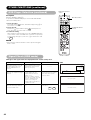
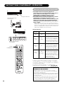
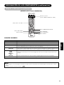
OPERATING INSTRUCTIONS
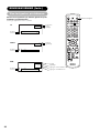
Indicating lamp
Main power switch
SUB-POWER button
STANDBY/ON
RECALL
TV
DVD
/I
i
+
AV 1 AV 2 AV 3 AV 4
AV 5
MENU
VOL PROG
A. MODE P. MODE
RETURN
AV 6 RGB 1 RGB 2
23
456
78
0
9
?
i
I/II
2-4-12
1
OK
+
P+
P
STANDBY/ON
button
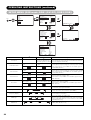
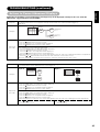
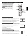
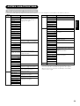
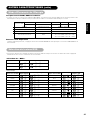
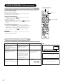
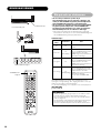
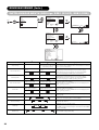
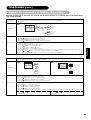
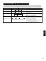
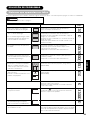
Tur ning Power On and Off
• To turn the monitor power ON, press the main power
switch on the monitor main unit to ON, and then press
the SUB POWER button of control panel or the
STANDBY/ON button on the remote control.
• To turn the monitor power off, press the SUB POWER
button of control panel or the STANDBY/ON button on
the remote control, and then press the main power
switch on the monitor main unit to OFF.
• During normal use, the main power switch is set in the ON
position, and the monitor can then be turned ON/OFF using the
SUB POWER button or the STANDBY/ON button on the remote
control.
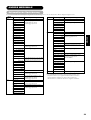
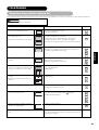
Indicating lamp
When the indicating lamp lights in orange or the message “No Sync.
Signal”, “Power Save” or “Invalid Scan Freq.” appears on the
screen, there is something unusual about the status of reception.
See “Power Save Mode” or “Symptoms That Seemingly Appear to
be Failures.”
ATTENTION
•Avoid repeatedly turning the monitor on and off at short time
intervals. Failures might result from such operation.
•Turn off the main power switch before leaving the monitor out of
use for an extended period of time.
• If a power failure occurs whilst the main unit is running, it wouild
be powered on upon recovery from the failure. Turn off the unit
main power switch before leaveing the main unit.
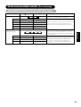
41 42
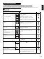
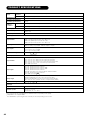
Indicating
lamp
Off
Lights red
Lights green
Lights orange
Power status
Off
Off
(standby)
On
Off
(Power Save)
Operating
When the main power switch is set
to OFF.
When the main power switch is
ON, and the STANDBY/ON button
on the remote control or the SUB
POWER button on the underside of
the front of the frame is OFF.
When the main power switch is
ON, and the STANDBY/ONbutton
on the remote control or the SUB
POWER button on the underside of
the front of the frame is ON.
When the main power switch is
ON, and the STANDBY/ON button
on the remote control or the SUB
POWER button on the underside of
the front of the frame is ON.
However, the state is in POWER
SAVE mode.
43

19
ENGLISH
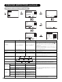
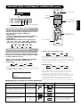
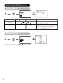
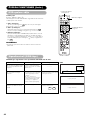
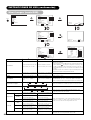
OPERATING INSTRUCTIONS (continued)
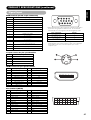
INPUT SELECT button
INPUT SELECT
buttons
PROGRAM
SELECT button
CHANNEL
UP/DOWN buttons
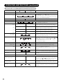
ZOOM button
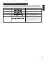
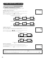
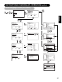
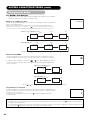
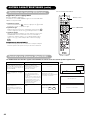
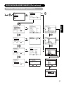
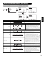
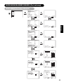
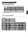
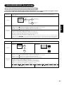
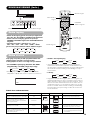
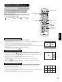
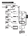
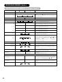
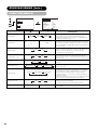
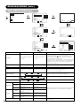
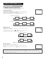
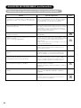
Input Switching
TV AV1 AV2 AV3 AV4
RGB2 RGB1 AV6 AV5
• Input can be switched by pressing the AV1~6, RGB1 or
RGB2 buttons of the remote control.
• Input can be switched to TV by pressing CHANNEL UP/
DOWN buttons or PROGRAM SELECT buttons.
• Input can be switched in the sequence of TV ➝ AV1 ➝
AV2 ➝ AV3 ➝ AV4 ➝ AV5 ➝ AV6 ➝ RGB1 ➝ RGB2 by
pressing the INPUT SELECT button of the control
panel.
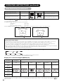
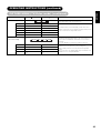
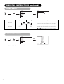
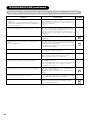
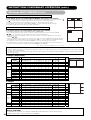
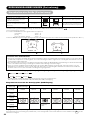
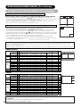
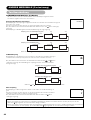
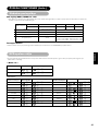
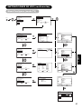
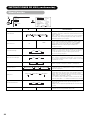
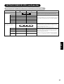
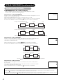
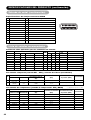
CHANNEL UP/DOWN buttons
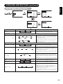
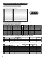
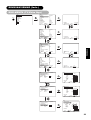
Each time the ZOOM button of the remote control is
pressed, the screen display size will change in sequence
and the status will be displayed at the bottom of the
screen.
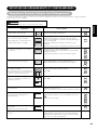
• During TV/VIDEO signal input (AV4, AV5, AV6, RGB1
(set to [DVI-STB]) and RGB2 (set to [Component])
• The size will fix as Full mode and not change when receiving
the component signal of 1080i/50, 1080i/60, 720p/50 or 720p/60.
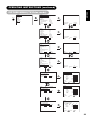
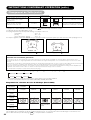
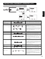
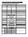
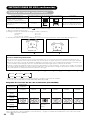
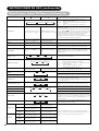
Display size selection diagram
Panoramic 4:3 Full
14:9Zoom C14:9L Zoom
Full
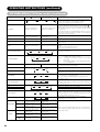
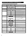
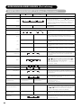
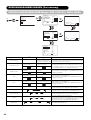
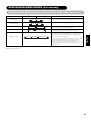
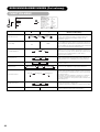
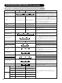
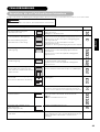
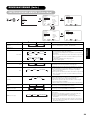
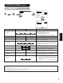
Size Switching
• During AV1~ AV3 signal input
• [Auto] is the mode using the Switch signal from the equipment
connected to AV1~AV3 terminal included in SCART connector
No.8 pin which indicate the picture format of the video source.
When Switch signal has not been detected, Default Zoom setting
in the Function Menu is used to choose.
• During TV mode
• [Auto] is the mode using WSS (Wide Screen Signals) which
identify the picture format movies and programs are broadcast in.
Various broadcast stations now transmit WSS. It can be detected
and the monitor automatically switch to the correct format.
However, some broadcasters do not transmit WSS, so this monitor
will not recognize which format is being transmitted. Therefore,
Default Zoom setting in the Function Menu is used to choose when
a WSS has not been sent or has not been detected.
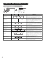
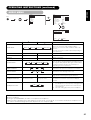
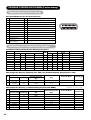
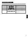
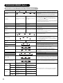
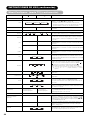
Play a 4:3 image in a 16:9 screen faithfully.
Play a 4:3 image in a 16:9 screen with the
height and width of the middle of the
screen enlarged on equal scales and with
both sides appearing somewhat enlarged.
Play a 16:9 VISTA size image from a 4:3
image faithfully reproduced on the 16:9
screen.
Play a 4:3 image faithfully in a 16:9 screen
in the standard vertical size and
horizontally squeezed.*
Blanking occurs on both sides.
•
The 4:3 image is called a letterbox image.
• In some cases, some slight blanking
may remain at the top and bottom.
* An image with an aspect ratio of 16:9
shrunk horizontally to 4:3 to display in a
4:3 screen
When you want to Set the display size Display screenInput signal Remarks
(4.:3 signal)
(Vista)
(Squeeze)
4 : 3
Panoramic
Zoom
Full
Auto Full Zoom
14:9Zoom C14:9L
Auto Full Zoom
14:9Zoom C14:9L
STANDBY/ON
RECALL
TV
DVD
/I
i
+
AV 1 AV 2 AV 3 AV 4
AV 5
MENU
VOL PROG
A. MODE P. MODE
RETURN
AV 6 RGB 1 RGB 2
23
456
78
0
9
?
i
I/II
2-4-12
1
OK
+
P
+
P
RECALL button
Page is loading ...
Page is loading ...
Page is loading ...
Page is loading ...
Page is loading ...
Page is loading ...
Page is loading ...
Page is loading ...
Page is loading ...
Page is loading ...
Page is loading ...
Page is loading ...
Page is loading ...
Page is loading ...
Page is loading ...
Page is loading ...
Page is loading ...
Page is loading ...
Page is loading ...
Page is loading ...
Page is loading ...
Page is loading ...
Page is loading ...
Page is loading ...
Page is loading ...
Page is loading ...
Page is loading ...
Page is loading ...
Page is loading ...
Page is loading ...
Page is loading ...
Page is loading ...
Page is loading ...
Page is loading ...
Page is loading ...
Page is loading ...
Page is loading ...
Page is loading ...
Page is loading ...
Page is loading ...
Page is loading ...
Page is loading ...
Page is loading ...
Page is loading ...
Page is loading ...
Page is loading ...
Page is loading ...
Page is loading ...
Page is loading ...
Page is loading ...
Page is loading ...
Page is loading ...
Page is loading ...
Page is loading ...
Page is loading ...
Page is loading ...
Page is loading ...
Page is loading ...
Page is loading ...
Page is loading ...
Page is loading ...
Page is loading ...
Page is loading ...
Page is loading ...
Page is loading ...
Page is loading ...
Page is loading ...
Page is loading ...
Page is loading ...
Page is loading ...
Page is loading ...
Page is loading ...
Page is loading ...
Page is loading ...
Page is loading ...
Page is loading ...
Page is loading ...
Page is loading ...
Page is loading ...
Page is loading ...
Page is loading ...
Page is loading ...
Page is loading ...
Page is loading ...
Page is loading ...
Page is loading ...
Page is loading ...
Page is loading ...
Page is loading ...
Page is loading ...
Page is loading ...
Page is loading ...
Page is loading ...
Page is loading ...
Page is loading ...
Page is loading ...
Page is loading ...
Page is loading ...
Page is loading ...
Page is loading ...
Page is loading ...
Page is loading ...
Page is loading ...
Page is loading ...
Page is loading ...
Page is loading ...
Page is loading ...
Page is loading ...
Page is loading ...
Page is loading ...
Page is loading ...
Page is loading ...
Page is loading ...
Page is loading ...
Page is loading ...
Page is loading ...
Page is loading ...
Page is loading ...
Page is loading ...
Page is loading ...
Page is loading ...
Page is loading ...
Page is loading ...
Page is loading ...
Page is loading ...
Page is loading ...
Page is loading ...
Page is loading ...
Page is loading ...
Page is loading ...
Page is loading ...
Page is loading ...
Page is loading ...
Page is loading ...
Page is loading ...
Page is loading ...
Page is loading ...
Page is loading ...
Page is loading ...
Page is loading ...
Page is loading ...
Page is loading ...
Page is loading ...
Page is loading ...
Page is loading ...
Page is loading ...
Page is loading ...
Page is loading ...
Page is loading ...
Page is loading ...
Page is loading ...
Page is loading ...
Page is loading ...
Page is loading ...
Page is loading ...
Page is loading ...
Page is loading ...
Page is loading ...
Page is loading ...
Page is loading ...
Page is loading ...
Page is loading ...
Page is loading ...
Page is loading ...
Page is loading ...
Page is loading ...
Page is loading ...
Page is loading ...
Page is loading ...
Page is loading ...
Page is loading ...
Page is loading ...
Page is loading ...
Page is loading ...
Page is loading ...
Page is loading ...
Page is loading ...
Page is loading ...
Page is loading ...
Page is loading ...
Page is loading ...
Page is loading ...
Page is loading ...
Page is loading ...
Page is loading ...
Page is loading ...
Page is loading ...
Page is loading ...
Page is loading ...
Page is loading ...
Page is loading ...
Page is loading ...
Page is loading ...
Page is loading ...
Page is loading ...
Page is loading ...
Page is loading ...
Page is loading ...
Page is loading ...
Page is loading ...
Page is loading ...
Page is loading ...
Page is loading ...
Page is loading ...
Page is loading ...
Page is loading ...
Page is loading ...
Page is loading ...
Page is loading ...
Page is loading ...
Page is loading ...
Page is loading ...
Page is loading ...
Page is loading ...
Page is loading ...
Page is loading ...
Page is loading ...
Page is loading ...
Page is loading ...
Page is loading ...
Page is loading ...
Page is loading ...
Page is loading ...
Page is loading ...
Page is loading ...
Page is loading ...
Page is loading ...
Page is loading ...
Page is loading ...
Page is loading ...
Page is loading ...
Page is loading ...
Page is loading ...
Page is loading ...
Page is loading ...
Page is loading ...
-
 1
1
-
 2
2
-
 3
3
-
 4
4
-
 5
5
-
 6
6
-
 7
7
-
 8
8
-
 9
9
-
 10
10
-
 11
11
-
 12
12
-
 13
13
-
 14
14
-
 15
15
-
 16
16
-
 17
17
-
 18
18
-
 19
19
-
 20
20
-
 21
21
-
 22
22
-
 23
23
-
 24
24
-
 25
25
-
 26
26
-
 27
27
-
 28
28
-
 29
29
-
 30
30
-
 31
31
-
 32
32
-
 33
33
-
 34
34
-
 35
35
-
 36
36
-
 37
37
-
 38
38
-
 39
39
-
 40
40
-
 41
41
-
 42
42
-
 43
43
-
 44
44
-
 45
45
-
 46
46
-
 47
47
-
 48
48
-
 49
49
-
 50
50
-
 51
51
-
 52
52
-
 53
53
-
 54
54
-
 55
55
-
 56
56
-
 57
57
-
 58
58
-
 59
59
-
 60
60
-
 61
61
-
 62
62
-
 63
63
-
 64
64
-
 65
65
-
 66
66
-
 67
67
-
 68
68
-
 69
69
-
 70
70
-
 71
71
-
 72
72
-
 73
73
-
 74
74
-
 75
75
-
 76
76
-
 77
77
-
 78
78
-
 79
79
-
 80
80
-
 81
81
-
 82
82
-
 83
83
-
 84
84
-
 85
85
-
 86
86
-
 87
87
-
 88
88
-
 89
89
-
 90
90
-
 91
91
-
 92
92
-
 93
93
-
 94
94
-
 95
95
-
 96
96
-
 97
97
-
 98
98
-
 99
99
-
 100
100
-
 101
101
-
 102
102
-
 103
103
-
 104
104
-
 105
105
-
 106
106
-
 107
107
-
 108
108
-
 109
109
-
 110
110
-
 111
111
-
 112
112
-
 113
113
-
 114
114
-
 115
115
-
 116
116
-
 117
117
-
 118
118
-
 119
119
-
 120
120
-
 121
121
-
 122
122
-
 123
123
-
 124
124
-
 125
125
-
 126
126
-
 127
127
-
 128
128
-
 129
129
-
 130
130
-
 131
131
-
 132
132
-
 133
133
-
 134
134
-
 135
135
-
 136
136
-
 137
137
-
 138
138
-
 139
139
-
 140
140
-
 141
141
-
 142
142
-
 143
143
-
 144
144
-
 145
145
-
 146
146
-
 147
147
-
 148
148
-
 149
149
-
 150
150
-
 151
151
-
 152
152
-
 153
153
-
 154
154
-
 155
155
-
 156
156
-
 157
157
-
 158
158
-
 159
159
-
 160
160
-
 161
161
-
 162
162
-
 163
163
-
 164
164
-
 165
165
-
 166
166
-
 167
167
-
 168
168
-
 169
169
-
 170
170
-
 171
171
-
 172
172
-
 173
173
-
 174
174
-
 175
175
-
 176
176
-
 177
177
-
 178
178
-
 179
179
-
 180
180
-
 181
181
-
 182
182
-
 183
183
-
 184
184
-
 185
185
-
 186
186
-
 187
187
-
 188
188
-
 189
189
-
 190
190
-
 191
191
-
 192
192
-
 193
193
-
 194
194
-
 195
195
-
 196
196
-
 197
197
-
 198
198
-
 199
199
-
 200
200
-
 201
201
-
 202
202
-
 203
203
-
 204
204
-
 205
205
-
 206
206
-
 207
207
-
 208
208
-
 209
209
-
 210
210
-
 211
211
-
 212
212
-
 213
213
-
 214
214
-
 215
215
-
 216
216
-
 217
217
-
 218
218
-
 219
219
-
 220
220
-
 221
221
-
 222
222
-
 223
223
-
 224
224
-
 225
225
-
 226
226
-
 227
227
-
 228
228
-
 229
229
-
 230
230
-
 231
231
-
 232
232
-
 233
233
-
 234
234
-
 235
235
-
 236
236
-
 237
237
-
 238
238
-
 239
239
-
 240
240
-
 241
241
-
 242
242
-
 243
243
-
 244
244
-
 245
245
-
 246
246
-
 247
247
-
 248
248
-
 249
249
-
 250
250
-
 251
251
-
 252
252
-
 253
253
-
 254
254
-
 255
255
-
 256
256


Ask a question and I''ll find the answer in the document
Finding information in a document is now easier with AI
in other languages
- français: Yamaha PDM-4220 Le manuel du propriétaire
- español: Yamaha PDM-4220 El manual del propietario
- Deutsch: Yamaha PDM-4220 Bedienungsanleitung
- svenska: Yamaha PDM-4220 Bruksanvisning
Related papers
-
Yamaha PDM-4210E Owner's manual
-
-
-
-
-
-
-
-
-