Miller
April
1995
Form:
OM-1583G
Effective
With
Serial
No.
KF844784
OWNERS
MANUAL
U
Read
and
follow
these
instructions
and
all
safety
blocks
carefully.
Have
only
trained
and
qualified
persons
install,
operate,
or
service
this
unit.
Call
your
distributor
if
you
do
not
understand
the
directions.
.A
Give
this
manual
to
the
operator.
For
help,
call
your
distributor
or
MILLER
Electric
Mfg.
Co.,
P0.
Box
1079,
Appleton,
WI
54912
414-734-9821
&
SWINGARCTM
SS-12
And
SS-16
24
Volts,
10
Amperes,
50/60
Hertz
Boom
Mounted
Wire
Feeder
For
Use
With
CV/DC
Welding
Power
Source
With
Contactor
For
GMAW
And
FCAW
Welding
Rated
At
100
Volts,
750
Amperes,
100%
Duty
Cycle
Wire
Feed
Speed
Range:
50
To
780
ipm
(1.3
To
19.8
mpm)
Wire Diameter
Range:
.023
To
1/8
in
(0.6
To
3.2
mm)
Vertical
Lift
Of
Boom:
Horizontal
To
60
Above
Horizontal
For
Options
And
Accessories,
See
Rear
Cover
cover
5/94
ST-142
705-B
'
1995
MILLER
Electiic
Mfg.
Co.
PRINTED
IN
USA

I
tax
Effective
January
1,
1995
(Equipment
with
a
serial
number
preface
of
KD
or
newer)
This
limited
warranty
supersedes
all
previous
MILLER
warranties
and
is
exclusive
with
no
other
guarantees
or
warranties
expressed
or
implied.
LIMITED
WARRANTY
Subject
to
the
terms
and
conditions
below,
MILLER
Electric
Mtg.
Co.,
Appleton,
Wisconsin,
warrants
to
its
original
retail
purchaser
that
new
MILLER
equipment
sold
after
the
effective
date
of
this
limited
warranty
is
free
of
de
tests
in
material
and
workmanship
at
the
time
it
is
shipped
by
MILLER.
THIS
WAR
RANTY
IS
EXPRESSLY
IN
LIEU
DF
ALL
OThER
WARRAN11ES,
EXPRESS
DR
IMPUED,
INCLUDING
THE
WARRAN11ES
OF
MERCHANTABIUTY
AND
FIT
NESS.
Within
the
warranty
periods
listed
below,
MILLER
will
repair
or
replace
any
war
ranted
parts
or
components
that
fail
due
to
such
defects
in
material
or
workmanship.
MILLER
must
be
notified
in
writing
within
thirty
(30)
days
of
such
detect
or
failure,
at
which
time
MILLER
will
provide
instructions
on
the
warranty
claim
procedures
to
be
followed.
MILLER
shall
honor
warranty
claims
on
warranted
equipment
listed
below
in
the
event
of
such
a
failure
within
the
warranty
time
periods.
All
warranty
time
periods
start
on
the
date
that
the
equipment
was
delivered
to
the
original
retail
purchaser,
or
one
year
after
the
equipment
is
sent
to
a
North
American
distributor
or
eighteen
months
after
the
equipment
is
sent
to
an
Intemational
distributor.
1.
SYearaParts3YearsLabor
Original
main
power
rectifiers
2.
3
Years
Parts
and
Labor
Transformer/Rectifier
Power
Sources
Plasma
Arc
Cutting
Power
Sources
*
Semi-Automatic
and
Automatic
Wire
Feeders
*
Robots
3.
2
Years
Parts
and
Labor
Engine
Driven
Welding
Generators
(NOTE:
Engines
are
warranted
separately
by
the
engine
manufacturer.)
Air
Compressors
4.
1
Year
Parts
and
Labor
Motor
Driven
Guns
*
Process
Controllers
IHPS
Power
Sources
*
Water
Coolant
Systems
*
HFUnils
Grids
Spot
Welders
*
Load
Banks
SDX
Transformers
Running
Gear/Trailers
Plasma
Cutting
Torches
(except
APT,
ZIPCUT
&
PLAZCUT
Models)
Tecumaeh
Engines
Deutz
Engines
(outside
North
America)
Field
Options
(NOTE:
Field
options
are
covered
under
True
BtueTM
for
the
remaining
warranty
period
of
the
product
they
are
installed
in,
or
for
a
minimum
of
one
year
whichever
is
greater.)
5.
6
Months
Batteries
a]
6.
90
Days
Parts
and
Labor
HG
Guns/tlG
Torches
APT,
ZIPCUT
&
PLAZCUT
Model
Plasma
Cutting
Torches
Remote
Controls
Accessory
Kits
Replacement
Parts
MILLERS
True
BIueTM
Umited
Warranty
shall
not
apply
to:
1.
items
fumished
by
MILLER,
but
manufactumd
by
others,
such
as
engines
or
trade
accessories.
These
items
are
covered
by
the
manufacturers
warranty,
if
any.
2.
Consumable
components;
such
as
contact
tips,
cutting
nozzles,
contactors
and
relays
or
parts
that
fail
due
to
normal
wear.
3.
Equipment
that
has
been
modified
by
any
party
other
than
MILLER,
or
equip
ment
that
has
been
improperty
installed,
improperiy
operated
or
misused
based
upon
industry
standards,
or
equipment
which
has
not
had
reasonable
and
necessary
maintenance,
orequipment
which
has
been
used
for
operation
outside
of
the
specifications
for
the
equipment.
MILLER
PRODUCTS
ARE
INTENDED
FOR
PURCHASEAND
USE
BYCOMMER
CIAL?1NDUSTRIAL
USERS
AND
PERSONS
TRAINED
AND
EXPERIENCED
IN
THE
USE
AND
MAINTENANCE
OF
WELDING
EOUIPMENt
in
the
event
of
a
warranty
claim
covered
by
this
warranty,
the
exclusive
remedies
shall
be,
at
MILLERS
option:
(1)
repair,
or
(2)
replacement;
or,
where
authorized
in
writing
by
MILLER
in
appropriate
cases,
(3)
the
reasonable
cost
of
repair
or
replace
ment
at
an
authorized
MILLER
service
station;
or
(4)
payment
of
orcredit
forthe
pur
chase
price
(less
reasonable
depreciation
based
upon
actual
use)
upon
mtum
of
the
goods
at
customers
risk
and
expense.
MILLERS
option
of
repair
or
replacement
will
be
FOB.,
Factonj
at
Appleton,
Wisconsin,
or
FOB.
ate
MILLER
authorized
ser
vice
facility
as
determined
by
MILLER.
Therefore
no
compensation
or
reimburse
ment
for
transportation
costs
of
any
kind
will
be
allowed.
TO
THE
EXTENT
PERMITTED
BY
LAW,
THE
REMEDIES
PROVIDED
HEREIN
ARE ThE
SOLE
AND
EXCLUSIVE
REMEDIES.
IN
NO
EVENT
SHALL
MILLER
BE
UABLE
FOR
DIRECT,
INDIRECT,
SPECIAL,
INCIDENTALOR
CONSEOUENTIAL
DAMAGES
(INCLUDING
LOSS
OF
PROFIT),
WHETHER
BASED
ON
CON
TRACT,
TORT
OR
ANY
OTHER
LEGAL
THEORY.
ANY
EXPRESS
WARRANTY
NOT
PROVIDED
HEREIN
AND
ANY
IMPLIED
WAR
RANTY,
GUARANTY
OR
REPRESENTA11ON
ASTO
PERFORMANCE,
AND ANY
REMEDY
FOR
BREACH
OF
CONTRACT
TORT
OR
ANY
OTHER
LEGAL
THEORY
WHICH,
BUT
FOR
THIS
PROVISION,
MIGI-fT
ARISE
BY
IMPUCA11ON,
OPERA11ON
OF
LAW,
CUSTOM
OF
TRADE
OR
COURSE
OF
DEALING,
IN
CLUDING
ANY
IMPLIED
WARRANTY
OF
MERCHANTABILITY
OR
FITNESS
FOR
PARTICULAR
PURPOSE,
WITH
RESPECT
10
ANY
AND
ALL
EOUIPMENT
FURNISHED
BY
MILLER
IS
EXCLUDED
AND
DISCLAIMED
BY
MILLER.
Some
states
in
the
U.S.A.
do
not
allow
timitations
of
how
long
an
implied
warranty
lasts,
or
the
exclusion
of
incidental,
indirect,
special
or
consequential
damages,
so
the
above
limitation
or
exclusion
may
not
apply
to
you.
This
warranty
provides
spe
cific
legal
rights,
and
other
rights
may
be
available,
but
may
vary
from
state
to
state.
In
Conads,
legislation
in
some
provinces
provides
for
certain
additional
warranties
or
remedies
other
than
as
stated
herein,
and
to
the
extent
that
they
may
not
be
waived,
the
limitations
and
exclusions
set
out
above
may
not
apply.
This
Limited
Warranty
provides
specific
legal
rights,
and
other
rights
may
be
available,
but
may
~~very
from
province
to
province.
RECEIVING-HANDLING
Before
unpaCk(ng
equipment,
check
carton
for
any
damage
that
may
have
occurred
during
sh)pment.
Fi(e
any
claims
for
loss
or
damage
with
the
delivering
carrier
Assistance
(or
filing
or
settling
claims
may
be
obtained
from
distributor
and/or
equipment
manufacturers
Transportation
Department.
When
requesting
information
about
this
equipment,
always
provide
Model
Designation
and
Serial
or
Style
Number.
Use
the
following
spaces
to
record
Model
Designation
and
Serial
or
Style
Numberof
your
unit.
The
information
is
located
on
the
rating
label
or
nameplate.
Model
_________
Serial
or
Style
No.
Date
of
Purchase
J
MILLERS
TRUE
BLUETM
LIMITED
WARRANTY
I
1~.
miller
4/95
ARC
WELDING
SAFETY
PRECAUTIONS
ELECTRIC
SHOCK
can
kill.
Touching
live
electrical
parts
can
cause
fatal
shocks
or
severe
bums.
The
electrode
and
work
circuit
is
electrically
live
whenever
the
output
is
on.
The
input
power
circuit
and
machine
internal
circuits
are
also
live
when
power
is
on.
In
semiautomatic
or
automatic
wire
welding,
the
wire,
wire
reel,
drive
roll
housing,
and
all
metal
parts
touching
the
welding
wire
are
electrically
live.
Incorrectly
installed
or
improperly
grounded
equipment
is
a
hazard.
1.
Do
not
touch
live
electrical
parts.
2.
Wear
dry,
hole-free
insulating
gloves
and
body
protection.
3.
Insulate
yourself
from
work
and
ground
using
dry
insulating
mats
or
covers
big
enough
to
prevent
any
physical
contact
with
the
work
or
ground.
4.
Disconnect
input
power
or
stop
engine
before
installing
or
servicing
this
equipment.
Lockout/tagout
input
poweraccording
to
OSHA
29
CFR
1910.147
(see
Safety
Standards).
5.
Properly
install
and
ground
this
equipment
according
to
its
Owners
Manual
and
national,
state,
and
local
codes.
6.
Always
verify
the
supply
ground
check
and
be
sure
that
input
power
cord
ground
wire
is
properly
connected
to
ground
ARC
RAYS
can
burn
eyes
and
skin;
NOISE
can
damage
hearing;
FLYING
SLAG
OR
SPARKS
can
injure
eyes.
Arc
rays
from
the
welding
process
produce
intense
visible
and
invisible
(ultraviolet
and
infrared)
rays
that
can
burn
eyes
and
skin.
Noise
from
some
processes
can
damage
hearing.
Chipping,
grinding,
and
welds
cooling
throw
off
pieces
of
metal
or
slag.
1.
Keep
your
head
out
of
the
fumes.
Do
not
breathe
the
fumes.
2.
If
inside,
ventilate
the
area
and/or
use
exhaust
at
the
arc
to
remove
welding
fumes
and
gases.
3.
If
ventilation
is
poor,
use
an
approved
air-supplied
respirator.
4.
Read
the
Material
Safety
Data
Sheets
(MSDSs)
and
the
manufacturer~s
instruction
for
metals,
consumables,
coatings,
cleaners,
and
degreasers.
terminal
in
disconnect
box
or
that
cord
plug
is
connected
to
a
properly
grounded
receptacle
outlet.
7.
When
making
input
connections,
attach
proper
grounding
conductor
first
double-check
connections.
8.
Frequently
inspect
input
powercord
fordamage
or
bare
wiring
replace
cord
immediately
if
damaged
bare
wiring
can
kill.
9.
Turn
off
all
equipment
when
not
in
use.
10.
Do
not
use
worn,
damaged,
undersized,
or
poorly
spliced
cables.
11.
Do
not
drape
cables
over
your
body.
12.
If
earth
grounding
of
the
workpiece
is
required,
ground
it
directly
with
a
separate
cable
do
not
use
work
clamp
or
work
cable.
13.
Do
not
touch
electrode
if
you
are
in
contact
with
the
work,
ground,
or
another
electrode
from
a
different
machine.
14.
Use
only
well-maintained
equipment.
Repair
or
replace
damaged
parts
at
once.
Maintain
unit
according
to
manual.
Wear
a
safety
harness
if
working
above
floor
level.
Keep
all
panels
and
covers
securely
in
place.
Clamp
work
cable
with
good
metal-to-metal
contact
to
workpiece
or
worktable
as
near
the
weld
as
practical.
ARC
RAYS
2.
Wear
a
welding
helmet
fitted
with
a
proper
shade
of
filter
to
protectyourface
and
eyes
when
welding
orwatching
(see
ANSI
Z49.1
and
Z87.1
listed
in
Safety
Standards).
Wear
approved
safety
glasses
with
side
shields.
Use
protective
screens
or
bamers
to
protect
others
from
flash
and
glare;
warn
others
not
to
watch
the
arc.
5.
Wear
protective
clothing
made
from
durable,
flame-resistant
material
(wool
and
leather)
and
foot
protection.
5.
Work
in
a
confined
space
only
if
it
is
well
ventilated,
or
while
wearing
an
air-supplied
respirator.
Always
have
a
trained
watchperson
nearby.
Welding
fumes
and
gases
can
displace
air
and
lower
the
oxygen
level
causing
injury
or
death.
Be
sure
the
breathing
air
is
safe.
6.
Do
not
weld
in
locations
near
degreasing,
cleaning,
or
spraying
operations.
The
heat
and
rays
of
the
arc
can
react
with
vapors
to
form
highly
toxic
and
irritating
gases.
7.
Do
not
weld
on
coated
metals,
such
as
galvanized,
lead,
or
cadmium
plated
steel,
unless
the
coating
is
removed
from
the
weld
area,
the
area
is
well
ventilated,
and
if
necessary,
while
wearing
an
air-supplied
respirator.
The
coatings
and
any
metals
containing
these
elements
can
give
off
toxic
fumes
if
welded.
a
WARNING
ARC
WELDING
can
be
hazardous.
PROTECT
YOURSELF
AND
OTHERS
FROM
POSSIBLE
SERIOUS
INJURY
OR
DEATH.
KEEP
CHILDREN
AWAY.
PACEMAKER
WEARERS
KEEP
AWAY
UNTIL
CONSULTING
YOUR
DOCTOR.
In
welding,
as
in
most
jobs,
exposure
to
certain
hazards
occurs.
Welding
is
safe
when
precautions
are
taken.
The
safety
information
given
below
is
only
a
summary
of
the
more
complete
safety
information
that
will
be
found
in
the
Safety
Standards
listed
on
the
next
page.
Read
and
follow
all
Safety
Standards.
HAVE
ALL
INSTALLATION,
OPERATION,
MAINTENANCE,
AND
REPAIR
WORK
PERFORMED
ONLY
BY
QUALIFIED
PEOPLE.
I
15.
16.
17.
:~k~
NOISE
3.
4.
ear
plugs
or
ear
muffs
if
noise
level
is
high.
s-s
FUMES
AND
GASES
can
be
hazardous
to
your
health.
Welding
produces
fumes
and
gases.
Breathing
these
fumes
and
gases
can
be
hazardous
to
your
health.
CYLINDERS
can
explode
if
damaged.
4.
Never
drape
a
welding
torch
over
a
gas
cylinder.
Shielding
gas
cylinders
contain
gas
under
high
5.
Never
allow
a
welding
electrode
to
touch
any
cylinder.
pressure.
If
damaged,
a
cylinder
can
explode.
Since
6.
Never
weld
on
a
pressurized
cylinder
explosion
will
result.
gas
cylinders
are
normally
part
of
the
welding
process,
be
sure
to
treat
them
carefully.
7.
Useonlycorrectshieldinggascylinders,
regulators,
hoses,
and
fittings
designed
for
the
specific
application;
maintain
them
and
associated
parts
in
good
condition.
1.
Protect
compressed
gas
cylinders
from
excessive
heat,
8.
Turn
face
away
from
valve
outlet
when
opening
cylinder
valve.
mechanical
shocks,
slag,
open
flames,
sparks,
and
arcs.
9.
Keepprotectivecapinplaceovervalveexceptwhencylinderis
2.
Install
cylinders
in
an
upright
position
by
securing
to
a
stationary
in
use
or
connected
for
use.
support
or
cylinder
rack
to
prevent
falling
or
tipping.
io.
Read
and
follow
instructions
on
compressed
gas
cylinders,
3.
Keep
cylinders
away
from
any
welding
or
other
electrical
associated
equipment,
and
CGA
publication
P-i
listed
in
Safety
circuits.
Standards.
srl.1.1
2/94
WELDING
can
cause
fire
or
explosion.
Welding
on
closed
containers,
such
as
tanks,
drums,
or
pipes,
can
cause
them
to
blow
up.
Sparks
can
fly
off
from
the
welding
arc.
The
flying
sparks,
hot
workpiece,
and
hot
equipment
can
cause
fires
and
burns.
Accidental
contact
of
electrode
to
metal
objects
can
cause
sparks,
explosion,
overheating,
or
fire.
Check
and
be
sure
the
area
is
safe
before
doing
any
welding.
1.
Protect
yourself
and
others
from
flying
sparks
and
hot
metal.
2.
Do
not
weld
where
flying
sparks
can
strike
flammable
material.
3.
Remove
all
flammables
within
35
ft
(10.7
m)
of
the
welding
arc.
If
this
is
not
possible,
tightly
cover
them
with
approved
covers.
4.
Be
alert
that
welding
sparks
and
hot
materials
from
welding
can
easily
go
through
small
cracks
and
openings
to
adjacent
areas.
5.
Watch
for
fire,
and
keep
a
fire
extinguisher
nearby.
SPARKS
can
cause
BATTERY
GASES
TO
EXPLODE;
BATTERY
ACID
can
burn
eyes
and
skin.
Batteries
contain
acid
and
generate
explosive
gases.
STEAM
AND
PRESSURIZED
HOT
COOLANT
can
burn
face,
eyes,
and
skin.
It
is
best
to
check
coolant
level
when
engine
is
cold
to
avoid
scalding.
6.
Be
aware
that
welding
on a
ceiling,
floor,
bulkhead,
or
partition
can
cause
fire
on
the
hidden
side.
7.
Do
not
weld
on
closed
containers
such
as
tanks,
drums,
or
pipes,
unless
they
are
properly
prepared
according
to
AWS
F4.1
(see
Safety
Standards).
8.
Connect
work
cable
to
the
work
as
close
to
the
welding
area
as
practical
to
prevent
welding
current
from
traveling
long,
possibly
unknown
paths
and
causing
electric
shock
and
fire
hazards.
9.
Do
not
use
welder
to
thaw
frozen
pipes.
10.
Remove
stick
electrode
from
holder
or
cut
oft
welding
wire
at
contact
tip
when
not
in
use.
11.
Wear
oil-free
protective
garments
such
as
leather
gloves,
heavy
shirt,
cuffless
trousers,
high
shoes,
and
a
cap.
12.
Remove
any
combustibles,
such
as
a
butane
lighter
or
matches,
from
your
person
before
doing
any
welding.
Always
wear
a
face
shield
when
working
on
a
battery.
Stop
engine
before
disconnecting
or
connecting
battery
cables.
3.
Do
not
allow
tools
to
cause
sparks
when
working
on
a
battery.
Do
not
use
welder
to
charge
batteries
or
jump
start
vehicles.
Observe
correct
polarity
(+
and
)
on
batteries.
1.
If
the
engine
is
warm
and
checking
is
needed,
follow
steps
2
and
3.
2.
Wear
safety
glasses
and
gloves
and
put
a
rag
over
cap.
3.
Tum
cap
slightly
and
let
pressure
escape
slowly
before
completely
removing
cap.
PRINCIPAL
SAFETY
STANDARDS
Safety
in
Welding
and
Cutting,
ANSI
Standard
Z49.
1,
from
American
Welding
Society,
550
N.W.
LeJeune
Ad,
Miami
FL
33126
Safety
and
Health
Standards,
OSHA
29
CFR
1910,
from
Superinten
dent
of
Documents,
U.S.
Government
Printing
Office,
Washington,
D.C.
20402.
Recommended
Safe
Practices
for
the
Preparation
for
Welding
and
Cutting
of
Containers
That
Have
Held
Hazardous
Substances,
Ameri
can
Welding
Society
Standard
AWS
F4.1,from
American
Welding
So
ciety,
550
NW.
LeJeune
Ad,
Miami,
FL
33126
National
Electrical
Code,
NFPA
Standard
70,
from
National
Fire
Pro
tection
Association,
Batterymarch
Park,
Quincy,
MA
02269.
Safe
Handling
of
Compressed
Gases
in
Cylinders,
CGA
Pamphlet
P-i,
from
Compressed
Gas
Association,
1235
Jefterson
Davis
High
way,
Suite
501,
Arlington,
VA
22202.
Code
for
Safety
in
Welding
and
Cutting,
CSA
Standard
Wi
17.2,
from
Canadian
Standards
Association,
Standards
Sales,
178
Rexdale
Bou
levard,
Rexdale,
Ontario,
Canada
M9W
1
R3.
Safe
Practices
ForOccupationAnd
Educational
EyeAnd
Face
Protec
tion,
ANSI
Standard
Z87.l,
from
American
National
Standards
Institute,
1430
Broadway,
New
York,
NY
10018.
Cutting
And
Welding
Processes,
NFPA
Standard
51
B,
from
National
Fire
Protection
Association,
Batterymarch
Park,
Quincy,
MA
02269.
£~
WARNING
ENGINES
can
be
hazardous.
ENGINE
EXHAUST
GASES
can
kill.
1.
Use
equipment
outside
in
open,
well-ventilated
areas.
Engines
produce
harmful
exhaust
gases.
2.
If
used
in
a
closed
area,
vent
engine
exhaust
outside
and
away
from
any
building
air
intakes.
ENGINE
FUEL
can
cause
fire
or
explosion.
3.
4.
A
Engine
fuel
is
highly
flammable.
1.
2.
Stop
engine
and
let
it
cool
off
before
checking
or
adding
fuel.
Do
not
add
fuel
while
smoking
or
if
unit
is
near
any
sparks
or
open
flames.
Do
not
overfill
tank
allow
room
for
fuel
to
expand.
Do
not
spill
fuel.
If
fuel
is
spilled,
clean
up
before
starting
engine.
~
MOVING
PARTS
can
cause
injury.
Moving
parts,
such
as
fans,
rotors,
and
belts
can
cut
fingers
and
hands
and
catch
loose
clothing.
1.
Keep
all
doors,
panels,
covers,
and
guards
closed
and
securely
in
place.
2.
Stop
eng
ne
before
installing
or
connecting
unit.
3.
Have
only
qualified
people
remove
guards
or
covers
for
maintenance
and
troubleshooting
as
necessary.
4.
To
prevent
accidental
starting
during
servicing,
disconnect
negative
()
battery
cable
from
battery.
5.
Keep
hands,
hair,
loose
clothing,
and
toots
awayfrom
moving
parts.
6.
Reinstall
panels
or
guards
and
close
doors
when
servicing
is
finished
and
before
starting
engine.
1.
2.
4.
5.
sIll
.1
2/94
CONSIGNES
DE
SECURITE
POUR
LE
SOUDAGE
A
LARC
UN
CHOC
ELECTRIQUE
peut
tuer.
Un
simple
contact
avec
des
piŁces
Ølectriques
peut
provoquer
une
electrocution
ou
des
blessures
graves.
Lelectrode
et
le
circuit
de
soudage
sont
sous
tension
des
que
lappareil
est
surON.
Le
circuit
dentrŁe
et
les
circuits
intemes
de
lappareil
sont
egalement
sous
tension
a
ce
moment-l.
En
soudage
semi-automatique
ou
automatique,
le
fil,
le
devidoir,
le
logement
des
galets
dentrainement
et
les
piŁces
mŁtalliques
en
contact
avec
le
fil
de
soudage
sont
sous
tension.
Des
matŁriels
mal
installŁs
ou
mal
mis
a
Ia
terre
presentent
un
danger.
1.
Ne
jamais
toucher
les
piŁces
Łlectriques
sous
tension.
2.
Porter
des
gants
et
des
vŁtements
de
protection
secs
ne
comportant
pas
de
trous.
3.
Sisoler
de
Ia
piŁce
et
de
Ia
terre
au
moyen
de
tapis
ou
dautres
moyens
isolants
suffisamment
grands
pour
empŁcher
le
contact
physique
Łventuel
avec
Ia
piŁce
ou
Ia
terre.
4.
Couper
lalimentation
ou
arrŁter
le
moteur
avant
de
proceder
a
linstallation,
a
Ia
reparation
ou
a
lentretien
de
lappareil.
DŁverrouiller
lalimentation
selon
Ia
norme
OSHA
29
CPA
1910.147
(voir
norrnes
de
sŁcuritŁ).
5.
Installer
et
mettre
ala
terre
correctement
cet
appareil
confomiement
a
son
manuel
dutilisation
et
au
codes
nationaux,
provinciaux
et
municipaux.
6.
Toujours
verifier
Ia
terre
du
cordon
dalimentation
Verifier
et
que
le
fil
de
terre
du
cordon
dalimentation
est
bien
LE
RAYONNEMENT
DE
LARC
peut
brler
les
yeux
et
Ia
peau.
Le
BRUIT
peut
endommager
IouIe;
les
PROJECTIONS
DE
LAITIER
OU
LES
ETINCELLES
peuvent
blesser
les
yeux.
Larc
de
soudage
produit
des
rayons
visibles
et
invisibles
intenses
(ultraviolets
et
infrarouges)
qui
peuvent
brOler
les
yeux
et
Ia
peau.
Le
bruit
produit
par
certains
procŁdŁs
peut
endommager
loute.
Des
projections
de
metal
ou
de
laitier
sont
produites
par
le
piquage,
le
meulage
ou
le
refroidissement
des
soudures.
Utiliserdes
bouche-oreilles
ou
des
serre-tŁte
antibruit
approuves
si
le
niveau
de
bruit
est
ŁlevŁ.
LES
VAPEURS
rr
LES
FUMEES
peuvent
Œtre
dangereuses
pour
Ia
sante.
1.
Garder
Ia
tŁte
a
IextŁrieur
des
vapeurs
et
des
fumŁes
et
ne
pas
les
respirer.
2.
A
lintŁrieur,
ventiler
le
poste
de
travail
ou
utiliser
un
dispositif
place
au
niveau
de
lam
pour
Łvacuer
les
vapeurs
et
fumŁes
de
soudage.
3.
Si
Ia
ventilation
est
mauvaise,
utiliser
un
appareil
respiratoire
a
adduction
dair
pur
approuve.
4.
Consulter
les
fiches
signaletiques
et
les
consignes
du
fabricant
relatives
au
metaux,
produits
dapport,
revŁtements,
nettoyants
et
dŁgraissants.
LES
BOUTEILLES
peuvent
expioser
Si
eVes
sont
endommagØes.
Les
bouteilles
contenant
des
gaz
de
protection
sont
a
haute
pres~ion.
Une
bouteille
endommagŁe
peut
exploser.
Etant
donne
que
les
bouteilles
de
gaz
font
normalement
partie
du
materiel
de
soudage,
les
traiter
___________
avec
le
plus
grand
soin.
1.
ProtŁger
Ies
bouteilles
de
gaz
comprime
contra
Ia
chateur
intense,
les
chocs,
Ie
laitier,
les
ftammes
nues,
les
Łtincelles
et
larc.
2.
Placer
les
bouteilles
ala
verticale
en
les
fixant
a
un
support
fixe
ou
a
un
chariot
pour
evfter
quelles
ne
tombeni
ou
ne
bascutent.
3.
Tenir
les
bouteilles
a
Iecart
du
poste
de
soudage
ou
dautres
circuits
Łlectriques.
raccorde
ala
bome
de
terre
du
sectionneurou
que
Ia
fiche
du
cordon
est
raccordŁe
a
une
prise
correctement
mise
a
Ia
terre.
7.
En
effectuant
les
raccordements
dentrŁe
fixer
dabord
le
conducteur
de
mise
a
Ia
terre
appropriŁ
et
contre-vŁrifier
es
connexions.
8.
VerifierfrŁquemment
le
cordon
dalimentation
pour
voir
sil
nest
pas
endommagŁ
ou
dŁnudŁ
remplacer
le
cordon
immŁdiatement
siI
est
endommagŁ
un
cable
dŁnudŁ
peut
provoquer
une
electrocution.
9.
Mettre
lappareil
hors
tension
quand
on
ne
Iutilise
pas.
10.
Ne
pas
utiliser
des
cables
uses,
endommagŁs,
de
grosseur
insuffisante
ou
mal
ŁpissŁs.
11.
Ne
pas
enrouler
les
cables
autour
du
corps.
12.
Si
Ia
piŁce
soudŁe
doit
Łtre
mise
ala
terre,
le
faire
directement
avec
un
cable
distinct
ne
pas
utiliser
le
connecteur
de
piŁce
ou
le
cable
de
retour.
13.
Ne
pas
toucher
IŁlectrode
quand
on
est
en
contact
avec
Ia
piŁce,
Ia
terre
ou
une
electrode
provenant
dune
autre
machine.
14.
Nutiliser
quun
materiel
en
bon
Łtat.
RŁparer
ou
remplacer
sur-le-champ
les
piŁces
endommagŁes.
Entretenir
Iappareil
conformŁment
a
ce
manuel.
15.
Porter
un
hamais
de
securite
quand
on
travaille
en
hauteur.
16.
Maintenir
solidement
en
place
tousles
panneaux
et
capots.
17.
Fixer
le
cable
de
retourde
faon
aobtenir
un
bon
contact
metal-metal
avec
Ia
piŁce
a
souderou
latable
detravail,
le
plus
prŁs
possible
de
Ia
soudure.
RAVONNEMENT
DE
LARC
2.
Porter
un
masque
a
serre-tete
muni
dun
verre
filtrant
de
nuance
appropriŁe
pour
proteger
le
visage
et
les
yeux
quand
on
soude
ou
observe
Ia
travail
de
soudage
(voir
les
normes
ANSI
Z49.1
et
Z87.1
donnees
sous
Ia
rubrique
Principales
normes
de
securite).
Porter
des
lunettes
de
sŁcurite
approuvees
avec
ecrans
Iateraux.
Utiliser
des
paravents
ou
des
barriŁres
de
protection
pour
proteger
les
personnes
a
proximitŁ
contra
les
coups
dam
et
Ieblouissement;
avertir
les
autres
personnes
de
ne
pas
regarder
larc.
5.
Porter
des
vOtements
de
protection
en
tissu
ignifuge
durable
(lame
et
cuir)
et
des
chaussures
de
securitŁ.
5.
Ne
travailler
dans
un
espace
confine
que
sil
est
bien
ventile,
ou
en
portant
un
appareil
respiratoire
a
adduction
dairpur.
Demander
a
un
observateur
ayant
reu
Ia
bonne
formation
de
toujours
se
tenir
a
proximite.
Les
vapeurs
et
fumŁes
de
soudage
peuvent
dŁplacer
Iair
et
abaisser
le
niveau
doxygŁne
et
causerdes
blessures
gravesvoire
mortelles.
Sassurer
que
Iair
est
propre
a
Ia
respiration.
6.
Ne
pas
souder
~
proximite
dopŁrations
de
dŁgraissage,
de
nettoyage
ou
de
pulvŁrisation.
La
chaleur
et
les
rayons
de
lam
peuvent
reagir
avec
les
vapeurs
pour
tormer
des
gaz
hautement
toxiques
et
irritants.
7.
Ne
pas
souder
sur
des
mŁtaux
revŒtus
comme
lacier
galvanise,
au
p10mb
ou
cadmiŁ
a
moms
que
Ia
piŁce
naitŁtŁ
entiŁrementdecapŁe,
que
le
poste
de
travail
soft
bien
ventilŁ.
SiI
y
a
lieu,
porter
un
appareil
respiratoire
a
adduction
dair
pur.
Les
revetements
et
les
mŁtaux
qui
contiennent
de
tels
elements
peuvent
dŁgager
des
vapeurs
toxiques
lore
du
soudage.
4.
Ne
jamais
poser
un
chaiumeau
soudeur
sur
une
bouteille
de
gaz.
5.
Ne
jamais
laisser
une
electrode
de
soudage
toucher
une
bouteille.
6.
Ne
jamais
souder
sur
une
bouteille
sous
prassion
:
elle
exploserait.
7.
Nutiliser
que
des
bouteilles
de
gaz
de
protection,
des
dŁtendeurs,
des
tuyaux
souples
et
des
raccords
appropriŁs
conus
pour
Iapplication
particuliŁre;
conserver
ces
materiels
et
Ieurs
piŁces
en
bon
Łtat.
8.
Eloigner
le
visage
de
Ia
sortie
du
robinet
de
Ia
bouteille
quand
on
Iouvre.
9.
Replacer
le
chapeau
sur
Ia
bouteille
aprŁs
utilisation.
10.
Lire
et
suivre
les
consignes
relatives
aux
bouteilles
de
gazcomprime,
au
materiel
connexe
ainsi
que
Ia
publication
P-i
de
Ia
CGA
donnŁe
sous
Ia
rub
rique
Principales
normes
de
securitŁ.
______________
a
MISE
EN
GARDE
LE
SOUDAGE
A
LARC
peut
Œtre
dangereux.
SE
PROTEGER
Er
PROTEGER
LES
AUTRES
CONTRE
LES
BLESSURES
GRAVES
VOIRE
MORTELLES.
TENIR
LES
ENFANTS
A
LECA~Rt
LES
PERSONNES
GUI
PQRTENT
UN
STIMULATEUR
CARDIAQUE
NE
DOIVENT
PAS
NON
PLUS
SAPPROCHER
DU
POSTE
DE
SOUDAGE,
A
MOINS
DAVOIR
CONSULTE
UN
MEDECIN.
Le
soudage,
comme
Ia
plupart
des
travaux,
presente
certains
dangers.
Par
contre,
le
soudage
peut
Łtre
effectuØ
en
toute
sŁcuritØ
quand
on
prend
les
mesures
qui
simposent.
Les
consignes
de
sŁcuritØ
donnØes
ci-aprŁs
ne
font
que
resumer
linformation
contenue
dans
les
normes
de
sŁcuritŁ
ŁnumerŁes
a
Ia
page
suivante.
Lire
et
respecter
toutes
ces
norrnes
de
sŁcuritO.
LINSTALLATION,
LUTILISATION,
LENTRETIEN
ET
LES
REPARATIONS
NE
DOIVENT
ETRE
CONFIES
QUA
DES
PERSONNES
QUALIFIEES
I
BRUIT
3.
4.
Le
soudage
produit
des
vapeurs
et
des
fumees
quiI
est
dangereux
de
respirer.
srl.1.1
2/94
LE
SOUDAGE
peut
causer
un
incendie
ou
une
explosion.
Ne
pas
souder
sur
des
recipients
femiØs
comme
des
reservoirs,
des
tOts
ou
des
tuyaux:
us
peuvent
exploser.
Larc
de
soudage
peut
produire
des
Otincelles.
Des
Øtincelles,
une
piŁce
chaude
et
un
materiel
chaud
peuvent
provoquer
des
incendies
et
des
blessures.
Le
contact
accidentel
de
lØlectrode
sur
des
objets
mØtalliques
peut
produire
des
Øtincelles,
explosion,
Ia
surchauffe
ou
un
incendie.
Sassurer
que
le
lieu
ne
presente
pas
de
danger
avant
deffectuer
le
soudage.
1.
Se
protegeret
proteger
les
personnes
a
proximite
des
Øtincelleset
du
metal
chaud.
2.
Ne
pas
souder
dans
un
endroit
oO
es
Øtincelles
peuvent
atteindre
des
matOnaux
inflammables.
3.
Enlevertoutes
les
matiŁres
inflammables
dans
un
rayon
de
moms
de
10
m
de
larc.
Si
cela
nest
pas
possible,
bien
es
recouvrir
en
utilisant
des
bches
approuvees.
4.
Prendre
garde
que
les
Øtincelles
et
es
projections
ne
penØtrent
dans
des
zones
adjacentes
en
sinfiltrant
dans
des
petites
fissures
et
ouvertures.
5.
Prendre
garde
aux
incendies
et
toujours
avoir
un
extincteur
a
proximite.
6.
Se
rappelerque
si
Ion
soude
sur
un
plafond,
un
plancher,
une
cloison
ou
autre,
le
feu
peut
prendre
de
lautre
ctØ.
7.
Ne
pas
souder
sur
des
recipients
fernies
comme
des
reservoirs,
des
fOts
ou
des
tuyaux
a
moms
quits
ne
soient
prepares
de
faon
appropnØe
conformØment
ala
norme
F4.
1
de
lAWS
(voir
Ia
rubnque
Principales
normes
de
sØcurite).
8.
Raccorder
le
cable
de
retour
a
Ia
piŁce,
le
plus
pres
possible
de
Ia
zone
de
soudage,
pour
empØcher
que
le
courant
de
soudage
ne
suive
une
trajectoire
longue
et
Øventuellement
inconnue
et
quil
ne
provoque
des
nsques
dØlectrocution
et
dincendie.
9.
Ne
pas
utiliser
le
chalumeau
soudeur
pour
degeler
des
tuyaux.
10.
Enlever
IØlectrode
enrobØe
du
porte-electrode
ou
couper
le
fil
de
soudage
au
ras
du
bec
contact
quand
on
ne
lutilise
pas.
11.
PorterdesvŒtements
de
protection
non
huileux
comme
des
gants
en
cuir,
une
chemise
Øpaisse,
des
pantalons
sans
revers,
des
chaussures
montantes
et
un
casque.
12.
Ne
pas
porter
des
matiŁres
combustibles
sursoi
comme
un
briquet
a
ciaz
ou
des
allumettes
quand
on
soude.
a
MISE
EN
GARDE
LES
MOTEURS
peuvent
presenter
un
danger.
1
,
~
LES
GAZ
DECHAPPEMENT
DES
MOTEURS
1.
Utiliser
le
materiel
a
lextØrieur,
dans
des
Ileux
ouverts
et
bien
peuvent
Œtre
mortels.
ventilØs.
2.
Si
on
utilise
un
moteur
dans
un
local
ferrnØ,
Øvacuer
les
gaz
Les
moteurs
produisent
des
gaz
dØchappement
nocifs.
dechappement
a
lextØneur
et
loin
des
pnses
dair
du
btiment.
~g
1.
ArrŒter
le
carburant
LE
CARBURANT
peut
provoquer
un
incendie
2.
Nepasfumerenfaisantleplemnousilappareilsetrouveaproximite
ou
une
explosion.
dØtincelles
ou
de
flammes
nues.
Le
carburant
est
hautement
inflammable.
3.
Ne
pas
remplir
le
reservoir
a
ras
bord:
prØvoir
de
lespace
pour
Ia
dilatation
du
combustible.
moteur
et
le
laisser
refroidir
avant
de
verifier
le
niveau
de
4.
Ne
pas
renverser
du
carburant.
Si
on
renverse
du
carburant,
ou
de
refaire
le
plein.
nettoyer
les
lieux
avant
de
faire
dØmarrer
le
moteur.
LES
PIECES
EN
MOUVEMENT
peuvent
causer
3.
Seules
des
personnes
qualifiØes
doivent
dØmonter
les
protecteurs
~
des
blessures.
ou
les
capots
pour
faire
Ientretien
ou
les
reparations
nŁcessaires.
4.
Pour
empecher
un
demarrage
accidentel
dun
systŁme
pendant
Les
piŁces
en
mouvement
comme
les
ventilateurs,
les
Ientretien
ou
les
reparations,
dØbrancher
10
cable
negatif
()
do
Ia
rotors
et
les
courroies
peuvent
couper
es
doigts
et
tes
mains
et
happer
les
vŁtements
amples.
battene.
5.
Eloigner
les
mains,
les
cheveux,
les
vØtements
amples
et
les
outils
1.
Sassurerque
les
portes,
les
panneaux,
les
capots
et
les
protecteurs
des
piŁces
en
mouvement.
sont
bien
fermØs
et
bien
a
leur
place.
6.
Replacerles
capots
ou
es
protecteurs
et
refermer
es
portes
une
fois
2.
ArrØter
le
moteur
avant
de
mettre
en
place
ou
de
raccorder
un
lentretien
et
es
reparations
terminØs
et
avant
de
faire
dØmarrer
le
dispositif.
moteur.
1.
Toujours
LES
ETINCELLES
peuventfaire
EXPLOSER
LE
2.
ArrŒter
le
moteur
avant
de
brancher
ou
de
dŁbrancher
les
cables
de
GAZ
DES
BATrERIES;
LELECTROLVTE
peut
Ia
battene.
brUler
Ia
peau
et
les
yeux.
3.
Ne
pas
faire
des
Łtincelles
avec
los
outils
quand
on
travaille
sur
une
battene.
Les
batteries
contiennent
un
produit
acide
et
degagent
des
vapeurs
explosives.
4.
Ne
pas
utiliser
Ia
source
de
courant
de
soudage
pour
charger
los
batteries
ou
pour
faire
dØmarrer
un
vehicule.
porter
un
Øcran
facial
quand
on
travaille
sur
une
batterie.
5.
Ne
pas
intervertir
Ia
polante
des
batteries.
~.
~4
(r\
~
LA
VAPEUR
E1
LE
LIQUIDE
DE
1.
Si
Ion
doit
vØnfierle
niveau
quand
le
moteurest
chaud,
suivre
les
PRESSION
peuvent
brler
Ia
peau
et
les
yeux.
2.
PorterdeslunettesdesØcuntØetdesgantsetplacerunchiffonsurle
REFROIDISSEMENT
BROLANT
SOUS
etapes
2
et
3.
II
vaut
mieux
verifier
le
niveau
du
liquide
de
bouchon.
refroidissement
quand
le
moteur
est
froid afin
dØviter
les
3.
Toumer
lentement
le
bouchon
et
laisser
Ia
pression
sechapper
brUlures.
Ientement
avant
denlever
completement
le
bouchon.
PRINCIPALES
NORMES
DE
SECURITE
Safety
in
Welding
and
Cutting,
nornie
ANSI
Z49.1,
de
lAmencan
Welding
Safe
Handling
of
Compressed
Gases
in
Cylinders,
CGA
Pamphlet
P-ide
Society,
550
NW.
Lejeune
Rd,
Miami
FL
33126
Ia
Compressed
Gas
Association,
1235
Jefferson
Davis
Highway,
Suite
501,
Arlington,
VA
22202.
Safety
and
Health
Sandards,
OSHA
29
CFR
1910,
du
Superintendent
of
Regles
de
sdcuritd
en
soudage,
coupage
et
procedes
connexes,
none
Documents,
U.S.
Government
Printing
Office,
Washington,
D.C.
20402.
CSA
W117.2,
de
lAssociation
canadienne
de
normalisation,
vente
de
normes,
178
Rexdale
Boulevard,
Rexdale
(Ontario)
Canada
M9W
1
P3.
Recommended
Safe
Practice
for
the
Preparation
for
Welding
and
Cutting
of
Containers
That
Have
Held
Hazardous
Substances,
norme
AWS
F4.1,
Safe
Practices
ForOccupationAnd
Educational
Eye
And
Face
Protection,
de
IAmeflcan
Welding
Society,
550
N.W.
Lejeune
Rd,
Miami
FL 33126
norme
ANSI
Z87.1,
de
IAmencan
National
Standards
Institute,
1430
Broadway,
New
York,
NY
10018.
National
Electrical
Code,
NFPA
Standard
70,
de
Ia
National
Fire
Protection
Cutting
and
Welding
Processes,
none
NFPA
51
B,
de
Ia
National
Fires
Association,
Batterymarvh
Park,
Quincy,
MA
02269.
Protection
Association,
Batlerymarch
Park,
Quincy,
MA
02269.
.
srl.1.1
2/94
EMF
INFORMATION
TABLE
OF
CONTENTS
SECTION
1
-
SAFETY
INFORMATION
SECTION
2-
SPECIFICATIONS
SECTION
3-
INSTALLATION
3-1.
Equipment
Connection
Diagrams
3-2.
Installing
Swivel
Into
Pipe
Post
3-3.
Installing
Boom
And
Reel
Support
3-4.
Installing
Wire
Guide
Extension
3-5.
Wire
Guide
And
Drive
Roll
Installation
3-6.
Welding
Gun
Connections
3-7.
Wire
Feed
Motor
And
Gas
Valve
Control
Connections
3-8.
14-Pin
Plug
Connection
3-9.
Shielding
Gas
And
Weld
Cable
Connections
3-10.
Voltage
Sensing
Lead
(Optional)
3-11.
Removing
Safety
Collar
And
Adjusting
Boom
3-12.
We~dingWire
Installation
3-13.
Motor
Start
Control
3-14.
Dip
Switches
Options
3-15.
Changing
Optional
Digital
Voltage
Control
For
Use
With
A
MILLER
Inverter-Type
Power
Source
3-16.
Threading
Welding
Wire
SECTION
4-
OPERATION
SECTION
5-
MAINTENANCE
&
TROUBLESHOOTING
5-1.
Routine
Maintenance
5-2.
Replacing
The
Hub
Assembly
5-3.
Overload
Protection
5-4.
Troubleshooting
SECTION
6-
ELECTRICAL
DIAGRAMS
SECTION
7-
PARTS
LIST
Figure
7-1.
Main
Assembly
Figure
7-2.
Control
Box
Figure
7-3.
Support,
Hub
&
Reel
Figure
7-4.
Boom
Assembly
Figure
7-5.
Drive
Assembly,
Wire
Figure
7-6.
Control
Panel
Optional
Equipment
I
NOTE
L~
Considerations
About
We
Magnetic
Fields
The
following
isa
quotation
from
the
General
Conclusions
Section
Iding
And
The
Effects
Of
Low
Frequency
Electric
And
To
reduce
magnetic
fields
in
the
workplace,
use
the
following
of
the
U.S.
Congress,
Office
of
Technology
Assessment,
Biological
procedures:
Effects
of
Power
Frequency
Electric
&
Magnetic
Fields
Background
Paper~
OTA-BP-E-53
(Washington,
DC:
U.S.
Government
Printing
Office,
May
1989):
.
. .
there
is
now
a
very
1.
Keep
cables
close
together
by
twisting
or
taping
them.
2.
Arrange
cables
to
one
side
and
away
from
the
operator.
large
volume
of
scientific
findings
based
on
experiments
at
the
3.
Do
not
coil
or
drape
cables
around
the
body.
cellularlevel
and
from
studies
with
animals
and
people
which
clearly
establish
that
low
frequency
magnetic
fields
can
interact
with,
and
produce
changes
in,
biological
systems.
While
most
of
this
work
is
of
very
high
quality,
the
results
are
complex.
Current
scientific
understanding
does
not
yet
allow
us
to
interpret
the
evidence
in
a
4.
Keep
welding
power
source
and
cables
as
far
away
as
practical.
5.
Connect
work
clamp
to
workpiece
as
close
to
the
weld
as
possible.
single
coherent
framework.
Even
more
frustrating,
it
does
not
yet
About
Pacemakers:
allow
us
to
draw
definite
conclusions
about
questions
of
possible
nskortoofferclearscience-basedadviceonstrategiestominimize
The
above
procedures
are
among
those
also
normally
recommended
for
pacemaker
wearers.
Consult
your
doctor
for
or
avoid
potential
risks.
complete
information.
modlO.1
4/93
1
1
2
2
3
3
4
4
5
6
6
7
8
8
8
10
11
14
15
17
23
23
24
24
25
27
32
32
34
37
38
40
42
43
Table
7-1.
Drive
Roll
And
Wire
Guide
Kits
44
OM-1583G
-4195

.

SECTION
1
-
SAFETY
INFORMATION
modl.1
2193
Read
all
safety
messages
throughout
this
manual.
Obey
all
safety
messages
to
avoid
injury.
Learn
the
meaning
of
WARNING
and
CAUTION.
P,~YiI~1;h~II~eu
I
Figure
1-1.
Safety
Information
SECTION
2-
SPECIFICATIONS
Table
2-1.
Wire
Feeder
1
2
2
a
CAUTION
/
L
~
ELECTRIC
SHOCK
can
kiII.~
MOVING
PARTS
can
injure.
I
Do
not
touch
l~e
el~h~l
parts.
Keep
away
from
moving
parts.
I
Keep
all
panels
and
covers
closed
I
Disconnect
input
power
before
installing
or
servicing.
when
operating.
I
5
1
Safety
Alert
Symbol
2
SignaiWord
WARNING
means
possible
death
or
serious
injury
can
happen.
CAUTION
means
possible
minor
injury
or
equipment
damage
can
happen.
3
Statement
Of
Hazard
And
Result
READ
SAFETY
BLOCKS
at start
of
6
Section
3-1
before
proceeding
7H
NOTE
~
4
Safety
Instructions
To
Avoid
Hazard
Turn
Off
switch
when
using
high
frequency.
5
Hazard
Symbol
(If
Available)
6
Safety
Banner
Read
safety
blocks
for
each
sym
bol
shown.
7
NOTE
Special
instructions
for
best
oper
ation
not
related
to
safety.
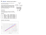
Specification
Type
Of
Input
Power
From
Welding
Power
Source
Maximum
Weld
Circuit
Rating
Welding
Power
Source
Type
Wire
Feed
Speed
Range
Description
Wire
Diameter
Range
Welding
Process
Input
Power
Cord
Single-Phase
24
Volts
AC,
10
Amperes,
50/60
Hertz.
(If
115
Volts
AC
Is
The
Only
Power
Available,
Use
Optional
Power
Supply
Adapter
Model
PSA-2.)
100
Volts,
750
Amperes,
100%
Duty
Cycle
Constant
Voltage
(CV)
DC,
With
Contactor
50 To
780
ipm
(1.3
To
19.8
mpm);
Standard
Motor
14
To
213
ipm
(0.6
To
5.4
mpm);
Low
Speed
Motor
9010
1400
ipm
(2.3
To
35.6
mpm);
High
Speed
Motor
.023
To
1/8
in
(0.6
To
3.2
mm)
Gas
Metal
Arc
(GMAW)
Or
Flux
Cored
Arc
Welding
(FCAW)
lOft(3.1
m)
Maximum
Height
With
4
ft
(1.2
m)
Post
Weight
12
ft
(3.7
m)
Boom
17ft(5.2m)
Vertical
Lift
Of
Boom
Net:
160
lb
(73
kg)
Ship:
280
lb
(127
kg)
16
ft
(4.9
m)
Boom
21
ft
(6.4
m)
Horizontal
To
60
Above
Horizontal
Net:
210
lb
(95
kg)
Ship:
350
lb
(159
kg)
Horizontal
To
60
Above
Horizontal
OM-1583
Page
1
SECTION
3-
INSTALLATION
a
WARNING
CYLINDERS
can
explode
if
damaged.
Keep
cylinders
away
from
welding
and
other
electrical
circuits.
Never
touch
cylinder
with
welding
electrode.
Always
secure
cylinder
to
running
gear,
wall,
or
other
stationary
support.
HOT
SURFACES
can
burn
skin.
Allow
gun
to
cool
before
touching.
ELECTRIC
SHOCK
can
kill.
Do
not
touch
live
electrical
parts.
Turn
Off
wire
feederand
welding
powersource,
and
disconnect
input
power
before
making
connections.
The
welding
wire,
drive
rolls,
drive
assembly,
and
all
metal
parts
touching
the
welding
wire
are
electrically
live
when
welding
or
feeding
wire
using
gun
trigger.
Have
only
qualified
persons
install
this
unit.
wfwam9.1
2/93
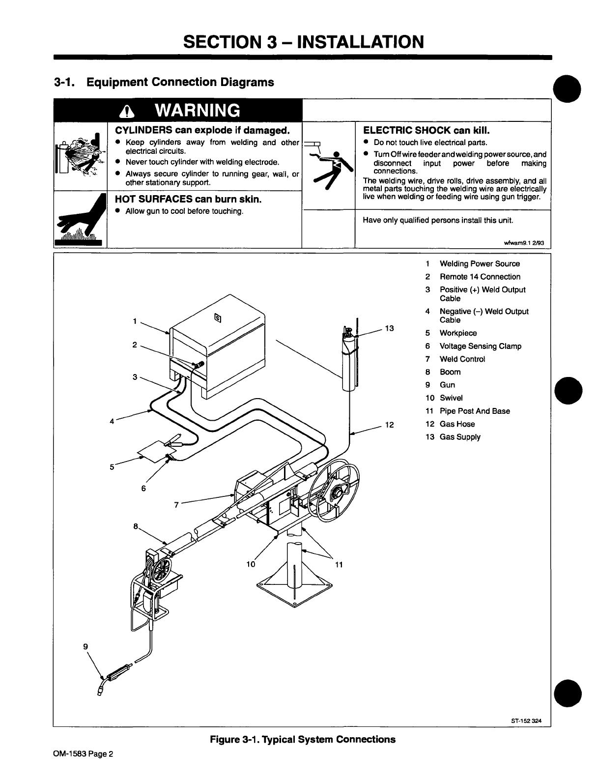
3-1.
Equipment
Connection
Diagrams
I
1
Welding
Power
Source
1
2
3
2
Remote
14
Connection
3
Positive
(+)
Weld
Output
Cable
4
Negative
()
Weld
Output
Cable
13
~
Workpiece
6
Voltage
Sensing
Clamp
7
Weld
Control
8
Boom
9
Gun
10
Swivel
11
Pipe
Post
And
Base
12
12
Gas
Hose
13
Gas
Supply
ST-i
52
324
9
Figure
3-1.
Typical
System
Connections
OM-1
583
Page
2

3-2.
Installing
Swivel
Into
Pipe
Post
a
WARNING
I.
RELEASE
OF
SPRING
PRESSURE
WITHOUT
BOOM
ATTACHED
can
cause
serious
personal
injury.
Do
not
remove
safety
collar
until
instructed
to
do
so.
FALLING
BOOM
can
cause
serious
personal
injury
and
equipment
damage.
Securely
mount
pipe
post
to
base
that
can
support
weight
of
unit
with
boom
in
horizontal
position.
Use
proper
equipment
for
lifting
swivel
and
boom
into
place.
Figure
3-2.
Swivel
Installation
1
Swivel
Plates
2
Yoke
Remove
hardware
from
swivel
plates
and
yoke.
3
Boom
Set
boom
into
swivel
as
shown.
4
Yoke
Pin
Install
pin
through
yoke.
Install
cot
ter
pin
and
spread
ends.
5
Bolt
Install
bolt,
tighten
hardware,
and
back
bolt
oft
one
half
turn.
6
Locking
Knob
Install
locking
knob
but
do
not
tighten.
7
Reel
Support
Install
reel
support.
I
5
4
3
Tools
Needed:
~
3/4in
1
Swing
pak
Base
or
CBC
Cart
2
Pipe
Post
With
Base
3
Steel
Bolt
Secure
as
shown
using
as
a
mini
mum
1/2
in
diameter
SAE
grade
5
steel
bolts.
4
Swivel
Assembly
Insert
into
pipe
post.
Lubricate
swivel.
5
Safety
Collar
Do
not
remove
until
instructed
to.
ST-152
268
3-3.
Installing
Boom
And
Reel
Support
READ
SAFETY
BLOCKS
at start
of
Section
3-2
before
proceeding.
4
7
1
2
~~0
Tools
Needed:
Z~
3/4,3/8
in
Figure
3-3.
Boom
Installation
Ref.
ST-142
596-C
OM-1583
Page
3
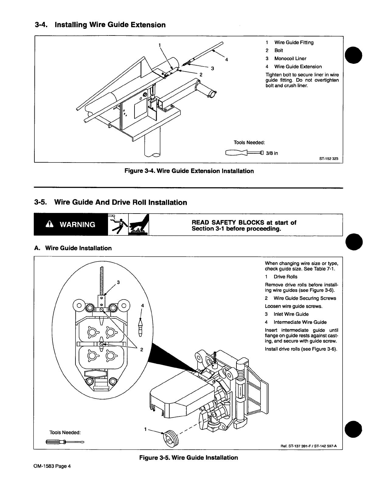
3-4.
Installing
Wire
Guide
Extension
I
~
READ
SAFETY
BLOCKS
at
start
of
Section
3-1
before
proceeding.
.
1
Wire
Guide
Fitting
2
Bolt
3
Monocoil
Liner
4
Wire
Guide
Extension
lighten
bolt
to
secure
liner
in
wire
guide
titling.
Do
not
overtighten
bolt
and
crush
liner.
Tools
Needed:
c:I:z]==i]
3/8
in
ST-i
52
323
Figure
3-4.
Wire
Guide
Extension
Installation
3-5.
Wire
Guide
And
Drive
Roll
Installation
I
A.
Wire
Guide
Installation
When
changing
wire
size
or
type,
check
guide
size.
See
Table
7-1.
1
Drive
Rolls
Remove
drive
rolls
before
install
ing
wire
guides
(see
Figure
3-6).
2
Wire
Guide
Secunng
Screws
Loosen
wire
guide
screws.
3
Inlet
Wire
Guide
4
Intermediate
Wire
Guide
Insert
intermediate
guide
until
flange
on
guide
rests
against
cast
ing,
and
secure
with
guide
screw.
~
Install
drive
rolls
(see
Figure
3-6).
Ref.
ST-137
391-F
/
ST-142
597-A
Tools
Needed:
1
Figure
3-5.
Wire
Guide
Installation
.
OM-1
583
Page
4
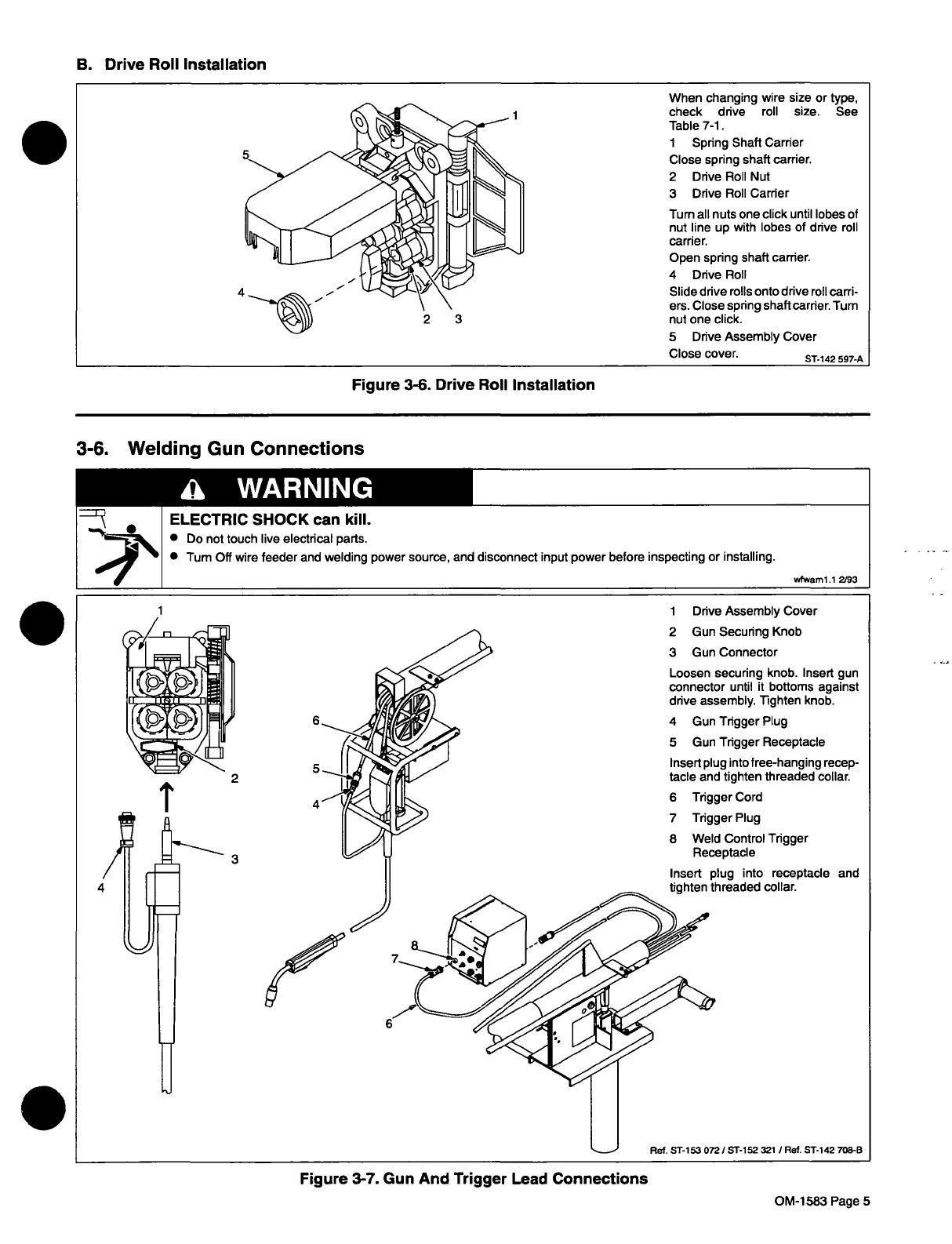
B.
Drive
Roll
Installation
Figure
3-6.
Drive
Roll
Installation
3-6.
Welding
Gun
Connections
2
3
When
changing
wire
size
or
type,
check
drive
roll
size.
See
Table
7-1.
1
Spring
Shaft
Carrier
Close
spring
shaft
carrier.
2
Drive
Roll
Nut
3
Drive
Roll
Carrier
Turn
all
nuts
one
click
until
lobes
of
nut
line
up
with
lobes
of
drive
roll
carrier.
Open
spring
shaft
carrier.
4
Drive
Roll
Slide
drive
rolls
onto
drive
roll
carri
ers.
Close
spring
shaft
carrier.
Turn
nut
one
click.
5
Drive
Assembly
Cover
Close
cover.
ST-142
597-A
£~
WARNING
ELECTRIC
SHOCK
can
kill.
~
Do
not
touch
live
electrical
parts.
Turn
Oft
wire
feeder
and
welding
power
source,
and
disconnect
input
power
before
inspecting
or
installing.
wfwaml.1
2/93
4
3
1
Drive
Assembly
Cover
2
Gun
Securing
Knob
3
Gun
Connector
Loosen
securing
knob.
Insert
gun
connector
until
it
bottoms
against
drive
assembly.
Tighten
knob.
4
Gun
Trigger
Plug
5
Gun
Trigger
Receptacle
Insert
plug
into
free-hanging
recep
tacle
and
tighten
threaded
collar.
6
Trigger
Cord
7
Trigger
Plug
8
Weld
Control
Trigger
Receptacle
Ref.
ST-153
072/
ST-152
321
/
Ref.
ST-142
708-B
Insert
tighten
plug
threa
into
receptacle
and
ded
collar.
Figure
3-7.
Gun
And
Trigger
Lead
Connections
OM-1583
Page
5
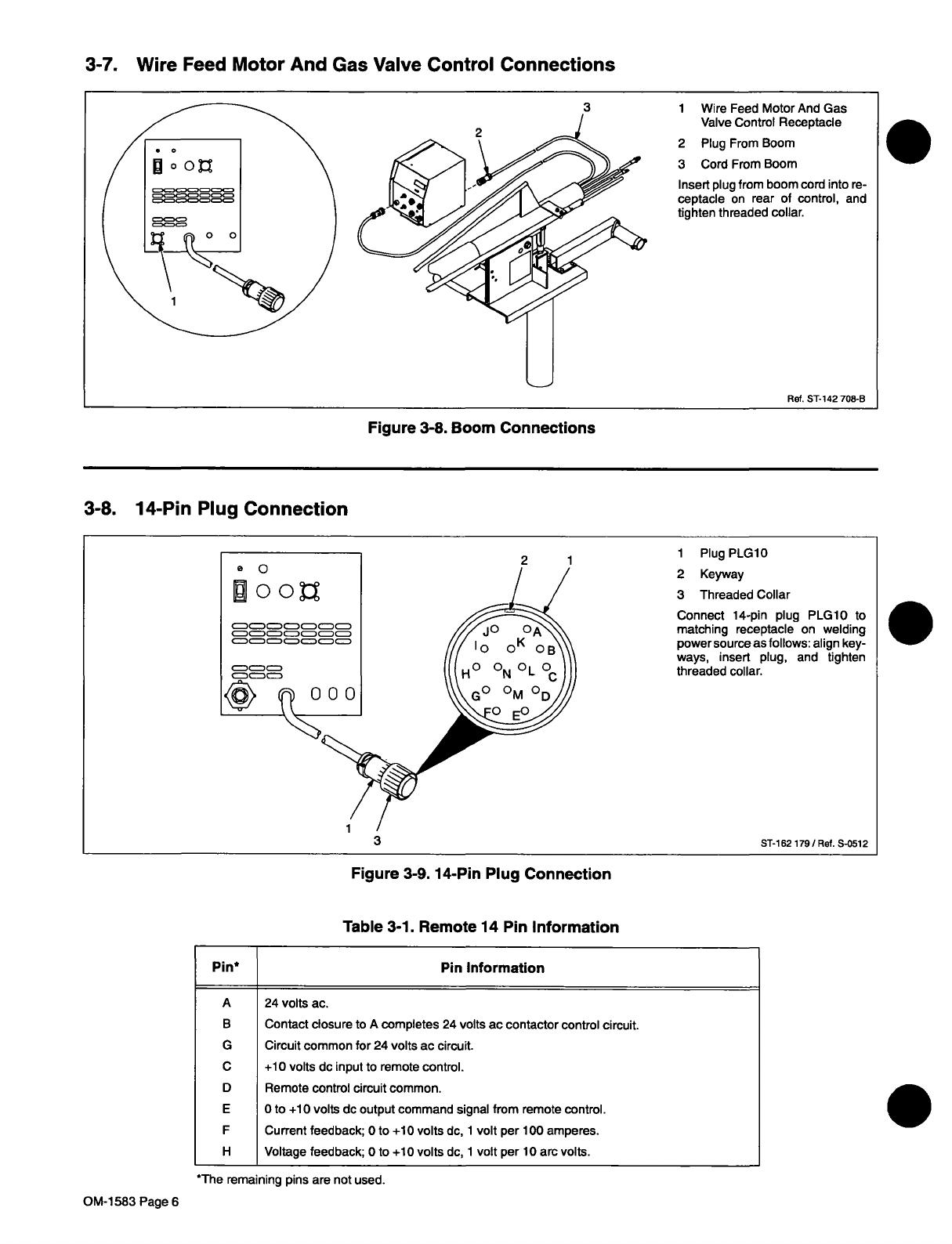
3-7.
Wire
Feed
Motor
And
Gas
Valve
Control
Connections
3-8.
14-Pin
Plug
Connection
Table
3-1.
Remote
14
Pin
Information
*The
remaining
pins
are
not
used.
1
Wire
Feed
Motor
And
Gas
Valve
Control
Receptacle
2
Plug
From
Boom
3
Cord
From
Boom
Insert
plug
from
boom
cord
into
re
ceptacle
on
rear
of
control,
and
tighten
threaded
collar.
Ref.
ST-142
708-B
Figure
3-8.
Boom
Connections
eQ
~joo~
~
2
1
1
Plug
PLG1O
2
Keyway
3
Threaded
Collar
Connect
14-pin
plug
PLG1O
to
matching
receptacle
on
welding
powersource
as
follows:
align
key
ways,
insert
plug,
and
tighten
threaded
collar.
ST-162
179/Ref.
S-0512
Figure
3-9.
14-Pin
Plug
Connection
~j~*
Pin
Information
A
24
volts
ac.
B
Contact
closure
to
A
completes
24
volts
ac
contactor
control
circuit.
G
Circuit
common
for
24
volts
ac
circuit.
C
+10
volts
dc
input
to
remote
control.
D
Remote
control
circuit
common.
E
0
to
+10
volts
dc
output
command
signal
from
remote
control.
F
Current
feedback;
Oto
+10
volts
dc,
1
volt
per
100
amperes.
H
Voltage
feedback;
0
to
+10
volts
dc,
1
volt
per
10
arc
volts.
.
OM-1
583
Page
6

3-9.
Shielding
Gas
And
Weld
Cable
Connections
£~
WARNING
CYLINDERS
can
explode
if
damaged.
Keep
cylinders
away
from
welding
and
other
electrical
circuits.
Never
touch
cylinder
with
welding
electrode.
Always
secure
cylinder
to
running
gear,
wall,
or
other
stationary
support.
ELECTRIC
SHOCK
can
kill.
Do
not
touch
live
electrical
parts.
The
welding
wire,
drive
rolls,
drive
assembly,
and
all
metal
parts
touching
the
welding
wire
are
electrically
live
when
welding
or
feeding
wire
using
gun
trigger.
BUILDUP
OF
SHIELDING
GAS
can
harm
health
or
kill.
Shut
off
shielding
gas
supply
when
not
in
use.
wam4.1
2/93
The
weld
cable
and
shielding
gas
hose
extend
10
ft
(3
m)
from
the
boom.
If
the
welding
power
source
or
gas
supply
are
further
from
the
boom,
extend
cable
or
hose
as
follows:
1
Weld
Cable
2
Insulated
Sleeving
Bolt
together
weld
cables
from
welding
power
source
and
boom.
Use
electrical
tape
and
insulated
sleeving
to
cover
connection.
3
Shielding
Gas
Hose
Connect
hose
to
gas
supply
or
ex
tension
hose.
The
hose
from
the
boom
has
5/8-18
right-hand
threads.
Tools
Needed:
~r
5/8
in
Figure
3-10.
Shielding
Gas
And
Weld
Cable
Connections
ST-152
800-A
OM-1583
Page
7
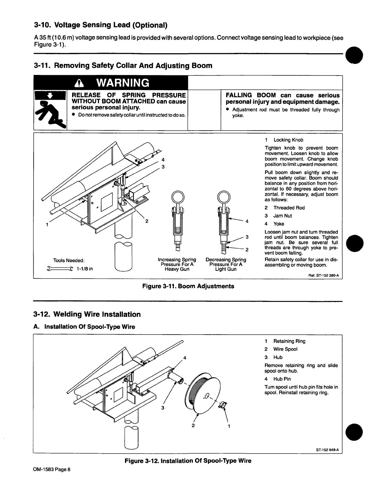
3-10.
Voltage
Sensing
Lead
(Optional)
A
35
ft
(10.6
m)
voltage
sensing
lead
is
provided
with
several
options.
Connect
voltage
sensing
lead
to
workpiece
(see
Figure
3-1).
3-11.
Removing
Safety
Collar
And
Adjusting
Boom
RELEASE
OF
SPRING
PRESSURE
FALLING
BOOM
can
cause
serious
WITHOUT
BOOM
ATTACHED
can
cause
serious
personal
ifljUflJ.
Do
not
remove
safety
collar
until
instructed
to
do
so.
personal
injury
and
equipment
damage.
Adjustment
rod
must
be
threaded
fully
through
yoke.
1
Locking
Knob
Tighten
knob
to
prevent
boom
movement.
Loosen
knob
to
allow
4
boom
movement.
Change
knob
3
position
to
limit
upward
movement.
Tools
Needed:
~~==z~
1-1/Sin
Pull
boom
down
slightly
and
re
move
safety
collar.
Boom
should
balance
in
any
position
from
hori
O
~
~
~_
I~Li~
~
3
2
Increasing
Spring
Decreasing
Spring
Pressure
For
A
Pressure
For
A
Heavy
Gun
Light
Gun
zontal
to
60
degrees
above
hori
zontal.
If
necessary,
adjust
boom
as
follows:
2
Threaded
Rod
3
Jam
Nut
4
Yoke
Loosen
jam
nut
and
tum
threaded
rod
until
boom
balances.
Tighten
jam
nut.
Be
sure
several
full
threads
are
through
yoke
to
pre
vent
boom
falling.
Retain
safety
collar
for
use
in
dis
assembling
or
moving
boom.
Ref.
ST-i
52380-A
Figure
3-11.
Boom
Adjustments
3-12.
Welding
Wire
Installation
A.
Ins
tallation
Of
Spoo
I-Type
Wire
~c
1
Retaining
Ring
2
Wire
Spool
3
Hub
Remove
retaining
ring
and
slide
spool
onto
hub.
4
Hub
Pin
Tum
spool
until
hub
pin
fits
hole
in
spool.
Reinstall
retaining
ring.
2
1
ST-152
648-A
£~
WARNING
1
Figure
3-12.
Installation
Of
Spool-Type
Wire
.
OM-1583
Page
8
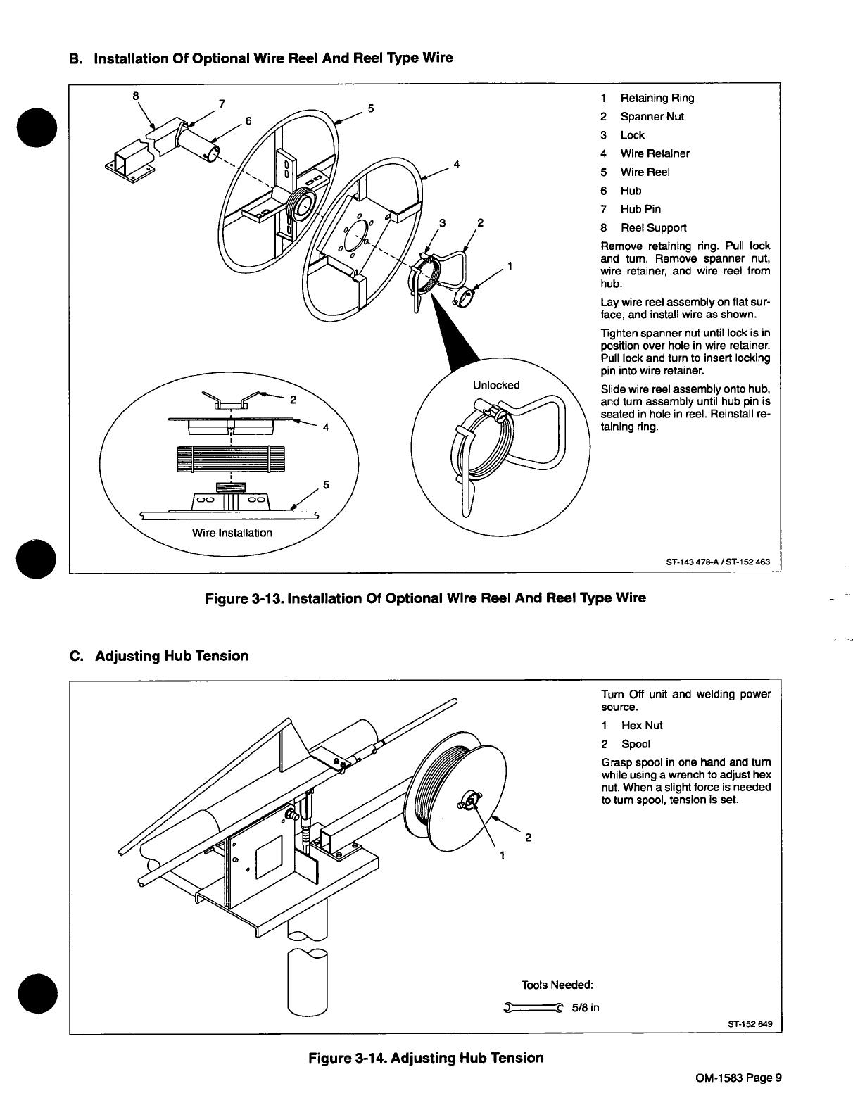
B.
Installation
Of
Optional
Wire
Reel
And
Reel
Type
Wire
C.
Adjusting
Hub
Tension
Figure
3-14.
Adjusting
Hub
Tension
7
5
4
2
1
Retaining
Ring
2
Spanner
Nut
3
Lock
4
Wire
Retainer
5
Wire
Reel
6
Hub
7
Hub
Pin
8
ReelSupport
Remove
retaining
ring.
Pull
lock
and
turn.
Remove
spanner
nut,
wire
retainer,
and
wire
reel
from
hub.
Lay
wire
reel
assembly
on
flat
sur
face,
and
install
wire
as
shown.
Tighten
spanner
nut
until
lock
is
in
position
over
hole
in
wire
retainer.
Pull
lock
and
turn
to
insert
locking
pin
into
wire
retainer.
Slide
wire
reel
assembly
onto
hub,
and
turn
assembly
until
hub
pin
is
seated
in
hole
in
reel.
Reinstall
re
taining
ring.
ST-143
478-A
I
ST-152
463
Figure
3-13.
Installation
Of
Optional
Wire
Reel
And
Reel
Type
Wire
1
Turn
Off
unit
and
welding
power
source.
1
Hex
Nut
2
Spool
Grasp
spool
in
one
hand
and
turn
while
using
a
wrench
to
adjust
hex
nut.
When
a
slight
force
is
needed
to
turn
spool,
tension
is
set.
2
E
Tools
Needed:
~
5/8
in
ST-152
649
OM-1583
Page
9

3-13.
Motor
Start
Control
£~
WARNING
ELECTRIC
SHOCK
can
kill.
Do
not
touch
live
electrical
parts.
Turn
Off
wire
feederand
welding
powersource,
and
disconnect
input
power
before
inspecting
or
installing.
STATIC
ELECTRICITY
can
damage
parts
on
circuit
boards.
Put
on
grounded
wrist
strap
BEFORE
handling
boards
or
parts.
wfwaml.1
2/93
Tools
Needed:
C111Z1U
1/4
in
~~=====~
non-conductive
Remove
wrapper.
1
Front
Panel
Remove
screw
from
upper
left
cor
ner,
and
open
hinged
front
panel.
2
Motor
Board
PCi
3
Motor
Start
Control
Poten
tiometer
R70
Turn
potentiometer
clockwise
to
in
crease
time
it
takes
the
motor
to
ramp
up
to
speed.
Remove
protec
tive
white
rubber
cap
before
making
adjustment.
Adjust
poten
tiometer
R70
using
a
small
non
conductive
screwdriver.
Figure
3-15.
Motor
Start
Control
On
Motor
Control
Board
PCi
To
change
wire
feed
starting
speed
proceed
as
follows:
Turn
Off
unit
and
welding
power
source.
Close
and
secure
front
panel,
and
reinstall
wrapper.
ST-i
52
318!
SB-146
662-D
.
OM-1
583
Page
10

3-14.
Dip
Switches
Options
AA
WARNING
ELECTRIC
SHOCK
can
kill.
Do
not
touch
live
electrical
parts.
TumOffwirefeederaridwelding
powersource,
disconnect
input
power
before
inspecting
installing.
STATIC
ELECTRICITY
can
damage
parts
on
circuit
boards.
Put
on
grounded
wrist
strap
BEFORE
handling
boards
or
parts.
wfwaml.1*
2/93
ci~zj===~n
1/4
in
Figure
3-16.
Spot
Time
DIP
Switch
Si
SA-146
866-B
/
Ref.
SB-152
378
A.
Spot
Time
DIP
Switch
Si
Change
DIP
switch
position
if
a
different
range
of
Spot
Time
is
desired.
Turn
Off
wire
feeder
and
welding
power
source.
Remove
wrapper.
1
Front
Panel
Remove
screw
from
upper
left
cor
ner,
and
open
hinged
front
panel.
2
4-In-i
Board
PC3O
3
Spot
Time
DIP
Switch
Si
Place
switch
in
desired
position:
Long
Time
for
0-5
seconds,
and
Short
Time
for
0-2.5
seconds
(see
Figure
4-12
for
control
operation).
Close
and
secure
front
panel,
and
reinstall
wrapper.
Tools
Needed:
OM-i
583
Page
ii

B.
Digital
Meter
Functions
And
Positions
NOTE
~
The
Digital
Meter
Board
PC6O
for
the
Two
Meter
Option
is
equipped
with
DIP
____________________
switch
S3.
This
switch
is
shipped
from
the
factoiyin
the
Off
position,
and
shouldnot
be
changed.
Tools
Needed:
cII~ZI===u
1/4
in
2
3
X
Means
switch
can
be
in
either
position.
I
Means
place
switch
in
this
position.
Change
DIP
switch
positions
if
a
different
mode
of
operation
is
desired.
Turn
Off
wire
feeder
and
welding
power
source.
Remove
the
three
(3)
screws
from
front
edge
of
wrapper.
1
Front
Panel
Remove
screw
from
upper
left
cor
ner,
and
open
hinged
front
panel.
2
Digital
Meter
Board
PC6O
3
Meter
Functions
DIP
Switch
S2
Place
DIP
switch
in
appropriate
po
sition
for
desired
mode
(see
Figure
4-7
for
meter
operation).
Close
and
secure
front
panel,
and
reinstall
wrapper
screws.
SB-137
395-B
/
SA-148
666-E/
S-0389
A
Figure
3-17.
Digital
Meter
Functions
DIP
Switch
S2
Standard
Motor
Inches/Minute
I
I
I
I
-,
Standard
Motor
Meters/Minute
I
I,
IC
IC
Or
High
Speed
Motor
Inches/Minute
.~
I~
.c~1
High
Speed
Motor
Meters/Minute
I
I~
IV)
Or
OM-1
583
Page
12
Page is loading ...
Page is loading ...
Page is loading ...
Page is loading ...
Page is loading ...
Page is loading ...
Page is loading ...
Page is loading ...
Page is loading ...
Page is loading ...
Page is loading ...
Page is loading ...
Page is loading ...
Page is loading ...
Page is loading ...
Page is loading ...
Page is loading ...
Page is loading ...
Page is loading ...
Page is loading ...
Page is loading ...
Page is loading ...
Page is loading ...
Page is loading ...
Page is loading ...
Page is loading ...
Page is loading ...
Page is loading ...
Page is loading ...
Page is loading ...
Page is loading ...
Page is loading ...
Page is loading ...
Page is loading ...
Page is loading ...
Page is loading ...
/