Page is loading ...

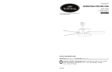
EASTVIEW CEILING FAN
ITEM #0331091
MODEL #LP8074LAZ
Questions, problems, missing parts? Before returning to your retailer, call our customer service
department at 1-888-567-2055, 8 a.m. - 5 p.m., EST, Monday - Friday.
Friday.
Español p. 20
Serial Number
Purchase Date
ATTACH YOUR RECEIPT HERE
welcoming • sophisticated • inspiring
allen + roth
®
is a registered trademark
of LF, LLC. All Rights Reserved.
EB13240
Lowes.com/allenandroth
1

Lowes.com/allenandroth
TABLE OF CONTENTS
Package Contents .........................................................................................................................
Hardware Contents .......................................................................................................................
Safety Information .........................................................................................................................
Preparation ...................................................................................................................................
Assembly Instructions ...................................................................................................................
Wiring Instructions ........................................................................................................................
Final Assembly Instructions ..........................................................................................................
Operating Instructions ...................................................................................................................
Care and Maintenance .................................................................................................................
Troubleshooting ............................................................................................................................
Warranty .......................................................................................................................................
Replacement Parts List ................................................................................................................
3
4
4
5
6
11
13
14
16
16
18
19
2

PACKAGE CONTENTS
YTITNAUQ NOITPIRCSED TRAP
Lowes.com/allenandroth
A D H
IE
F
G
B
C
A
B
C
D
E
F
G
H
I
Motor Assembly
Hanger Bracket
Downrod
Ceiling Canopy
Canopy Screw Cover
Motor Coupling Cover
Receiver Unit
Remote
Bulb
1
1
1
1
1
1
1
1
4
3

and can radiate radio frequency energy and, if not installed and used in accordance with the
instructions, may cause harmful interference to radio or television reception, which can be
determined by turning the equipment off and on, the user is encouraged to try to correct the
interference by one or more of the following measures:
Wire
Connector
Qty. 4
AA
HARDWARE CONTENTS (shown actual size)
Lowes.com/allenandroth
SAFETY INFORMATION
Please read and understand this entire manual before attempting to assemble, operate or install
the product.
• Before you begin installing the fan, disconnect the power by removing fuses or turning off circuit
breakers.
• Make sure all electrical connections comply with local codes, ordinances, or the National
Electrical code. Hire a qualified electrician or consult a do-it-yourself wiring handbook if you are
unfamiliar with installing electrical wiring.
• Make sure the installation site you choose allows a minimum clearance of 7 ft. from the blades
to the floor and at least 30 in. from the ends of the blades to any obstruction.
• If you are mounting the fan to a ceiling outlet box, use a METAL octagonal outlet box.
Secure the box directly to the building structure. The outlet box and its support must be able to
support the moving weight of the fan (at least 35 lbs.). Do NOT use a plastic outlet box.
• After you install the fan, make sure all connections are secure to prevent the fan from falling.
• For supply connections, if the conductor of a fan is identified as a grounded conductor, then it
should be connected to a grounded conductor power supply. If the conductor of a fan is identified
as an ungrounded conductor, then it should be connected to an ungrounded conductor power
supply. If the conductor of a fan is identified for equipment grounding, then it should be connected
to an equipment-grounding conductor.
• This device complies with Part 15 of the FCC Rules. Operation is subject to the following two
conditions: (1) This device may not cause harmful interference, and (2) this device must accept
any interference received, including interference that may cause undesired operation.
If the intentional radiator can be classified as a Class B digital device or a PC peripheral, then shall
include the following or equivalent:
Note: This equipment has been tested and found to comply with the limits for Class B digital
device, pursuant to part 15 of the FCC Rules. These limits are designed to provide reasonable
protection against harmful interference in a residential installation. This equipment generates, uses
4
- Reorient or relocate the receiving antenna.
- Increase the separation between the equipment and the receiver.
- Connect the equipment into an outlet on a circuit different from that to which the receiver is
connected.

Lowes.com/allenandroth
SAFETY INFORMATION
•The net weight of this fan is: 26.01 lbs.
Consult the dealer or an experienced radio/TV technician for help.
Note: For a Class A digital device, statements of 15. 105(a) must be included when appropriate
forthe device in question.
Before beginning assembly of product, make sure all parts are present. Compare parts with
package contents list and hardware contents list. If any part is missing or damaged, do not
attempt to assemble the product.
Estimated Assembly Time: 60 minutes
Tools Required for Assembly (not included): Phillips screwdriver, 1/4 in. flathead screwdriver,
wire stripper and step ladder.
Helpful Tools (not included): AC tester light, do-it-yourself wiring handbook and wire cutters.
PREPARATION
WARNING
• Do not install or use fan if any part is damaged or missing.
• To reduce the risk of fire, electrical shock, or personal injury, wire connectors provided with this
fan are designed to accept only one 12-gauge house wire and two lead wires from the fan. If
your house wire is larger than 12-gauge or there is more than one house wire to connect to the
two fan lead wires, consult an electrician for the proper size wire connectors to use. Before
cutting, drilling or hammering, verify their location. If needed, contact your electrician, plumber
or service person.
• To reduce the risk of fire, electric shock, or personal injur
• To reduce the risk of electric shock, disconnect the electrical supply circuit to the fan before
installing light kit.
• To reduce the risk of fire or electric shock, do not use this fan with any solid-state speed control device.
y, do not bend the blade arms when
installing them, balancing the blades, or cleaning the fan. Do not insert foreign objects between
the rotating fan blades. Mount to outlet box marked “ACCEPTABLE FOR FAN SUPPORT” and
use mounting screws provided with the outlet box. Most outlet boxes commonly used for the
support of lighting fixtures are not acceptable for fan support and may need to be replaced.
Consult a qualified electrician if in doubt.
• Use this unit only in the manner intended by the manufacturer. If you have question, contact the
manufacturer.
• This fan is to be used in dry locations onl
• The splices after being made should be turned upward and pushed carefully up into the outlet box.
• A diagram showing the fan, intended mounting means and ceiling outlet box with fan canopy covering
the outlet box.
• After making the wire connections, the wires should be spread apart with the grounded conductor and
the equipment-grounding conductor on one side of the outlet box and the ungrounded conductor on
the other side of the outlet box.
y.
• Read all instructions and safety information before installing the new fan. Review accompanying
assembly diagrams.
CAUTION
5
• Do not operate this fan with a variable (Rheostat) wall controller or dimmer switch. Doing so could
result in damage to the ceiling fan's remote control unit.

C
Lowes.com/allenandroth
ASSEMBLY INSTRUCTIONS
1
C
2
1. Remove the hanger ball portion from the
downrod (C) by loosening the preassembled
set screw in the hanger ball until the ball falls
freely down the downrod (C). Remove the
preassembled pin from the downrod (C), then
remove the hanger ball. Retain the pin and
hanger ball for later.
2. Remove the preassembled hairpin clip and
clevis pin from the bottom of downrod (C).
Retain the pin and clip for later.
C
A
3
3. Loosen the two preassembled set screws in
the downrod support of the motor assembly
(A). Route the black, white and blue wires
through the downrod (C).
6

Lowes.com/allenandroth
ASSEMBLY INSTRUCTIONS
4
C
A
4. Thread the downrod (C) into downrod support
of the motor assembly (A). Align the holes in
the downrod support of the motor assembly (A)
with the holes in the downrod (C) and install the
previously removed clevis pin. Secure clevis
pin with previously removed hairpin clip.
Tighten the two set screws in the downrod
support of the motor assembly (A).
WARNING
It is critical the clevis pin in the downrod support
is properly installed and the set screws are
securely tightened. Failure to do so could result
in the fan falling.
5. Route wires through motor coupling cover
(F), canopy screw cover (E) and ceiling
canopy (D).
Note: The keyslots of the canopy screw cover (E)
should be toward the ceiling direction.
6. Reinstall the hanger ball on the downrod (C)
by routing the three 54 in. wires from the motor
assembly (A) through the hanger ball. Position
the pin removed in step 1 through the two
holes in the downrod (C) and align the hanger
ball so the pin is captured in the groove in the
top of the hanger ball. Pull the hanger ball up
tight against the pin. Securely tighten the
preassembled set screw in the hanger ball.
A loose set screw could result in a wobbly fan.
CAUTION
C
6
7
5
E
D
F

I
9
9. Install bulbs (I).
8. Remove the preassembled screws and take
off the 4 light caps in the motor assembly (A).
Retain the screws and light caps for later.
8
A
Lowes.com/allenandroth
ASSEMBLY INSTRUCTIONS
C
6
t
o
9
in
.
7
7. Cut off excess lead wire approximately 6 to 9
in. above top of the top of the downrod (C).
Strip insulation off 1/2 in. from the end of each
lead wire.
8

10. Put the light caps back and securely tighten
the previously removed screws of light caps.
10
NOTE: If you are not sure if the outlet box is
grounded, contact a licensed electrician for
advice, as it must be grounded for safe operation.
WARNING
To avoid possible electrical shock, be sure
electricity is turned off at the main fuse box before
hanging.
WARNING
The fan must hang with at least 7 ft. of clearance
from the floor to blades.
B
11
11. Securely attach the hanger bracket (B) to the
outlet box (not included) using the outlet box
screws and washers supplied with the outlet
box.
WARNING
The outlet box must be securely anchored.
Hanger bracket must seat firmly against outlet
box. If the outlet box is recessed, remove
wallboard until bracket contacts box. If bracket
and/or outlet box are not securely attached, the
fan could wobble or fall.
Lowes.com/allenandroth
ASSEMBLY INSTRUCTIONS
9

Lowes.com/allenandroth
ASSEMBLY INSTRUCTIONS
B
C
12
12. Carefully lift the assembly and seat hanger .
ball of the downrod (C) on the hanger bracket
(B). Be sure the groove in the ball is lined up
with tab on the hanger bracket (B).
WARNING
Failure to seat tab in groove could cause damage
to electrical wires and possible shock or fire
hazard.
To avoid possible shock, do not pinch wires
between the hanger ball assembly and the
hanger bracket.
10

Lowes.com/allenandroth
WIRING INSTRUCTIONS
NOTE: If you are not sure if the outlet box is grounded, contact a licensed electrician for advice, as it
must be grounded for safe operation.
NOTE: Remote (H) has 16 different code combinations. To prevent possible interference from or to
other remote units, simply change the combination code in the transmitter and receiver.
1. To set the transmitter code, remove battery
cover on remote (H) by pressing firmly below
arrow and sliding cover off. Slide code
switches to your choice of up or down position.
Factory setting is all up. Do not use this
position. With a small screwdriver or ball point
pen (not included), slide firmly up or down.
Replace battery cover on remote (H).
H
12V
Battery
1
WARNING
To avoid possible electrical shock, be sure electricity is turned off at the main fuse box before wiring
this fan.
2. To set the receiver unit (G) code, slide code
switches to the same positions as set on
remote (H).
G
2
11

Lowes.com/allenandroth
WIRING INSTRUCTIONS
G
B
3. Slide the receiver unit (G) into the open end of
the hanger bracket (B).
3
Hardware Used
x 3
Wire
Connector
AA
AA
AA
AA
4
Blue to Light
Black to Motor
White to Motor
all
G
C
B
WARNING
Check to see all connections are tight,
including ground, and no bare wire is visible
at the wire connectors except for the ground
wire. Do not operate fan until the blades are in
place. Noise and motor damage could result.
4. Connect green wires from hanger bracket (B)
and downrod (C) to bare (ground) wire using wire
connector (AA). Connect black wire from
receiver unit (G) marked “AC IN L” to black
supply wire using wire connector (AA). Connect
white wire from rece
iver unit (G) marked “AC IN
N” to white supply wire using wire connector
(AA). Connect white wire from receiver unit (G)
marked “TO MOTOR N” to white wire from fan
using wire connector supplied with receiver unit
(G). Connect black wire from receiver unit (G)
marked “TO MOTOR L” to black wire from fan
using wire connector supplied with receiver unit
(G). Lastly, connect blue wire from re
ceiver uni
t
(G) to the blue fan light wire using wire connector
supplied with receiver unit (G).
12

FINAL ASSEMBLY INSTRUCTIONS
1
D
2
E
1. Remove one of the two preassembled
shoulder screws in the hanger bracket (B).
Loosen the second shoulder screw without
fully removing it. Rotate ceiling canopy (D) so
second shoulder screw moves into the small
opening of the keyslot. Tighten shoulder
screw. Re-install the previously removed
shoulder screw to fully assemble ceiling
canopy (D) to hanger bracket (B).
2. Securely attach and tighten the canopy
screw cover (E) over the shoulder screws in
the hanger bracket (B), utilizing the keyslot
twist-lock feature.
WARNING
To avoid possible fire or shock, make sure the
electrical wires are completely inside the canopy
housing and not pinched between the housing
and the ceiling.
Lowes.com/allenandroth
5. After connections have been made, turn leads
upward and carefully push power supply wire
leads into the outlet box, with the white and
green leads to one side of the box and the
black leads toward the other side.
5
all
WIRING INSTRUCTIONS
13

OPERATING INSTRUCTIONS
2
1. Restore electrical power to the outlet box by
turning the electricity on at the main fuse box.
1
ON
ON
ON
ON
ON
ON
ON
ON
14
3
H
3. To make fan operational, install 12-volt battery
(included in remote control package) into the
remote (H).
WARNING
Nor-rechargeable batteries are not to be recharged
batteries are to be inserted with the correct polarity.
Exhausted batteries are to be removed from the
product " DO NOT DISPOSE OF BATTERIES IN
FIRE. BATTERIES MAY EXPLODE OR LEAK".
or the equivalent.
Note: When it is time to replace battery, use a
12-volt alkaline battery.
2.
IMPORTANT: Using a full range dimmer switch
(not included) to control fan speed will damage
the fan. To reduce the risk of fire or electrical shock,
do not use a full range dimmer switch to control the
fan speed.
For illustrative purposes only-not
intended to cover all types of controls
WARNING
Do not operate this fan with a variable (Rheostat)
wall controller or dimmer switch. Doing so could
result in damage to the ceiling fan's remote
control unit.

4
H
4. The remote (H) includes buttons for high,
medium and low fan speeds as well as fan
OFF and light ON/OFF. Varying light levels are
available by holding down the light ON/OFF
button.
If you are not expecting to use the remote for a
long period of time, remove the battery to
prevent damage to the remote. Be sure to store
the remote away from excess heat or humidity.
CAUTION
Lowes.com/allenandroth
OPERATING INSTRUCTIONS
15
Reverse Switch Information
Season Rotation Direction Switch Position
Summer Counter-Clockwise
Left
Winter Clockwise
Right
5. If airflow is desired in the opposite direction,
turn the fan off and wait for the blades to stop
turning. Slide the reverse switch on top of motor
assembly to the opposite position and turn fan
on again.
5

Lowes.com/allenandroth
• When cleaning, use only a soft brush or lint-free cloth to avoid scratching the finish.
• Abrasive cleaning agents are not required and should be avoided to prevent damage to finish.
RECOMMENDED: Periodically check that the fan motor unit screws, blade screws, support
housing and light kit screws are tight and secure.
• Periodic light dusting of the blades is recommended. A feather duster will work best.
• Avoid using water, cleansers, or harsh rags, which can warp and ruin the finish.
• Bulb Replacement: Use 40-watt candelabra-base bulbs.
CARE AND MAINTENANCE
WARNING
• Do not use water when cleaning the ceiling fan. It could damage the motor or the finish and
create the possibility of electrical shock.
• Re-lamp with the appropriate wattage bulb. Do not exceed the wattage indicated on the bulb
socket.
• Do not install or use fan if any part is damaged or missing.
TROUBLESHOOTING
4. Wire connectors inside housing are
rattling.
1. Blades not attached to fan.
2. Loose screws in motor housing.
3. Screws securing fan blade holders to
motor hub are loose.
1. Check main and branch circuit
fuses or circuit breakers.
2. Check line wire connections to
fan.
WARNING
Make sure main power is turned
off!
4. Check to make sure wire
connectors in switch housing
are not rattling against each
other or against the interior wall
of the switch housing.
1. Attach blades to fan before
operating.
2. Check to make sure all screws
in motor housing are snug
(do not overtighten).
3. Check to make sure the screws
that attach the fan blade
holders to the motor hub are tight.
PROBLEM POSSIBLE CAUSE CORRECTIVE ACTION
Fan will not start. 1. Fuse or circuit breaker blown.
2. Loose power line connections
3. Dead battery in remote control. 3. Replace with new battery.
to the fan.
Fan sounds noisy.
16

Lowes.com/allenandroth
CARE AND MAINTENANCE
6. Screws holding blades to blade
holders are loose.
6. Tighten screws securely.
Fan sounds noisy.
Not enough air
movement.
6. Fan blades are out of balance.
1. Set screw in downrod support is loose.
2. Set screw in downrod/hanger ball
assembly is loose.
3. Screws securing fan blade holders to
motor hub are loose.
4. Blade holders are not seated properly.
5. Hanger bracket and/or ceiling outlet box
is not securely fastened.
If possible, consider using a longer
downrod (not included).
6. Interchanging position of fan
blades can redistribute the
weight and result in a smoother
operation. For example,
exchange blades in positions 1
and 3 or 1 and 4. If this does
not improve wobble, exchange
2 and 4 or 2 and 5.
2. Tighten the set screw in the
downrod/hanger ball assembly.
3. Check to be sure screws that
attach the fan blade holders to the
motor hub are tight.
4. Check to be sure the fan blade
holders seat firmly and
uniformly to the surface of the
motor housing. If holders are
seated incorrectly, loosen the
screws and retighten.
5. Tighten the hanger bracket
screws to the outlet box, and
secure outlet box.
1. Tighten set screws securely in
downrod support.
Downrod is too short.
PROBLEM POSSIBLE CAUSE CORRECTIVE ACTION
Fan wobbles
excessively.
5. Motor noise caused by solid state
variable speed control.
5. Some fan motors are sensitive
to signals from solid-state
variable speed controls.
Solid-state controls are not
recommended, choose an
alternative control method.
17

WARRANTY
To obtain warranty service, present a copy of your sales receipt as proof of purchase. All cost of
removal and reinstallation are the expressed responsibility of the purchaser. Any damage to the
ceiling fan by accident, misuse or improper installation, or by affixing accessories not produced by
this warranty, are at the purchaser’s own responsibility. The manufacturer assumes no responsibility
whatsoever for fan installation during the lifetime limited warranty. Any service performed by an
unauthorized person will render the warranty invalid.
Due to varying climate conditions, this warranty does not cover changes in brass finish, rusting,
pitting, tarnishing, corroding or peeling. Brass finish fans maintain their beauty when protected from
varying weather conditions. Any glass provided with this fan is not covered by the warranty.
Any replacement of defective parts for the ceiling fan must be reported within the first year from the
date of purchase. For the balance of the warranty, call our customer service department at
1-888-567-2055 for return authorization and shipping instructions so that we may repair or replace
the ceiling fan. Any fan or parts returned improperly packaged is the sole responsibility of the purchaser.
There is no further expressed warranty. The manufacturer disclaims any and all implied warranties.
The duration of any implied warranty which can not be disclaimed is limited to the lifetime limited
period as specified in our warranty. The manufacturer shall not be liable for incidental, consequential
or special damages arising at or in connection with product use or performance except as may
otherwise be accorded by law. This warranty gives you specific legal rights and you also have other
rights which vary from state to state. This warranty supersedes all prior warranties.
Note: A small amount of “wobble” is normal and should not be considered a defect.
Lowes.com/allenandroth
The manufacturer warrants this fan to be free from defects in workmanship and material present at
time of shipment from the factory. The warranty terms from the date of purchase. The motor has a
lifetime warranty, and a 2 year warranty for the light kit and all remaining components. This warranty
applies only to the original purchaser. The manufacturer agrees to correct such defect at no charge
or, at our option, replace the ceiling fan with a comparable or superior model.
18

AA
B
C
D
A
I
H
G
E
F
L
REPLACEMENT PARTS LIST
For replacement parts, call our customer service department at 1-888-567-2055, 8 a.m. - 5 p.m.,
EST, Monday - Friday.
Printed in China
allen + roth
®
is a registered trademark
of LF, LLC. All rights reserved.
Lowes.com/allenandroth
# TRAP NOITPIRCSED TRAP
Motor Assembly
Hanger Bracket
Downrod
Ceiling Canopy
Canopy Screw Cover
Motor Coupling Cover
Receiver Unit
Remote
Bulb
Wire Connector
AMA8074LAZ
APGAC110RBL
ADRACT1-45LAZ
P807421LAZ
APPAC1101LAZ
AP1115LAZ
RECAN26
TR350AR
PPE12B40
HDWWNUTS4
A
B
C
D
E
F
G
H
I
AA
19

ARTÍCULO #0331091
MODELO #LP8074LAZ
VENTILADOR DE TECHO EASTVIEW
Número de serie
Fecha de compra
ADJUNTAR SU RECIBO AQUÍ
allen + roth
®
es una marca registrada
de LF, LLC. Todos los derechos reservados.
Lowes.com/allenandroth
¿Preguntas, problemas, piezas faltantes? Antes de volver a la tienda, llame a nuestro
Departamento de Servicio al Cliente al 1-888-567-2055, 8 a.m. - 5 pm, hora del Este, de lunes -
viernes.
20
welcoming • sophisticated • inspiring
/