Tripp Lite On-Line Tower LCD UPS User manual

Category
Uninterruptible power supplies (UPSs)
Type
User manual

This manual is also suitable for

SU1000XLCD SU1500XLCD
SU2200XLCD
SU3000XLCD
1
Owner’s Manual
SmartOnline
Single-Phase Tower Online UPS Systems
with Built-in LCD Monitoring & Control Screen
Not suitable for mobile applications.
1111 W. 35th Street, Chicago, IL 60609 USA www.tripplite.com/support
Copyright ©2013 Tripp Lite. All rights reserved. SmartOnline™ is a trademark of Tripp Lite. For latest updates, please visit www.tripplite.com
1. Overview 2
Parts List 2
Additional Accessory Options 2
Model Specific Accessories 2
2. Important Safety Instructions 3
3. Features 4
Front Panel Control Buttons & LCD 4
Rear Panel Features 9
4. Basic Connection and Start-Up 11
Quick Start Guide 11
Optional Connections 13
5. Operation 16
Modes of Operation 16
LCD Status & Supported Measurements 20
UPS Setup Overview 21
Using The LCD Interface 21
Using PowerAlert Power Management Software 25
6. Troubleshooting 26
7. Internal Battery Replacement 26
8. Storage and Service 30
9. Warranty Registration 31
Español 33
Français 65
Warranty
Registration:
register online today for a
chance to win a FREE Tripp Lite
product—www.tripplite.com/warranty
Quick Start
Guide—
Page 11
NOTE: External battery pack options require configuration using the front panel LCD interface or via Tripp Lite’s EXTERNAL BATTERY CONFIGURATION software. See page 24 for
more information if you are connecting external batteries to one of these UPS models.
13-03-138 93-3168-EN.indd 1 3/28/2013 1:04:18 PM
2
Overview
Tripp Lite SmartOnline tower UPS Systems with interactive LCD interface feature online, double-conversion UPS protection with full-time
sine wave output and zero transfer time suitable for all advanced networking applications. Each system provides long running battery
support with optional extended-run and SNMP/Web communications ability. Built-in interfaces include USB, DB9 serial and Emergency
Power Off (EPO). The interactive front panel LCD screen provides detailed UPS status, preset and control options. An optional economy
mode setting reduces power consumption and BTU heat output.
Parts List
UPS System PowerAlert CD USB Cable EPO (RJ11) Cable
RS-232 Cable Owner’s manual
Additional Accessories (All Models; Optional)
•SNMPWEBCARD:InternalnetworkinterfacecardforSNMP/Webcontrolandmonitoring
•ENVIROSENSE:Temperature/HumiditysensorforusewithSNMPWEBCARD
•SRSWITCH:DoorsensorforusewithENVIROSENSEandSNMPWEBCARD
•RELAYIOCARD:ProgrammableRelayI/OCardforremoteUPSmonitoring
Model Specific Accessories (Optional)*
UPS Model SU1000XLCD SU1500XLCD SU2200XLCD SU3000XLCD
External Battery Packs
(LIMIT 1)
BP24V15RT2Uor
BP24V28-2U
BP48V24-2U BP48V24-2U BP72V15-2U
External Battery Packs
(NO LIMIT)
BP24V70RT3U BP48V60RT3U BP48V60RT3U BP72V28RT3U
Hot-swapPDUSystem PDUB15 PDUB15 PDUB20 PDUB30
3-YearExtendedWarranty WEXT3-500-1500 WEXT3-500-1500 WEXT3-2200-3000 WEXT3-2200-3000
5-YearExtendedWarranty WEXT5-500-1500 WEXT5-500-1500 WEXT5-2200-3000 WEXT5-2200-3000
*VisitthespecificationpageforyourUPSsystematwww.tripplite.comfordetailedextendedruntimedataandadditionalaccessoryoptions.
Model SU1000XLCD SU1500XLCD SU2200XLCD SU3000XLCD
UPS Dimensions
(HxWxDin.)
10x6.8x13.2 10.2 x 9 x 19.5 10.2 x 9 x 19.5 10.2 x 9 x 19.5
UPS Dimensions
(HxWxDcm.)
25.4 x 17.1 x 33.7 26.0x22.9x49.5 26.0x22.9x49.5 26.0x22.9x49.5
OperatingAltitude:0to3000m(0to10,000ft.)
13-03-138 93-3168-EN.indd 2 3/28/2013 1:04:29 PM
3
Important Safety Instructions
SAVE THESE INSTRUCTIONS
This manual contains instructions and warnings that should be followed during the installation, operation and storage of all Tripp Lite
UPS Systems. Failure to heed these warnings may affect your warranty.
UPS Location Warnings
•InstallyourUPSindoors,awayfromexcessmoistureorheat,conductivecontaminants,dustordirectsunlight.
•Forbestperformance,keeptheindoortemperaturebetween32ºFand104ºF(0ºCand40ºC).
•LeaveadequatespacearoundallsidesoftheUPSforproperventilation.
Do not install unit with its front or rear panel facing down (at any angle). Mounting in this manner will seriously inhibit the
unit’s internal cooling, eventually causing product damage not covered under warranty.
UPS Connection Warnings
•ConnectyourUPSdirectlytoaproperlygroundedACpoweroutlet.DonotplugtheUPSintoitself;thiswilldamagetheUPS.
•DonotmodifytheUPS'splug,anddonotuseanadapterthatwouldeliminatetheUPS’sgroundconnection.
•DonotuseextensioncordstoconnecttheUPStoanACoutlet.
•IftheUPSreceivespowerfromamotor-poweredACgenerator,thegeneratormustprovideclean,filtered,computer-gradeoutput.
•ThemainssocketoutletthatsuppliestheUPSshouldbeneartheUPSandbeeasilyaccessible.
•ToremoveACvoltagefromtheUPS,pulltheplugfromthesocketoutlet.
Equipment Connection Warnings
•Useofthisequipmentinlifesupportapplicationswherefailureofthisequipmentcanreasonablybeexpectedtocausethefailureofthe
lifesupportequipmentortosignificantlyaffectitssafetyoreffectivenessisnotrecommended.Donotusethisequipmentinthepresence
of a flammable anesthetic mixture with air, oxygen or nitrous oxide.
•DonotconnectsurgesuppressorsorextensioncordstotheoutputofyourUPS.ThismightdamagetheUPSandmayaffectthesurge
suppressor and UPS warranties.
•ConnecttheUPStoanoutletthatisadequatelyprotectedagainstexcesscurrents,shortcircuitsandearthfaults,aspartofthebuilding
installation. The outlet protection for the UPS should be in series with the mains input.
Battery Warnings
•Batteriescanpresentariskofelectricalshockandburnfromhighshort-circuitcurrent.Observeproperprecautions.Donotdisposeof
the batteries in a fire. Do not open the UPS or batteries. Do not short or bridge the battery terminals with any object. Unplug and turn
off the UPS before performing battery replacement. Use tools with insulated handles. There are no user-serviceable parts inside the UPS.
Battery replacement should be performed only by authorized service personnel using the same number and type of batteries (Sealed
Lead-Acid).Thebatteriesarerecyclable.Refertoyourlocalcodesfordisposalrequirementsorvisitwww.tripplite.com/UPSbatteryrecycling
forrecyclinginformation.TrippLiteoffersacompletelineofUPSSystemReplacementBatteryCartridges(R.B.C.).VisitTrippLiteonthe
Web at www.tripplite.com/support/battery/index.cfm to locate the specific replacement battery for your UPS.
Overview
EXTERNAL BATTERY CONFIGURATION NOTE
If external battery packs are to be used with this UPS, install them following the mounting/installation documentation included with each
batterypack.ExternalbatterypackinstallationrequirestheUPSbeconfiguredoneoftwoways:
1.ViatheUPSfrontpanelLCDinterface(limitedtotwoexternalBPconfigurations)
2.ViaTrippLite’sEXTERNALBATTERYCONFIGURATIONsoftware.Downloadablefromhttp://www.tripplite.com/bpconfig(forallexternal
runtime configurations)
This UPS is factory programmed with discharge curves and charging profiles for two basic external battery pack configurations accessible
using the UPS front panel LCD interface. Additional battery pack options using larger or multiple external battery packs are also supported,
but require configuration using Tripp Lite’s EXTERNAL BATTERY CONFIGURATION software and a serial port connection to the UPS.
See page 24 to determine which method applies to your external battery pack configuration.
13-03-138 93-3168-EN.indd 3 3/28/2013 1:04:30 PM
2 314
4
Features
Before installing and operating your UPS, familiarize yourself with the locations and function of the features of each component.
Front Panel Control Buttons and LCD Screen
1
LCD Informational Screens: This UPS is configured with an informative LCD screen to offer detailed UPS status, control and configuration
options. The LCD screen consists of various icons, plus a large three character display to report UPS and site power related conditions.
Indicator and Status Icons
5 BAR BATTERY CHARGE INDICATOR continuously reports battery charge level in all operating modes.
INPUT AC INDICATOR
> ON:InputACisON.Bypassisavailable.Voltageandfrequencyareadequatetouseinabypasscapacity
if necessary.
> BLINKING Input AC is ON. Bypass not available. AC input is either outside of configured bypass voltage
oroutputfrequencyrange.
Indicates the alarm is configured to sound to warn of power failures.
Indicates the UPS is configured for silent-mode operation.
ALARM STATUS
> ON indicates the UPS is running in battery mode, either due to power failure, voltage fluctuation or
momentary battery test.
> ON WITH “X” LIGHTEDindicatestheUPSbatteryrequiresreplacement.
BATTERY INDICATOR
13-03-138 93-3168-EN.indd 4 3/28/2013 1:04:38 PM
5
Label Icons
Features
3 DIGIT DISPLAY
The 3 digit display is designed to report a variety of UPS operating and site power related conditions.
The associated picture icons and label abbreviations help identify the information being reported.
IN
The“IN”labelindicatesthevaluereportedisanINPUTcondition(inputvoltage,inputfrequency).
OUT
The“OUT”labelindicatesthevaluereportedisanOUTPUTcondition(outputvoltage,outputfrequency).
LOAD
The“LOAD”labellightstoindicatethevaluereportedisanOUTPUTLOADcondition(loadkVA,loadkilowatts,
load percentage).
BATT
The “BATT” label lights to indicate the value reported is a battery related condition (battery charge %, battery
volts).
Hz
The“Hz”labellightstoindicatethevaluereportedinvolvesfrequency(inputfrequency,outputfrequency).
MIN
The “MIN” label lights to indicate the value reported involves minutes (estimated runtime).
RUNTIME
The “RUNTIME” label lights to indicate the value reported is the estimated runtime in minutes available at
the current load level.
KWA
This is a special symbol that will never light up fully (except momentarily when first plugged in). It’s designed
tolightupin4uniquepatternstodescribe4possiblemeasurementvalues:volts(“V”),voltamps(“VA”),
watts (“W”) and amps (“A”).
TEST
The “TEST” label lights to indicate the UPS is either running a self-test or reporting self-test results.
SET
The “SET” label lights during setup mode to indicate the current action involves setting a configuration item.
GENERAL FAULT ICON
> ON with on-screen fault or shutdown code or icon indicates a variety of UPS fault conditions.
WIRING FAULT ICON
> FLASHING indicates input power lacks ground or is not wired correctly.
SINE WAVE ICON
> ON indicates the UPS is receiving input power and is providing inverter derived AC output
> BLINKINGindicatesUPSisreceivinginputpowerandisprovidinginverterderivedACoutputthatisfrequency
independent of AC input.
BYPASS ICON
> ONindicatestheUPSisrunninginBYPASSmode.
> ON with “ECO”iconindicatestheUPSisrunninginECONOMYmode.
FAULT INDICATORS
INVERTER MODE STATUS INDICATOR
13-03-138 93-3168-EN.indd 5 3/28/2013 1:04:46 PM
6
Features
2
ON button: This button offers five main functions depending on the state of the UPS when it is pressed: Power-on control,
alarm-cancel, self test, setup mode control and dimming control.
NOTE: After first plugging in the unit, wait 24 hours before running the first self-test.
The self-test will not run if battery voltage is too low.
POWER ON
PRESS and HOLD the ON BUTTON until a BEEP is heard and RELEASE
The UPS display will flash ON for 30 seconds then automatically
switches to report the last viewed information screen.
PRESS and HOLD the ON BUTTON until a BEEP is heard and RELEASE
The UPS will turn on after about 30 seconds and momentarily
report ON before switching to the last viewed informational screen
HOW? PRESS and HOLD the ON BUTTON until a BEEP is
heard (about 3 seconds), then RELEASE
WHEN? The UPS must be completely OFF with the LCD screen
UNLIT and have adequate battery charge for COLD
START to take effect.
Turnsthe UPSON intoBATTERYMODEduringapowerfailurefor
temporary AC output
TAP the ON BUTTON during BATTERY MODE
The Alarm will be temporarily silenced, but will re-sound for the
next alarm condition
HOW? TAP the ON BUTTON (less than 1 second)
WHEN? TheUPSmustberunninginBATTERYMODEwiththe
Alarm sounding for the ALARM SILENCE to take effect.
Temporarily sets the audible alarm to MUTE during a power failure.
Alarm will sound again for future power failures
PRESS and HOLD the ON BUTTON until a BEEP is heard and RELEASE
The LCD screen will flash TEST and BATTERY while reporting
battery voltage for 10-15 seconds, then the screen will report
the testing results using the three digit display:
PAS = PASS / BAD = FAIL
See the Troubleshooting section for more information
HOW? PRESSandHOLDtheONBUTTONuntilaBEEPisheard
(about 3 seconds), then RELEASE
WHEN? The UPS must be running in ONLINE (shown above),
ECONOMY, FREQUENCY REGULATION or FREQUENCY
CONVERSIONMODEfortheSELFTESTtotakeeffect.
Performs a momentary test of the UPS battery system and reports
PASS / FAIL results.
HOW? PRESSandHOLDtheONBUTTONuntilaBEEPisheard
(about 3 seconds), then RELEASE
WHEN? The UPS must be in standby mode and the LCD screen
reporting “OFF” for the POWER ON function to take effect.
TurnstheUPSONintoONLINEorECONOMYmodewhenpressedas
theUPSisinSTANDBYmode
COLD START
ALARM SILENCE
SELF TEST
13-03-138 93-3168-EN.indd 6 3/28/2013 1:04:50 PM
TAP the ON BUTTON during SETUP MODE operation to confirm the
current selection
The LCD screen will advance to the next configuration item.
See the Configuration section for more information
In the setup mode, this button can also be used to confirm the selection.
HOW? TAP the ON BUTTON (less than 1 second)
WHEN? The UPS must be running in SETUP MODE with the SET
icon lighted for the CONFIRM SELECTION input to take
effect.
7
Features
CONFIRM SELECTION
PRESS and HOLD the OFF BUTTON during ONLINE, ECONOMY,
BATTERY, FREQUENCY REGULATION or FREQUENCY CONVERSION
modes
The UPS will immediately report OFF on the LCD screen.
At this point the UPS can be unplugged and placed in storage.
3
OFF BUTTON: : This button offers two main functions
depending on the state of the UPS when it is pressed: TURN
OFF UPS OUTPUT and CLEAR UPS FAULT MODES
HOW? PRESS and HOLD the OFF BUTTON until a BEEP is
heard (about 3 seconds), then RELEASE
WHEN? ? The UPS must be running in ONLINE (shown above),
ECONOMY, BATTERY, FREQUENCY REGULATION or
FREQUENCY CONVERSION MODE for the TURN OFF
UPS OUTPUT function to take effect.
ChangesUPSoperatingmodetoSTANDBY&TURNSOFFUPSOUTPUT
when pressed during ONLINE, ECONOMY, BATTERY, FREQUENCY
REGULATIONandFREQUENCYCONVERSIONMODES
PRESS and HOLD the OFF BUTTON until a BEEP is heard as the
UPS is reporting an ERROR CODE
The error code will be reset and the UPS will return to BYPASS
or STANDBY mode, depending on the FAULT encountered.
HOW? PRESS and HOLD the OFF BUTTON until a BEEP is
heard (about 3 seconds), then RELEASE
WHEN? The UPS must be reporting an ERROR CODE (starting
with “E”) in order for the CLEAR UPS FAULT function to
take effect
ClearsoutUPSSHUTDOWNorFAULTMESSAGINGontheLCDscreen
TURN OFF UPS OUTPUT
CLEAR UPS FAULT MODE
13-03-138 93-3168-EN.indd 7 3/28/2013 1:04:51 PM
TAP the SETUP BUTTON during ANY operating mode to advance
the display
The LCD screen will advance to show the next available value
PRESS and HOLD the SETUP BUTTON during ANY operating mode
to enter UPS SETUP mode
The LCD screen will advance to the first setup screen see the
UPS SETUP OVERVIEW section for more detailed setup
information
Places the UPS in setup mode to customize UPS operating presets
4
SETUP BUTTON: This button offers two main functions
depending on the state of the UPS when it is pressed:
CHANGE INFORMATION SCREEN DISPLAY and ENTER SETUP
MODE
HOW? TAP the STANDBY BUTTON (less than 1 second)
repeatedly to view all 10 information screens
WHEN? The UPS must be running in any available operating mode
and not be reporting an error or shutdown code in order for
theADVANCELCDDISPLAYfunctiontotakeeffect
Advances the LCD screen to the next of 10 available informational
screens. See the LCD Status and Supported Measurements
section for more information.
•WAKE UP LCD (applies to all buttons)
The LCD screen automatically dims when the UPS receives no
user input for about 1 minute. Whenever the screen is
dimmed, the first press of any front panel button serves only to
wake-up the LCD screen to full brightness. Once the LCD is at
full brightness, the UPS can receive your input normally.
8
Features
ADVANCE LCD DISPLAY
ENTER SETUP MODE
13-03-138 93-3168-EN.indd 8 3/28/2013 1:04:53 PM
6 6
6
4 4
4
5 5
5
3 3
3
8
8
8
5
4
9
1
7
2
6
3
1
1
1
7 7
7
9 9
9
10
2
2
2
2
2
8
9
Features
Rear Panel Features
Note: The descriptions for these images are on the following page.
SU3000XLCD SU2200XLCD
SU1500XLCD
SU1000XLCD
13-03-138 93-3168-EN.indd 9 3/28/2013 1:05:03 PM
10
Features
1
Input Cord:ThispermanentlyattachedpowercordconnectsyourUPStoapoweroutlet.
2
AC Receptacles (Varies by Model): Theseoutputreceptaclesprovideconnectedequipmentwithpuresine-waveACoutputduring
normal operation and battery power during blackouts and severe brownouts. Power provided at these outlets is filtered to protect
connectedequipmentagainstdamagingsurgesandlinenoise.Thereceptaclesaredividedintonumberedloadbanks,aslabeledon
the unit. Using PowerAlert software and cabling, load banks one and two may be individually turned off and on from a remote location,
allowinguserstoresetorrebootconnectedequipment.
3
Telephone or Telephone/Network Protection Jacks:Thesejacksprotectyourequipmentagainstsurgesoveratelephonelineor
telephone/networkdataline,dependingonmodel.Connectingyourequipmenttothesejacksisoptional.YourUPSwillworkproperly
without this connection. Note: Not compatible with PoE (Power Over Ethernet) applications.
4
Communications Ports (USB or RS-232): These ports connect your UPS to any workstation or server. Use with Tripp Lite’s PowerAlert
Softwareandincludedcablestoenableyourcomputertoautomaticallysaveopenfilesandshutdownequipmentduringablackout.
Also use PowerAlert Software to monitor a wide variety of AC line power and UPS operating conditions. Consult your PowerAlert Software
manual or contact Tripp Lite Customer Support for more information. The 9-pin RS-232 port also supports dry-contact communications.
See USB & RS-232 Serial Communications in the Optional Connections section for installation instructions.
5
EPO (Emergency Power Off) Port:YourUPSfeaturesanEPOportthatmaybeusedtoconnecttheUPStoacontactclosureswitch
to enable emergency inverter shutdown. See Basic Connection and Start-Up section for details.
6
Accessory Slot:RemovethesmallcoverpanelfromthisslottouseoptionalaccessoriestoremotelymonitorandcontrolyourUPS.
Visitwww.tripplite.comtoseeafulllistofaccessories,includingtheSNMPWEBCARDforremotecontrolandUPSmonitoring,andother
network management products.
7
Input Circuit Breaker: This resettable breaker prevents high input current from damaging the UPS or the attached load. If this breaker
trips, verify your UPS load before resetting the breaker switch in.
8
External Battery Pack Connector (configuration varies by model): YourUPSsupportstheuseofoptionalTrippLiteexternal
battery packs for additional runtime. An external battery pack is not provided. If you want to extend the runtime with an external battery
pack,contactTrippLiteCustomerSupportat773.869.1234fortheappropriateTrippLitebatterypacktoconnect.Refertoinstructions
available with the battery pack for complete information and safety warnings.
Note: The connector is protected by a cover plate held in place by two screws.
9
Ground Screw:Usethistoconnectanyequipmentthatrequiresachassisground.
10
Output Circuit Breakers Switches (Select Models Only):TheseresettablecircuitbreakersprotectyourUPSfromoutputoverload.
If one or both breakers trip, remove some of the load on the circuit(s) and allow the UPS to cool before pressing the breaker switch(es)
in to reset.
13-03-138 93-3168-EN.indd 10 3/28/2013 1:05:04 PM
Yourmodelmaydiffer.
1
2
11
Basic Connection and Start-Up
1
Plug your UPS’s line cord into an electrical outlet.
YourUPSmustbeconnectedtoadedicatedcircuitofsufficient
amperage. Note, however, that select models may be fitted with
different plug types. Refer to the rating table on top of your UPS
for more details on each selectable operating voltage.
Quick Start Guide
STANDBY MODE LCD SCREEN
>PLUGiconON(confirmsINPUTPOWERstatus)
> Battery charge display (reports battery charge level)
>”OFF” refers to OUTPUT status (as indicated by the “OUT” icon)
> SPEAKER icon (Audible alarm status)
Once plugged in, the UPS will automatically power on into
STANDBYMODE.Thisprocesstakesapproximately15seconds
andrequiresnouserinputastheUPSrunsthroughabriefseries
of internal tests. Once complete, the UPS will power-on into
standby mode and report OFF on the LCD screen.
2
Plug your equipment into your UPS.
YourUPSisdesignedtosupportcomputerequipmentonly.Youwill
overload your UPS if you connect household appliances or laser
printerstotheUPS'soutlets.
13-03-138 93-3168-EN.indd 11 3/28/2013 1:05:07 PM
12
Basic Connection and Start-Up
After successful completion of startup diagnostics, your UPS will turn on into ONLINE MODE. This process takes approximately 20 seconds
to complete. The LCD display will flash ON during this 20 seconds. Once the UPS is running in ONLINE MODE, the LCD screen will report
output status of ON for about 20 seconds, then switch to begin reporting the last selected status screen.*
ONLINE MODE LCD SCREEN (first 20 seconds approx.)
* When UPS is first turned-on, it will switch to report input voltage after approximately 20 seconds.
If you're having trouble turning the UPS on, you may be pressing the ON button too long. Release the button "during" the beep
(not after it stops).
Note: UPS system will function properly upon initial startup; however, maximum runtime for the unit’s battery will only be accessible after it has been charged for 24 hours.
Note: External battery pack options require configuration using the front panel LCD interface or via Tripp Lite’s EXTERNAL BATTERY CONFIGURATION software. See page 24
for more information if you are connecting external batteries to one of these UPS models.
after 20 seconds
>PLUGiconON(confirmsINPUTPOWERstatus)
>BATTERYCHARGElevel(5-barbatterychargedisplay)
> "ON" refers to OUTPUT status (as indicated by the "OUT" icon)
>WAVEFORMiconON(confirmsonline-modeoperation)
> SPEAKER icon (Audible alarm status)
3
3
Turn your UPS ON:
•Pressthe“ON”button
•Holditforseveralsecondsuntilyouhearabeep
•Releaseit
13-03-138 93-3168-EN.indd 12 3/28/2013 1:05:13 PM
1
Yourmodelmaydiffer.
2a
2b
2c
Yourmodelmaydiffer.
13
Basic Connection and Start-Up
Optional Connections
YourUPSwillfunctionproperlywithouttheseconnections.
1
Phone Line or Phone/Network Line Surge Suppression
YourUPShasjackswhichprotectagainstsurgesonaphoneline.
Select models feature jacks which also protect against surges on
a network line.* Using appropriate telephone or network cords
connect your wall jack to the UPS jack marked “IN.” Connect your
equipment to the UPS jack marked “OUT.” Make sure the
equipment you connect to the UPS's jacks is also protected
against surges on the AC line.
* Not compatible with PoE (Power Over Ethernet) applications.
Note: Use the same type of connector for the phone line surge suppression input and
output ports.
2
USB and RS-232 Serial Communications
Use the included USB cable (see
2a
) and/or DB9 serial cable
(see
2b
) to connect the communication port of your computer
to the communication port of your UPS. Install on your computer
theTrippLitePowerAlertSoftwareappropriatetoyourcomputer's
operating system. Your UPS may feature additional
communications ports; these ports may be connected to
additional computers that have PowerAlert Software installed.
Consult your PowerAlert manual for more information.
2c
Dry contact communications are simple, but some knowledge
of electronics is necessary to configure them. The DB9 port’s pin
assignments are shown in the diagram. If the UPS battery is low,
the UPS sends a signal by bridging pins 1 and 5. If utility power
fails,theUPSsendsasignalbybridgingpins8and5.Toshut
the UPSdownremotely, short pin 3topin 9 for at least3.8
seconds. It takes approximately 1 minute for the UPS to shut
down after shorting pin 3 and pin 9.
13-03-138 93-3168-EN.indd 13 3/28/2013 1:05:16 PM
4-5
3a
3b
Yourmodelmaydiffer.
14
Basic Connection and Start-Up
3
EPO Port Connection
Thisoptionalfeatureisonlyforthoseapplicationsthatrequire
connection to a facility’s Emergency Power Off (EPO) circuit.
When the UPS is connected to this circuit, it enables emergency
shutdown of the UPS’s inverter and inhibits transfer to internal
bypass. Using the cable provided, connect the EPO port of your
UPS (see
3a
) to a user-supplied normally closed or normally
open switch according to the circuit diagram (see
3b
).
Note:
1. If using a cable other than what is supplied, the cable should not exceed
350 feet or have a resistance of greater than 10 ohms.
2. If a non-latching EPO switch is used, the EPO must be held for a minimum of
1 second. This does not apply to a latching EPO switch.
CAUTION: The EPO port is not a phone line surge suppressor;
do not connect a phone line to this port.
UPSUnitStatewhenassertingEPOwithAClinepresent:
Output Fans Serial SNMP USB LCD Screen*
OFF ON ON ON ON sdo
TorestarttheUPSunitafterassertingEPOwithAClinepresent:
Option 1:
1. VerifythattheEPOassertionhasbeenremovedorcleared.
2. Press ON button until unit beeps, then release.
3. UPS output will turn back on after it completes diagnostics.
Option 2:
1. VerifythattheEPOassertionhasbeenremovedorcleared.
2. Remove AC line power to the UPS unit, wait until the LCD is
completely off.
3. Reapply AC line power. Now the UPS will start back up in
normal operation mode.
UPSUnitStatewhenassertingEPOwithoutAClinepower:
Output Fans Serial SNMP USB LCD Screen*
OFF OFF OFF OFF OFF sdo
TorestarttheUPSunitafterassertingEPOwithoutAClinepresent:
1.VerifythattheEPOassertionhasbeenremovedorcleared.
2. Reapply AC line power to the UPS unit. Now the UPS will start
back up in normal operation mode.
*”sdo” indicates emergency power off
13-03-138 93-3168-EN.indd 14 3/28/2013 1:05:18 PM
Take out the two screws to remove the external battery cover plate.
4a
4b
15
4
External Battery Connection
Check to ensure that the external batteries you are connecting
match the voltage listed on your UPS’s battery connector. All UPS
models come with a robust internal battery system and feature
battery connectors for use with additional runtime. Additional
runtime will increase the required recharge time. See the battery
pack owner’s manual for complete installation instructions. Make
sure cables are fully inserted into their connectors. Small sparks may
resultduringbatteryconnection;thisisnormal.Donotconnector
disconnect battery packs when the UPS is running on battery power.
CAUTION: Do not open or mutilate batteries. Released material
is harmful to the skin and eyes. It may be toxic. The following
precautions should be observed when working on batteries:
Determine if the battery is inadvertently grounded. If inadvertently
grounded, remove the source from ground connection. Contact with any
part of a grounded battery can result in electrical shock. The likelihood
of such a shock can be reduced if grounds are removed during
installation and maintenance. (This is applicable to equipment and
remote battery supplies that do not have a grounded supply circuit.)
NOTE: External battery pack options require configuration using the
front panel LCD interface or via Tripp Lite’s EXTERNAL BATTERY
CONFIGURATION software. See page 24 for more information if you
are connecting external batteries to one of these UPS models.
Basic Connection and Start-Up
13-03-138 93-3168-EN.indd 15 3/28/2013 1:05:21 PM
16
Operation
Modes of Operation
ON LINE MODE:
ON LINE mode is the standard operating mode for your UPS where
connectedequipmentisofferedthehighestlevelofprotection.In
On-line mode, the UPS provides continuously regulated AC output
and recharges the battery system as needed. If input power
becomes unstable, the UPS will automatically maintain sine wave
output from battery reserves.
ONLINE MODE SAMPLE LCD SCREEN
LCD ELEMENTS CONFIRMING ON-LINE MODE OPERATION
>INPUTICON:ONSOLID(inputpowerispresent,bypassisavailable)
>INPUT ICON: FLASHING(inputpower is present, bypassisnot
available)
>SINEWAVEICON:ONSOLID(confirmson-line,doubleconversion
operation)
ON LINE MODE LCD VIEWING OPTIONS:
When entering ON LINE mode for the first time, the LCD screen will
displaytheINPUTVOLTAGEscreen.Todisplayadditionalinformation
screens, tap the SETUP button repeatedly. The 10 available
informationscreensare(1)INPUTVOLTAGE,(2)INPUTFREQUENCY,
(3) OUTPUT VOLTAGE, (4) OUTPUT FREQUENCY, (5) LOAD
PERCENTAGE,(6)LOADKVA,(7)LOADKW,(8)BATTERYCHARGE
PERCENT,(9)BATTERYVOLTAGE,(10)ESTIMATEDRUNTIME.Each
time the UPS is set to ON LINE mode, the LCD will display the last
viewed informational screen.
ON BATTERY MODE:
In this mode, the UPS is providing battery-derived sine wave AC
output to connected equipment. Battery mode is an automatic
response to power failure or extreme voltage fluctuation while the
UPS is running in on-line or economy modes The UPS can also be
cold-started into Battery mode manually during a power failure by
pressing and holding the ON button. The UPS will automatically
return to the last configured operating mode once utility power is
restored and stable. To silence the audible alarm, press the ON
button. The alarm will re-sound to warn of low battery conditions. As
batteries become fully depleted, the UPS alarm will sound for 5
seconds continuously and AC output will turn off.
ON BATTERY MODE SAMPLE LCD SCREEN
LCD ELEMENTS CONFIRMING ON-BATTERY MODE OPERATION
>BATTERYICON:ON(CONFIRMSBATTERYMODEOPERATION)
ON BATTERY MODE LCD VIEWING OPTIONS:
When entering BATTERY MODE, the LCD screen will automatically
begin reporting ESTIMATED RUNTIME information. To display
additional information screens, tap the SETUP button repeatedly. The
10availableinformationscreensare(1)INPUTVOLTAGE,(2)INPUT
FREQUENCY, (3) OUTPUT VOLTAGE, (4) OUTPUT FREQUENCY, (5)
LOAD PERCENTAGE, (6) LOAD KVA, (7) LOAD KW, (8) BATTERY
CHARGEPERCENT,(9)BATTERYVOLTAGE,(10)ESTIMATEDRUNTIME.
13-03-138 93-3168-EN.indd 16 3/28/2013 1:05:23 PM
17
Operation
BYPASS MODE:
BYPASSisanoperatingmodewheretheUPSispassingunprocessed
input power directly through to the output. BYPASS MODE can
engage on an automatic basis (AUTO-BYPASS) as an emergency
UPSoperatingmodethatmaintainsoutputtoconnectedequipment
in case of UPS overload or internal component failure that would
otherwisecauseconnectedequipmenttolosepower.AUTO-BYPASS
MODE operation resulting from sudden UPS overload as the UPS is
running in ON LINE MODE will automatically reset, once the output
loadisreduced.BYPASSMODEresultingfrominternalUPSfailure
may not automatically reset, and if the message persists, users
should contact Tripp Lite for troubleshooting or repair options.
Regardless of the cause, the UPS will not provide battery backup
anytimetheUPSisrunninginBYPASSMODE.
BYPASS MODE SAMPLE LCD SCREEN
LCD ELEMENTS CONFIRMING BYPASS MODE OPERATION
>INPUTICON:ONSOLID(inputpowerispresent,bypassisavailable)
>SINEWAVEPLUSDOTICON:ON(CONFIRMSBYPASSMODE)
BYPASS MODE LCD VIEWING OPTIONS:
WhentheUPSentersBYPASSMODE,theLCDscreenwillcontinue
reporting the last viewed informational screen (INPUT VOLTAGE
shown). To display additional information screens, tap the SETUP
button repeatedly. The 10 available information screens are (1)
INPUTVOLTAGE,(2)INPUTFREQUENCY,(3)OUTPUTVOLTAGE,(4)
OUTPUT FREQUENCY, (5) LOAD PERCENTAGE, (6) LOAD KVA, (7)
LOADKW,(8)BATTERYCHARGEPERCENT,(9)BATTERYVOLTAGE,
(10) ESTIMATED RUNTIME.
STANDBY MODE:
When first connected to a live power source, the UPS will
automatically energize in Standby mode and report OFF on the LCD
screen. The charger will activate as necessary, but there is no UPS
output or battery backup support available in this mode. To turn the
UPS on for normal operation, press and hold the ON button until a
beepisheard;theUPSwillenergizeafteraseriesofdiagnostictests
are completed. To turn the UPS completely off from standby mode,
justunplugtheUPSfromitspowersource;theUPSwillturnOFFand
the fan and LCD screen will turn off after approximately 30 seconds.
STANDBY MODE SAMPLE LCD SCREEN
LCD ELEMENTS CONFIRMING STANDBY MODE OPERATION
>3CHARACTERDISPLAY:OFF(CONFIRMSOUTPUTPOWERISOFF)
STANDBY MODE LCD VIEWING OPTIONS:
When the UPSentersSTANDBY MODE, the LCD screenwillreport
OUTPUT OFF to confirm that output power is not available. To display
additional information screens, tap the SETUP button repeatedly. The
10availableinformationscreensare(1)INPUTVOLTAGE,(2)INPUT
FREQUENCY, (3) OUTPUT VOLTAGE, (4) OUTPUT FREQUENCY, (5)
LOAD PERCENTAGE, (6) LOAD KVA, (7) LOAD KW, (8) BATTERY
CHARGEPERCENT,(9)BATTERYVOLTAGE,(10)ESTIMATEDRUNTIME.
13-03-138 93-3168-EN.indd 17 3/28/2013 1:05:25 PM
18
Operation
ECONOMY MODE:
Economy mode refers to an optional UPS configuration for reduced
power consumption and heat output. A UPS in economy mode
reduces power consumption by suspending the double conversion
[AC-to-DC / DC-to-AC] process whenever input power is already of
high enough quality to pass through to connected equipment
unchanged. The UPS will automatically switch back to on-line mode
if input power quality deteriorates to ensure that connected
equipmentreceiveshighqualitypowerunderallconditions.
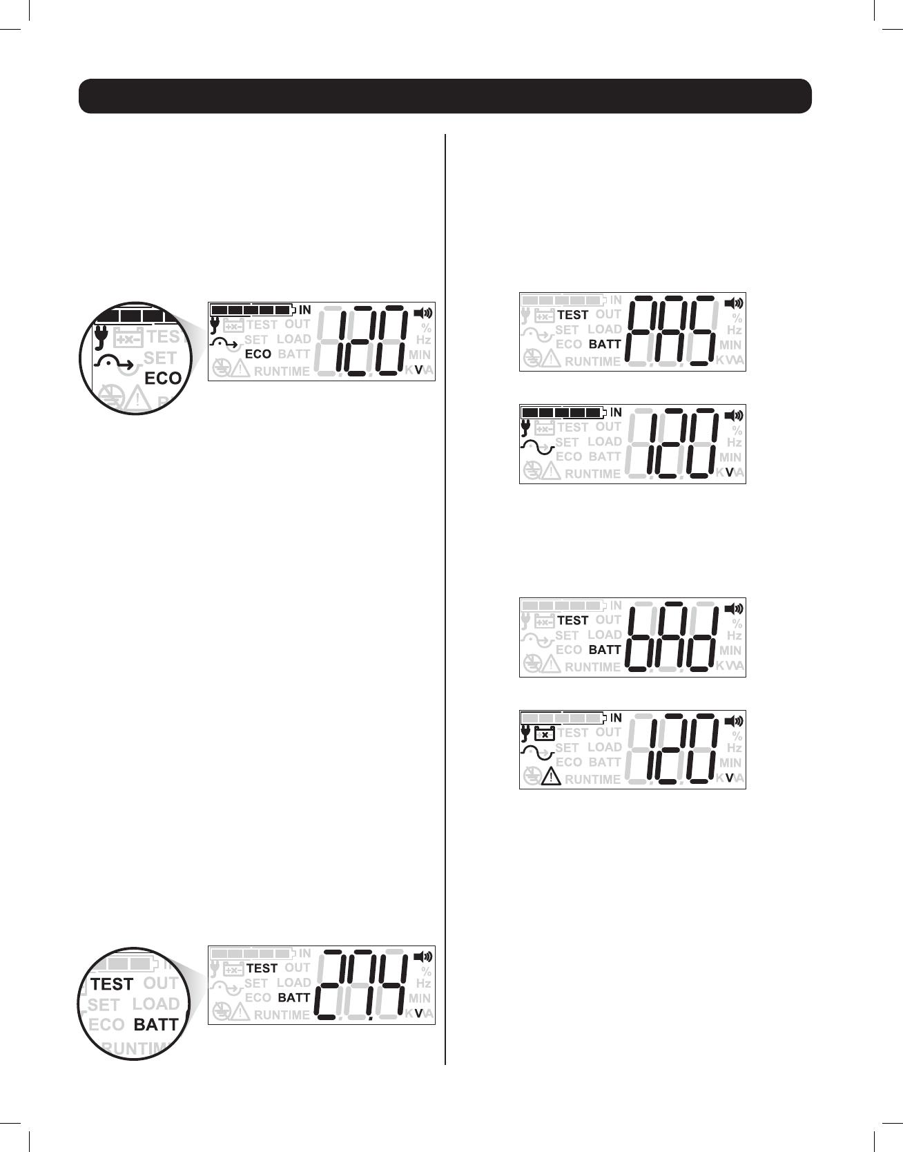
ECONOMY MODE SAMPLE LCD SCREEN
LCD ELEMENTS CONFIRMING ECONOMY MODE OPERATION
>ECOICON:ON(CONFIRMSECOMODEOPERATION)
>INPUTICON:ONSOLID(inputpowerispresent,bypassisavailable)
>INPUT ICON: FLASHING(inputpower is present, bypassisnot
available)
>BYPASS ICON: ON SOLID (confirms UPS is running in high-
efficiency mode)
>SINEWAVEICON:ONSOLID(confirmsUPSisrunninginon-line
mode)
ECONOMY MODE LCD VIEWING OPTIONS:
WhentheUPSisconfiguredforandenergizedintoECONOMYMODE,
the LCD screen will continue reporting the last viewed informational
screen (INPUT VOLTAGE shown). To display additional information
screens, tap the SETUP button repeatedly. The 10 available
informationscreensare(1)INPUTVOLTAGE,(2)INPUTFREQUENCY,
(3)OUTPUTVOLTAGE,(4)OUTPUTFREQUENCY,(5)LOADPERCENTAGE,
(6) LOAD KVA, (7) LOAD KW, (8) BATTERY CHARGE PERCENT, (9)
BATTERYVOLTAGE,(10)ESTIMATEDRUNTIME.
BATTERY TEST MODE:
To verify battery backup operation of your UPS, you can periodically
perform a manual or programmed self-test of the UPS system. To
manually initiate a self-test while the UPS is operating in On-Line or
Economy mode, press the ON button switch until a beep is heard, then
release. Self-test can also be initiated via PowerAlert software at user
determined intervals (see PowerAlert software documentation for more
information). When a self-test is run, the UPS will cycle to battery power
for approximately 10 seconds and automatically switch back to AC mode.
Once complete, the UPS will report the self-test results on the LCD
screen for about 10 seconds.
SELF-TEST MODE LCD VIEWING OPTIONS:
When a SELF-TEST is initiated, the UPS will flash the words “TEST”
&“BATT”anddisplaytheDCbatteryvoltageforabout10seconds.
No other informational screens are viewable until after the self-test
is complete and results are reported.
PASSED SELF-TEST
If the UPS and battery system pass the self test, the screen will report
“PAS” in the three character display and return to normal online /
economy operation with the last viewed informational screen.
PASS NOTIFICATION (10 SEC)
RETURN TO ONLINE / ECONOMY MODE (LAST VIEWED SCREEN)
FAILED SELF-TEST
If the UPS does not pass the selftest, the screen will report “BAD”
in the three character display and continue reporting the last viewed
informational screen.
FAIL NOTIFICATION (10 SEC)
RETURN TO ONLINE / ECONOMY MODE (LAST VIEWED SCREEN)
>THE“!”REMAINSLIGHTED
>THE“BATTERYWITHXTHROUGHIT”REMAINSLIGHTED
>THEBATTERYCHARGEICONREPORTS“ZEROBARS”
13-03-138 93-3168-EN.indd 18 3/28/2013 1:05:30 PM
19
FREQUENCY REGULATION & CONVERSION MODE
YourUPSiscompatiblewith100-127Vnominalinputvoltageateither
50or60Hz.InONLINEMODE,UPSoutputfrequencywilltrackinput
frequencybyasmuchas+/-5Hzbeforeswitchingtobatterymode.
TheUPSwillautomaticallyself-confirgurefor50Hzor60Hzoperation
basedonutilitypowerconditionsatstart-up(55to65Hzonstartup
resultsin60Hzconfiguration/45to55Hzonstartupresultsin50
Hzconfiguration/cold-startresultsin60Hzconfiguration).Frequency
regulation/conversionmodecanbeusedtoREGULATEfrequencyof
thesamenominal(suchas60Hzinputtoregulated60Hzoutput)or
toCONVERTfrequencyfromonenominaltoanother(suchas60Hz
to 50Hz, or 50Hz to 60Hz). Whenever frequency regulation /
conversion mode is turned ON, output frequency is regulated to
+/-0.05Hz of the selected nominal output frequency. Frequency
regulation / conversion mode is available for continuous operation
anytimeinputfrequencyisbetween40and70Hz.
In FREQUENCY REGULATION / CONVERSION MODE
Maximum UPS output is de-rated by 30%.
Frequency Regulation Settings Bypass is available
>SetFREQUENCYCONVERSIONtoON
>Set OUTPUT FREQUENCY to the same nominal as your input
frequency(toregulate60HzinUSA/Canada/Mexico,setoutputto
60Hz)
Frequency Conversion Settings Bypass is not available
>SetFREQUENCYCONVERSIONtoON
>SetOUTPUTFREQUENCYtoadifferentnominalasyourinput(to
produce50HzoutputinUSA/Canada/Mexico,setoutputto50Hz)
FREQUENCY REGULATION / CONVERSION MODE
LCD ELEMENTS CONFIRMING FREQUENCY REGULATION MODE
OPERATION
>SINEWAVEICON:BLINKING(CONFIRMSOUTPUTFREQUENCYIS
INDEPENDENTOFINPUTFREQUENCY)
> PLUG ICON: ON (CONFIRMS INPUT POWER IS PRESENT) &
BLINKING(CONFIRMSAUTO-BYPASSISNOTAVAILABLE)
Operation
13-03-138 93-3168-EN.indd 19 3/28/2013 1:05:31 PM
ECO
TEST
IN
OUT
LOAD
BATT
RUNTIME
!
SET Hz
A
%
MIN
K VV
ECO
TEST
IN
OUT
LOAD
BATT
RUNTIME
!
SET Hz
A
%
MIN
K VV
ECO
TEST
IN
OUT
LOAD
BATT
RUNTIME
!
SET Hz
A
%
MIN
K VV
ECO
TEST
IN
OUT
LOAD
BATT
RUNTIME
!
SET Hz
A
%
MIN
K VV
ECO
TEST
IN
OUT
LOAD
BATT
RUNTIME
!
SET Hz
A
%
MIN
K VV
V
ECO
TEST
IN
OUT
LOAD
BATT
RUNTIME
!
SET Hz
%
MIN
AKV
A
ECO
TEST
IN
OUT
LOAD
BATT
RUNTIME
!
SET Hz
%
MIN
KVV
A
ECO
TEST
IN
OUT
LOAD
BATT
RUNTIME
!
SET Hz
%
MIN
KVV
A
ECO
TEST
IN
OUT
LOAD
BATT
RUNTIME
!
SET Hz
%
MIN
K VV
A
ECO
TEST
IN
OUT
LOAD
BATT
RUNTIME
!
SET Hz
%
MIN
K VV
Press & Release SETUP
button (less than 1 sec.)
Press & Release SETUP
button (less than 1 sec.)
Press & Release SETUP
button (less than 1 sec.)
Press & Release SETUP
button (less than 1 sec.)
Press & Release SETUP
button (less than 1 sec.)
Press & Release SETUP
button (less than 1 sec.)
Press & Release SETUP
button (less than 1 sec.)
Press & Release SETUP
button (less than 1 sec.)
Press & Release SETUP
button (less than 1 sec.)
Press & Release SETUP
button (less than 1 sec.)
20
Operation
Note: Set of 10 information screens are shown in ON LINE MODE, but can also be viewed from all operating modes.
LCD Status & Supported Measurements
1st Screen:
UPS INPUT
VOLTAGE
2nd Screen:
UPS INPUT
FREQUENCY(HZ)
3rd Screen:
UPS OUTPUT
VOLTAGE
4th Screen:
UPS OUTPUT
FREQUENCY(HZ)
5th Screen:
UPS OUTPUT LOAD
PERCENTAGE
6th Screen:
UPS OUTPUT LOAD
KILOVOLTAMPS
(KVA)
7th Screen:
UPS OUTPUT LOAD
KILOWATTS (KW)
8th Screen:
UPSBATTERY
CHARGE
PERCENTAGE
9th Screen:
UPSBATTERY
VOLTAGE
10th Screen:
UPS ESTIMATED
RUNTIME AT
CURRENT LOAD
LEVEL(MINUTES)
Once the UPS is up and running, the front panel LCD screen can be set to display any of 10 available information and status screens.
To view the next available information screen, tap the SETUP button (less than 1 second). The display can be "parked" on a particular value
for full-time display while the UPS is running in that mode.
13-03-138 93-3168-EN.indd 20 3/28/2013 1:05:32 PM
  • Page 1 1
  • Page 2 2
  • Page 3 3
  • Page 4 4
  • Page 5 5
  • Page 6 6
  • Page 7 7
  • Page 8 8
  • Page 9 9
  • Page 10 10
  • Page 11 11
  • Page 12 12
  • Page 13 13
  • Page 14 14
  • Page 15 15
  • Page 16 16
  • Page 17 17
  • Page 18 18
  • Page 19 19
  • Page 20 20
  • Page 21 21
  • Page 22 22
  • Page 23 23
  • Page 24 24
  • Page 25 25
  • Page 26 26
  • Page 27 27
  • Page 28 28
  • Page 29 29
  • Page 30 30
  • Page 31 31
  • Page 32 32
  • Page 33 33
  • Page 34 34
  • Page 35 35
  • Page 36 36
  • Page 37 37
  • Page 38 38
  • Page 39 39
  • Page 40 40
  • Page 41 41
  • Page 42 42
  • Page 43 43
  • Page 44 44
  • Page 45 45
  • Page 46 46
  • Page 47 47
  • Page 48 48
  • Page 49 49
  • Page 50 50
  • Page 51 51
  • Page 52 52
  • Page 53 53
  • Page 54 54
  • Page 55 55
  • Page 56 56
  • Page 57 57
  • Page 58 58
  • Page 59 59
  • Page 60 60
  • Page 61 61
  • Page 62 62
  • Page 63 63
  • Page 64 64
  • Page 65 65
  • Page 66 66
  • Page 67 67
  • Page 68 68
  • Page 69 69
  • Page 70 70
  • Page 71 71
  • Page 72 72
  • Page 73 73
  • Page 74 74
  • Page 75 75
  • Page 76 76
  • Page 77 77
  • Page 78 78
  • Page 79 79
  • Page 80 80
  • Page 81 81
  • Page 82 82
  • Page 83 83
  • Page 84 84
  • Page 85 85
  • Page 86 86
  • Page 87 87
  • Page 88 88
  • Page 89 89
  • Page 90 90
  • Page 91 91
  • Page 92 92
  • Page 93 93
  • Page 94 94
  • Page 95 95
  • Page 96 96

Tripp Lite On-Line Tower LCD UPS User manual

Category
Uninterruptible power supplies (UPSs)
Type
User manual
This manual is also suitable for

Ask a question and I''ll find the answer in the document

Finding information in a document is now easier with AI