Page is loading ...

1
Owner’s Manual
SmartPro
®
3U Rackmount UPS
Model: SMX5000XLRT3U
(Series Number: AGSM5247)
Not suitable for mobile applications.
1111 W. 35th Street, Chicago, IL 60609 USA • www.tripplite.com/support
Copyright © 2019 Tripp Lite. All rights reserved.
SmartPro
®
is a registered trademark of Tripp Lite.
Important Safety ...............2
Instructions
Mounting ..........................3
Quick Installation ..............5
Optional Installation ..........7
Basic Operation ................9
Storage and Service .......13
Battery Replacement ......14
Español...........................16
Français ..........................31
Русский .........................46
18-08-323-932460.indb 1 2/13/2019 2:53:40 PM

2
Important Safety Instructions
SAVE THESE INSTRUCTIONS
This manual contains important instructions that should be followed during the
installation, operation and storage of all Tripp Lite UPS Systems. Failure to heed these
warnings may affect your warranty.
UPS Location Warnings
• Use caution when lifting your UPS. Because of the considerable weight of all rackmount UPS
systems, at least two people should assist in lifting and installing them.
• Install your UPS indoors, away from excess moisture or heat, dust or direct sunlight.
• For best performance, the ambient temperature near your UPS should be between 0° C and
40° C (between 32° F and 104° F).
• Leave adequate space around all sides of the UPS for proper ventilation. Do not obstruct its
vents or fan openings.
• Do not mount unit with its front or rear panel facing down (at any angle). Mounting in this
manner will seriously inhibit the unit’s internal cooling, eventually causing product damage not
covered under warranty.
UPS Connection Warnings
• The UPS contains its own energy source (battery). The output terminals may be live even when
the UPS is not connected to an AC supply.
Equipment Connection Warnings
• Use of this equipment in life support applications where failure of this equipment can
reasonably be expected to cause the failure of the life support equipment or to significantly
affect its safety or effectiveness is not recommended. Do not use this equipment in the
presence of a flammable anesthetic mixture with air, oxygen or nitrous oxide.
• Do not connect surge suppressors or extension cords to the output of your UPS. This might
overload the UPS and will void the surge suppressor and UPS warranties.
Battery Warnings
• Batteries can present a risk of electrical shock and burn from high short-circuit current.
Observe proper precautions. Do not dispose of the batteries in a fire. Do not open the UPS or
batteries. Do not short or bridge the battery terminals with any object. Unplug and turn off the
UPS before performing battery replacement. Use tools with insulated handles. There are no
user-serviceable parts inside the UPS. Battery replacement should be performed only by
authorized service personnel using the same number and type of batteries (Sealed Lead-Acid).
The batteries are recyclable. Refer to your local codes for disposal requirements or visit
http://www.tripplite.com/support/recycling-program for recycling information. Tripp Lite offers a
complete line of UPS System Replacement Battery Cartridges (R.B.C.).Visit Tripp Lite on the
Web at http://www.tripplite.com/products/battery-finder/ to locate the specific replacement
battery for your UPS.
• During hot-swap battery replacement, the UPS will not provide backup power in the event of a
blackout or other power interruptions.
• Do not operate UPS without batteries.
• When adding external battery packs connect only Tripp Lite-recommended battery packs of the
correct voltage and type. Do not connect or disconnect battery packs when the UPS is
operating on battery power.
18-08-323-932460.indb 2 2/13/2019 2:53:40 PM

3
Mounting
Your UPS may be rackmounted in 4- or 2-post racks. To mount the UPS (power module +
external battery module) in a 2-post rack, purchase the appropriate hardware, sold separately
(order Tripp Lite model # 2POSTRMKITHD). See 2POSTRMKITHD owner’s manual for installation
instructions. To mount the UPS in a 4-post rack, use the included hardware and follow the
procedure outlined below. The procedures are for common rack types and may not be appropriate
for all rack configurations. User must determine the fitness of rackmount hardware and
procedures before mounting.
CAUTION: Rackmount equipment may be extremely heavy—be careful when moving or
lifting equipment. Use one or more assistants if necessary.
4-Post Rack Mounting
Square-Hole Rack Installation
1
The included plastic pegs
A
will
temporarily support the empty
rackmount shelves
B
while you install
the permanent mounting hardware.
Insert a peg near the center of the
front and rear bracket of each shelf as
shown. (Each front bracket has 6 holes
and each rear bracket has 3 holes.)
The pegs will snap into place.
1
2
3
After installing the pegs, expand each shelf to match the depth of your rack rails. The pegs
will fit through the square holes in the rack rails to support the shelves. Refer to the rack unit
labels to confirm that the shelves are level in all directions.
Note: The support ledge of each shelf must face inward.
A
C
C
A
B
B
2
Secure the shelves
B
to the mounting
rails permanently using the included
screws and cup washers
C
as shown.
Place 6 screws total at the front and 4
screws total at the back.
Tighten all screws before proceeding.
Warning: Do not attempt to install
your equipment until you have
inserted and tightened the required
screws. The plastic pegs will not
support the weight of your
equipment.
3
Attach your equipment’s mounting
brackets to the forward mounting holes
of the cabinet using the hardware
included with your equipment. The
mounting bracket “ears” should face
forward. (Some equipment may have
pre-installed or integral mounting
brackets.)
18-08-323-932460.indb 3 2/13/2019 2:53:41 PM

4
4
With the aid of an assistant (if
necessary), lift your equipment and
slide it into the shelves. Attach the
equipment mounting brackets to the
forward mounting rails with user-
supplied screws and washers
D
.
Tighten all screws securely.
Mounting
Threaded-Hole Rack Installation
4
D
1
Align the mounting rail
A
along the
inside surface of the rack posts
B
so
that the flanges on the ends of the rail
wrap around to the front and rear
surfaces of the posts and the rail holes
meet the threaded holes on the rack
post.
2
Secure the shelves
A
to the mounting
rails permanently using user-supplied
screws and washers
C
for your rack as
shown. Place 6 screws total at the
front and 4 screws total at the back.
Tighten all screws before proceeding.
Warning: Do not attempt to install
your equipment until you have
inserted and tightened the required
screws.
1
B
A
A
B
3
Follow steps
3
and
4
of the Square-Hole Rack Installation instructions (above) to securely
mount your 3U equipment.
Tower Mounting
If you tower mount this UPS, it requires the addition of a
Tripp Lite 2U to 9U tower stand (model: 2-9USTAND, sold
separately). See owner’s manual for installation
procedure.
Rotate the power module’s Control Panel to view it easier
while the UPS is tower mounted. Insert a small
screwdriver, or other tool, in the slots on either side of the
Control Panel. Pop the panel out; rotate it; and pop the
panel back into place.
A
C
C
2
18-08-323-932460.indb 4 2/13/2019 2:53:45 PM

5
Quick Installation
DANGER!
HIGH VOLTAGE! RISK OF SERIOUS INJURY OR
DEATH! FOR QUALIFIED ELECTRICIANS ONLY!
ELECTRICIANS MUST READ WARNINGS BELOW
AND IN SAFETY SECTION PRIOR TO
INSTALLATION.
connection base step 1
1
Hardwire the UPS System’s
input terminals to a utility
power source.
1
A
B
Input and Output Ratings
Model Voltage Input Current Output Current Wire Size
SMX5000XLRT3U 230V 27A 30A 10 AWG
Before hardwiring, switch OFF the facility’s circuit breaker which is supplying power to the circuit
the UPS System will be connected to. Using a screwdriver, remove the top of the box
A
covering
the UPS System’s input terminals. Pass user-supplied cable through the opening in the box
B
and attach it to the terminals. After hardwiring is complete, switch ON the facility’s circuit breaker
which is supplying power to the circuit the UPS System is connected to. Please note that after the
UPS System is connected to a live utility power source, the UPS (in “Standby” mode) will
automatically charge its batteries,* but will not supply power to its outlets until it is turned ON
(see Step 3 below).
* The BATTERY CHARGE LED will be the only LED illuminated.
Note: UPS system will function properly upon initial startup; however, maximum runtime for the unit’s battery
will only be accessible after it has been charged for 24 hours.
HARDWIRE WARNINGS!
• Wiring must be done by a qualified electrician.
• When making wiring connections, observe the cable connection regulations appropriate to
your area at all times. Be sure to install an easily accessible disconnect switch in your
installation wiring so you may cut off the UPS’s AC input during fires and other
emergencies. Ensure that cables are fitted with cable sleeves and are secured by
connector clamps. Tighten connections with a torque of not less than 10 inch-pounds
(1.1 NM).
• Make sure that your equipment is properly grounded.
• Using cables of improper size may damage your equipment and cause fire hazards.
Choose appropriate cabling and protection circuits to make wiring connections (Ground
conductors must be the same size and type as the power conductors used).
18-08-323-932460.indb 5 2/13/2019 2:53:45 PM

6
Quick Installation
2
Plug your equipment into the
UPS.*
Plug your equipment into the UPS using the
additional power cord(s) that came with the UPS.
Note: Additional interconnection cords (C13 to C14) are
available from Tripp Lite. Visit tripplite.com
(Part # P004-006).
* Your UPS is designed to support only electronic equipment.
You will overload the UPS if the total VA ratings for all the
equipment you connect exceeds the UPS’s Output Capacity.
To find your equipment’s VA ratings, look on their
nameplates. If the equipment is listed in amps, multiply the
number of amps by 230 to determine VA. (Example:
1 amp × 230 = 230 VA). If you are unsure if you have
overloaded the UPS’s outlets, see “OUTPUT LOAD LEVEL”
LED description.
3
Turn the UPS ON.
Press and hold the “ON/OFF/STANDBY” button for one
second. The alarm will beep once briefly after one
second has passed. Release the button.
2
3
18-08-323-932460.indb 6 2/13/2019 2:53:46 PM

7
Optional Installation
These connections are optional. Your UPS will function properly without these
connections.
1a
1b
1
USB and RS-232 Serial Communications
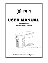
2
Relay Contact-Closure Connection
Use the included DB9 cable (see
2a
) to connect
specialized electronic equipment to the relay contact-
closure port on your UPS System. See diagram
2b
and
chart below to determine signals carried by this port.
Relay Contact Closure Chart
Line Fail
Indication
Mid Battery
Indication
Low Battery
Indication
UPS Operating
Conditions
Pins
1 & 6
Pins
2 & 6
Pins
7 & 3
Pins
8 & 3
Pins
4 & 9
Pins
5 & 9
AC Input Voltage OK CLOSED OPEN — — — —
AC Input Out of Range OPEN CLOSED — — — —
Battery More than 3
Min. Remaining Charge*
— — OPEN CLOSED — —
Battery Less than 3 Min.
Remaining Charge*
— — CLOSED OPEN — —
Battery More than 2
Min. Remaining Charge*
— — — — OPEN CLOSED
Battery Less than 2 Min.
Remaining Charge*
— — — — CLOSED OPEN
Contact Action Open on
Line
Failure
Close on
Line
Failure
Battery
Close
Below
Mid
Battery
Open
Below
Mid
Battery
Close
Below
Low
Battery
Open
Below
Mid
Battery
* Times are approximate, at full load.
LINE FAIL
K1 A
LO BATT
K1 0A
1
2
3
4
5
6
7
8
9
OPENS ON LI NE FA IL
CLOSES ON LINE FA IL
CLOSES BE LOW LOW BATTER Y
TOP OF DUAL
DB9 (J5/J34)
NO TE :
CLOSES BELOW MID BATTERY
J5
REMOTE CONTAC TS
COM
MID BAT
K4 A
COM
COM
OPENS
BELOW MID BATT ERY
RELA YS SHOW N DE-ENE RGIZ ED
OPENS BELOW LOW BATTERY
2a
2b
Use the included USB cable (see
1a
) and/or DB9
serial cable (see
1b
) to connect the communication
port on your computer to the communication port of
your UPS. Install on your computer the Tripp Lite
PowerAlert
®
software appropriate to your computer’s
operating system. Consult your PowerAlert manual for
more information.
18-08-323-932460.indb 7 2/13/2019 2:53:47 PM

8
Optional Installation
3
EPO Port Connection
This optional feature is only for those applications
which require connection to a facility’s Emergency
Power Off (EPO) circuit. When the UPS is connected
to this circuit, it enables emergency shutdown of the
UPS’s inverter.
Using the cable provided, connect the EPO port of
your UPS (see
3a
) to a user-supplied normally closed
or normally open switch according to the circuit
diagram (see
3b
). The EPO port is not a phone line
surge suppressor; do not connect a phone line to this
port.
4-5
connection base step 1
3a
3b
4a
4b
4
External Battery Connection
All UPS models come with a robust internal battery
system; select models feature connectors (see
4a
)
that accept optional external battery packs (sold
separately from Tripp Lite) to provide additional
runtime. Adding external batteries will increase
recharge time as well as runtime. See battery pack
owner’s manual for complete installation instructions.
Make sure cables are fully inserted into their
connectors. Small sparks may result during battery
connection; this is normal. Do not connect or
disconnect battery packs when the UPS is running on
battery power.
If you connect any external batteries, set the Battery
Charge Level Switch (see
4b
) to the down position.
This will increase your UPS’s charger output so the
additional batteries charge faster.
Note: the switch to the right of the Battery Charge Level
Switch is inactive and will not affect UPS operation regardless
of its position.
CAUTION! DO NOT set the Battery Charge Level
Switch to the down position without an external
battery connected. There is a risk of damaging
the UPS’s internal battery system.
18-08-323-932460.indb 8 2/13/2019 2:53:47 PM

9
Basic Operation
Buttons (Front Panel)
“ON/OFF/STANDBY” Button
When the UPS system is connected to a live AC utility power source, the UPS
System will operate in one of three modes: ON, OFF or STANDBY. Refer to the chart
below for UPS System operating characteristics within each mode.
Mode
UPS Charges Battery
(when utility is present)
UPS Supplies Power to
Outlets (when utility is
present or absent*) UPS Displays LEDs
ON Yes Yes Yes (variety of LEDs,
depending on conditions)
OFF No No No
STANDBY Yes No Yes (“BATTERY CHARGE”
LED only)
To place the UPS in the ON mode: First, have a qualified electrician connect the
UPS System to a utility power source as outlined in the Quick Installation section.
Once the utility power source is live, the UPS System will automatically enter
STANDBY mode. Press and hold the “ON/OFF/STANDBY” button for one second**
and then release it to switch the UPS System from STANDBY mode to ON mode.
OPTIONAL: If the utility power source is not live, you can “cold-start” the UPS
System (i.e.: switch it directly from the OFF mode to the ON mode by supplying
power for a limited time from its batteries*) by pressing and holding the “ON/
OFF/STANDBY” button for one second** and then releasing it.
To place the UPS in the OFF mode: With the UPS System in the ON mode and
receiving utility power, press and hold the “ON/OFF/STANDBY” button for one
second** and then release it to switch the UPS System from ON mode to
STANDBY mode. Switch OFF the facility’s circuit breaker which is supplying power
to the circuit the UPS System is connected to.
* If batteries are fully charged. ** The alarm will beep once briefly after the interval has passed.
“MUTE/TEST” Button
To Silence (or “Mute”) UPS Alarms: briefly press and release the MUTE/TEST
button.*
To Run a Self-Test: with your UPS connected to a live utility power source and
turned ON, press and hold the MUTE/TEST button for two seconds.* Continue
holding the button until the alarm beeps several times and the UPS performs a self
test. See “Results of a Self-Test” below.
Note: you can leave connected equipment on during a self-test. Your UPS, however, will not
perform a self-test if the UPS is not turned on (see “ON/OFF/STANDBY” Button description).
Results of a Self-Test: the test will last approximately 10 seconds as the UPS
switches to battery to test its load capacity and battery charge.
• If the “OUTPUT LOAD LEVEL” LED remains lit red and the alarm continues to
sound after the test, the UPS’s outlets are overloaded. To clear the overload,
unplug some of your equipment and run the self-test repeatedly until the
“OUTPUT LOAD LEVEL” LED is no longer lit red and the alarm is no longer
sounding.
CAUTION! Any overload that is not corrected by the user immediately
following a self-test may cause the UPS to shut down and cease supplying
output power in the event of a blackout or brownout.
18-08-323-932460.indb 9 2/13/2019 2:53:48 PM

10
Basic Operation
• If the “BATTERY WARNING” LED remains lit and the alarm continues to sound
after the test, the UPS batteries need to be recharged or replaced. Allow the UPS
to recharge continuously for 12 hours, and repeat the self-test. If the LED
remains lit, contact Tripp Lite for service. If your UPS requires battery
replacement, visit http://www.tripplite.com/products/battery-finder/ to locate the
specific Tripp Lite replacement battery for your UPS.
* The alarm will beep once briefly after the indicated interval has passed.
Indicator Lights (Front Panel)
All Indicator Light descriptions apply when the UPS is connected to a live utility power source and
turned ON.
“POWER” LED: this green LED lights continuously when the UPS is ON and
supplying connected equipment with AC power from a utility source. The LED
flashes and an alarm sounds (4 short beeps followed by a pause) to indicate the
UPS is operating from its internal batteries during a blackout or severe brownout. If
the blackout or severe brownout is prolonged, you should save files and shut down
your equipment since internal battery power will eventually be depleted. See
“BATTERY CHARGE” LED description below.
“VOLTAGE CORRECTION” LED: this green LED lights continuously whenever the
UPS is automatically correcting high or low AC voltage on the utility line without the
assistance of battery power. The UPS will also emit a slight clicking noise. These
are normal, automatic operations of the UPS, no action is required on your part.
“OUTPUT LOAD LEVEL” LED: this multicolored LED indicates the approximate
electrical load of equipment connected to the UPS’s AC outlets. It will turn from
green (light load) to yellow (medium load) to red (overload). If the LED is red (either
illuminated continuously or flashing), clear the overload immediately by unplugging
some of your equipment from the outlets until the LED changes from red to yellow
(or green).
CAUTION! Any overload that is not corrected by the user immediately may
cause the UPS to shut down and cease supplying output power in the event
of a blackout or brownout.
“BATTERY CHARGE” LED: when the UPS is operating from utility power, this LED
indicates the approximate charge state of the UPS’s internal batteries: red indicates
the batteries are beginning to charge; yellow indicates the batteries are roughly
midway through charging; and green indicates the batteries are fully charged. When
the UPS is operating from battery power during a blackout or severe brownout, this
LED indicates the approximate amount of energy (ultimately affecting runtime)
which the UPS’s batteries will provide: red indicates a low level of energy; yellow
indicates a medium level of energy; and green indicates a high level of energy.
Since the runtime performance of all UPS batteries will gradually deplete over time,
it is recommended that you periodically perform a self-test (see MUTE/TEST Button
description) to determine the energy level of your UPS batteries BEFORE a blackout
or severe brownout occurs. During a prolonged blackout or severe brownout, you
should save files and shut down your equipment since battery power will eventually
be depleted. When the LED turns red and an alarm sounds continuously, it
indicates the UPS’s batteries are nearly out of power and UPS shut down is
imminent.
18-08-323-932460.indb 10 2/13/2019 2:53:48 PM

11
Basic Operation
“BATTERY WARNING” LED: this LED lights red and an alarm sounds intermittently
after you complete a self test (See “MUTE/TEST” Button description) to indicate the
UPS batteries need to be recharged or replaced. Allow the UPS to recharge
continuously for 12 hours, and repeat the self-test. If the LED continues to light,
contact Tripp Lite for service. If your UPS requires battery replacement, visit
http://www.tripplite.com/products/battery-finder/ to locate the specific Tripp Lite
replacement battery for your UPS.
C13/230V
C19/230V
Charge Rate
Setting (when
External
Batteries are
not connected)
Charge Rate
Setting (when
External
Batteries are
connected)
Other UPS Features (Rear Panel)
AC Receptacles: Your UPS features C13 outlets, and select models also feature
C19 outlets. These output receptacles provide your connected equipment with AC
line power during normal operation and battery power during blackouts and
brownouts. The UPS protects equipment connected to these receptacles against
damaging surges and line noise. If you have a serial or USB connection to your
UPS, you can remotely reboot connected equipment by turning the receptacles
OFF and ON using Tripp Lite’s PowerAlert software.
Input Terminal block: Use these terminals to connect the UPS System to
utility power. Unscrew and remove the cover over the block for access.
Communications Ports (USB or RS-232): These ports connect your UPS to any
workstation or server. Use with Tripp Lite’s PowerAlert software and included cables
to enable your computer to automatically save open files and shut down equipment
during a blackout. Also use PowerAlert software to monitor a wide variety of AC line
power and UPS operating conditions. Consult your PowerAlert software manual or
contact Tripp Lite Customer Support for more information. See “USB and RS-232
Serial Communications” in the “Optional Installation” section for installation
instructions.
Relay Contact Interface Port: This female DB9 port sends contact-closure
signals to indicate line-fail and low battery status. See “Optional Installation”
section for installation instructions.
EPO (Emergency Power Off) Port: Your UPS features a EPO port that may be
used to connect the UPS to a contact closure switch to enable emergency inverter
shutdown. See “EPO Port Connection” in the “Optional Installation” section for
more information.
Battery Charge Level Switch: Controls the UPS system’s battery charge rate. If
you connect any external batteries, set the Battery Charge Level Switch to the
down position. This will increase your UPS’s charger output so the additional
batteries charge faster. Note: the switch to the right of the Battery Charge Level
Switch is inactive and will not affect UPS operation regardless of its position.
CAUTION! DO NOT set the Battery Charge Level Switch to the down position
without an external battery connected. There is a risk of damaging the
UPS’s internal battery system.
18-08-323-932460.indb 11 2/13/2019 2:53:49 PM

12
Basic Operation
Accessory Slot: Remove the small cover panel from this slot to install optional
accessories to remotely monitor and control your UPS. Refer to your accessory’s
manual for installation instructions. Visit tripplite.com for more information,
including a list of available SNMP, network management and connectivity products.
Power Sensitivity Adjustment: This dial is normally set fully counter-clockwise,
which enables the UPS to provide maximum protection against waveform
distortions in its AC input. When such distortion occurs, the UPS will normally
switch to providing sine wave power from its battery reserves for as long as the
distortion is present. In areas with poor utility power or where the UPS’s input
power comes from a backup generator, chronic waveform distortion could cause
the UPS to switch to battery too frequently, draining its battery reserves. You may
be able to reduce how often your UPS switches to battery due to moderate
waveform distortion by experimenting with different settings for this dial. As the dial
is turned clockwise, the UPS becomes more tolerant of variations in its input
power’s AC waveform.
Note: The further the dial is adjusted clockwise, the greater the degree of waveform distortion
the UPS will allow to pass to connected equipment.
When experimenting with different settings for this dial, operate connected
equipment in a safe test mode so that the effect on the equipment of any
waveform distortions in the UPS’s output can be evaluated without disrupting
critical operations.
External Battery Connector: Use to connect Tripp Lite external battery packs for
additional runtime. Refer to instructions available with the battery pack for
complete connection information and safety warnings.
Output Breaker(s): Protect your UPS from output overload. If one or more
breakers trip, remove some of the load on the circuit(s), then reset them by
pressing the breaker switch(es) in.
Ground Screw: Use this to connect any equipment that requires a chassis ground.
18-08-323-932460.indb 12 2/13/2019 2:53:49 PM

13
Storage and Service
Storage
Before storing your UPS, turn it completely OFF. If you store your UPS for an extended period of
time, recharge the UPS batteries for 4 to 6 hours once every three months. Note: after you
connect the UPS to utility power, it will automatically begin charging its batteries. If you leave
your UPS batteries discharged for an extended period of time, they will suffer a permanent loss of
capacity.
Service
Before returning your UPS for service, follow these steps:
1. Review the installation and operation procedures in this manual to insure that the service
problem does not originate from a misreading of the instructions. Also, check that the UPS
System’s circuit breaker(s) are not tripped. This is the most common cause of service inquiries
which can be easily remedied by following the resetting instructions in this manual.
2. If the problem continues, do not contact or return the product to the dealer. Instead, visit
www.tripplite.com/support.
3. If the problem requires service, visit www.tripplite.com/support and click the “Request Return
(RMA)” link. From here you can request a Returned Material Authorization (RMA) number,
which is required for service. This simple on-line form will ask for your unit’s model and serial
numbers, along with other general purchaser information. The RMA number, along with
shipping instructions will be emailed to you. Any damages (direct, indirect, special or
consequential) to the product incurred during shipment to Tripp Lite or an authorized Tripp Lite
service center are not covered under warranty. Products shipped to Tripp Lite or an authorized
Tripp Lite service center must have transportation charges prepaid. Mark the RMA number on
the outside of the package. If the product is within its warranty period, enclose a copy of your
sales receipt. Return the product for service using an insured carrier to the address given to
you when you request the RMA.
18-08-323-932460.indb 13 2/13/2019 2:53:49 PM

14
Battery Replacement
WEEE Compliance Information for Tripp Lite Customers and Recyclers (European Union)
Under the Waste Electrical and Electronic Equipment (WEEE) Directive and implementing
regulations, when customers buy new electrical and electronic equipment from Tripp Lite they are
entitled to:
• Send old equipment for recycling on a one-for-one, like-for-like basis (this varies depending on
the country)
• Send the new equipment back for recycling when this ultimately becomes waste
Battery replacement should be performed only by authorized service personnel using the same
number and type of batteries (sealed Lead-Acid). Under normal conditions, the original batteries
in your UPS will last many years. See Safety section before replacing batteries. The batteries are
designed for hot-swap replacement (i.e. leaving the UPS in ON mode), but some qualified service
personnel may wish to put the UPS in the OFF mode and disconnect equipment before
proceeding.
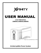
Procedure
1
Remove Front Panel and Battery Holding Plate
2
Disconnect Batteries
3
Remove/Dispose of Batteries
4
Add Batteries
5
Connect Batteries
Attach connectors: black-to-black and red-to-red.
6
Replace Front Panel
WARNING!
Batteries can present a risk of electrical shock
and burn from high short-circuit current result-
ing in serious injury or death. Battery terminals
are in close proximity to UPS cabinet and spe-
cial care must be taken to avoid shorting the
batteries including not touching metal
cabinet and battery terminals simultaneously.
2 5
1 6
3 4
UPS and Battery Recycling
Please recycle Tripp Lite Products. The batteries used in Tripp Lite products are sealed Lead-
Acid batteries. These batteries are highly recyclable. Please refer to your local codes for disposal
requirements.
You can call Tripp Lite for recycling info at 1-773-869-1234.
You can go to the Tripp Lite Website for up-to-date information on recycling the batteries or any
Tripp Lite product. Please follow this link: http://www.tripplite.com/support/recycling-program/
18-08-323-932460.indb 14 2/13/2019 2:53:49 PM

15
Regulatory Compliance Identification Numbers
For the purpose of regulatory compliance certifications and identification, your Tripp Lite product has been
assigned a unique series number. The series number can be found on the product nameplate label, along
with all required approval markings and information. When requesting compliance information for this product,
always refer to the series number. The series number should not be confused with the marketing name or model
number of the product.
Tripp Lite has a policy of continuous improvement. Specifications are subject to change without notice.
Note on Labeling
Two symbols are used on the label.
V~ : AC Voltage
V : DC Voltage
1111 W. 35th Street, Chicago, IL 60609 USA • www.tripplite.com/support
18-08-323 • 93-2460_revD
18-08-323-932460.indb 15 2/13/2019 2:53:50 PM

46
Стоечный ИБП
семейства SmartPro
®
высотой 3U
Модель: SMX5000XLRT3U
(Номер серии: AGSM5247)
1111 W. 35th Street, Chicago, IL 60609 USA • www.tripplite.com/support
19
Tripp Lite
SmartPro
®
Tripp Lite
.......47
............................48
.............50
.....52
....54
...58
.................59
English ..............................1
Español...........................16
Français ..........................31
18-08-323-932460.indb 46 2/13/2019 2:54:07 PM
/