Page is loading ...

SwitchLinc 2-Way
TM
Remote Control Switch
and Transmitter
For models:
#2383W SwitchLinc 2-Way 5-Amp (White)
#2383I SwitchLinc 2-Way 5-Amp (Ivory)
About SwitchLinc’s Certification
SwitchLinc has been thoroughly tested by ITS ETL SEMKO, a
nationally recognized independent third-party testing
laboratory. Products bearing North American ETL Listed
mark signifies that the product has been tested to and has
met the requirements of a widely recognized consensus of
U.S and Canadian product safety standards, that the
manufacturing site has been audited, and that the
manufacturer has agreed to a program of quarterly factory
follow-up inspections to verify continued conformance.
Smarthome Limited Warranty
Smarthome warrants to the original consumer purchaser of this product that, for a period of two years
from the date of purchase, this product will be free from defects in material and workmanship and will
perform in substantial conformity to the description of the product in this Owner's Manual. This warranty
shall not apply to defects or errors caused by misuse or neglect.
If the product is found to be defective in material or workmanship or if the product does not perform as
warranted above during the warranty period, Smarthome will either repair it, replace it or refund the
purchase price, at its option, upon receipt of the product at the address below, postage prepaid, with
proof of the date of purchase and an explanation of the defect or error. The repair, replacement, or
refund that is provided for above shall be the full extent of Smarthome's liability with respect to this
product.
For repair or replacement during the warranty period, call Smarthome customer service to receive an
RA# (return authorization number), properly package the product (with the RA# clearly printed on the
outside of the package) and send the product, along with all other required materials, to:
Smarthome
ATTN: Receiving Dept.
16542 Millikan Ave
Irvine, CA 92606-5027
Limitations:
THE ABOVE WARRANTY IS IN LIEU OF AND SMARTHOME DISCLAIMS ALL OTHER WARRANTIES,
WHETHER ORAL OR WRITTEN, EXPRESS OR IMPLIED, INCLUDING ANY WARRANTY OF
MERCHANTABILITY OR FITNESS FOR A PARTICULAR PURPOSE. ANY IMPLIED WARRANTY, INCLUDING
ANY WARRANTY OF MERCHANTABILITY OR FITNESS FOR A PARTICULAR PURPOSE, WHICH MAY NOT BE
DISCLAIMED OR SUPPLANTED AS PROVIDED ABOVE SHALL BE LIMITED TO THE ONE YEAR PERIOD OF
THE EXPRESS WARRANTY ABOVE. NO OTHER REPRESENTATION OR CLAIM OF ANY NATURE BY ANY
PERSON SHALL BE BINDING UPON SMARTHOME OR MODIFY THE TERMS OF THE ABOVE WARRANTY
AND DISCLAIMER.
IN NO EVENT SHALL SMARTHOME BE LIABLE FOR SPECIAL, INCIDENTAL, CONSEQUENTIAL OR OTHER
DAMAGES RESULTING FROM THE POSSESSION OR USE OF THIS PRODUCT, INCLUDING WITHOUT
LIMITATION DAMAGE TO PROPERTY AND, TO THE EXTENT PERMITTED BY LAW, PERSONAL INJURY, EVEN
IF SMARTHOME KNEW OR SHOULD HAVE KNOWN OF THE POSSIBILITY OF SUCH DAMAGES.
Some states do not allow limitations on how long an implied warranty lasts and/or the exclusion or
limitation of damages, in which case the above limitations and/or exclusions may not apply to you. You
may also have other legal rights, which may vary from state to state.
© Copyright 2003 Smarthome, 16542 Millikan Ave., Irvine, CA 92606-5027
800.SMART.HOME - 949.221.9200 - www.smarthome.com
rev 100603

Congratulations !
You’ve just purchased the highest quality powerline-controllable wall switch available.
SwitchLinc 2-Way Switch is the world’s first two-way powerline remote control switch. It gives
you remote control of lighting and inductive loads. It is also a transmitter, so it can be used to
control other SwitchLincs, KeypadLincs, and LampLinc modules in lighting “scenes” or to trigger
home automation “events”. It responds to status request signals over the powerline to provide
feedback to a controller that the signal was received and executed. Normally, this is a feature
only found in expensive hardwired lighting systems.
The SwitchLinc 2-Way Switch can also be controlled remotely from a powerline transmitter.
Each SwitchLinc 2-Way Switch can be a member of up to 64 lighting scenes, allowing one
powerline signal to set elegant “mood lighting.” The SwitchLinc’s X10/PLC address is
electronically set; there are no code wheels on the unit to adjust.
SwitchLinc 2-Way Switch is easily installed and programmed. It installs (connects to home
wiring) just like a regular light switch. This makes it ideal for retrofits into existing homes and it
easily installs in new homes, with no special training required.
Key Features
• True rocker action (top = on, bottom = off)
• 2-Way communications
• Scene-ready
• All settings are held in non-volatile memory (no code wheels to set)
• High quality micro switches give the user tactile feedback
when pressed (no mushy feel)
• 8-level LED “Bar” shows if the load is on or off
• Status LED/ Set Button shows powerline activity & facilitates programming
• Wires in just like a standard wall switch (Requires a neutral connection)
Other SwitchLinc Models
SwitchLinc 2-Way 600-Watt Dimmer #2380W/I - (White or Ivory)
SwitchLinc 2-Way 1,000-Watt Dimmer #2381W/I - (White or Ivory)
SwitchLinc Plus Dimmer #2386W/I - (White or Ivory)
SwitchLinc PLC Dimmer #2384W/I - (White or Ivory)
SwitchLinc Switch #2385W/I - (White or Ivory)
SwitchLinc Deluxe Dimmer (No PowerLine Control) #2387W/I - (White or Ivory)
SwitchLinc Multi-Way Companion Switch for 3-Way, 4-Way, & Up circuits #2382W/I - (White/Ivory)
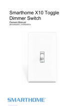
Brightness LED “Bar”
Status LED/Set Button
and Nightlight
Other Smarthome
Products
Your SwitchLinc Switch is
compatible with many of
our other home automation
products. If you need a
more traditional-looking
wall switch, check out the
new ToggleLinc series of
wall switches or the new
SwitchLinc RX, which is
ideal for retrofit
applications where there
isn't a neutral wire at the switch's wall box. The KeypadLinc Wall Mounted Transmitter
allows you to control multiple devices from one location at the press of a single button.
And for plug-in devices, the ApplianceLinc and LampLinc modules will automate just
about anything that plugs in. Please visit the Smarthome web site or contact your
distributor for more information.
2
Specifications
• Load types: Permanently installed incandescent, inductive, and
fluorescent
• Operation: Triac (12-amp Rated)
• Maximum load: 600 watts / 5 Amps
• Input power: 120 VAC, 60 Hz
• Connections (16 AWG): Black (to line), Red (to load), White (to neutral, required)
Yellow (to optional Multi-way Companion Switches, 2382)
• Addresses: 1 PLC (X-10) Base (Primary) Address of 256 possible
Up to 64 PLC (X-10) Scene Addresses of 255 possible
• Maximum SwitchLincs
per gang box: 4
• Maximum number of 10 (with more than 5, a PLC amplified
SwitchLincs per circuit: coupler-repeater is highly recommended)
• Minimum load: No minimum load required
• Operating temperature range: 40OF to 104OF
• Minimum PLC transmit level: 2V
• Minimum PLC receive level: 10mV
• Maximum PLC signal rejection: 200mV
• Mounting: Mounts in single or multiple-ganged J-box (200W of load
control is lost on 600W SwitchLinc for each immediately
adjacent switch installation; e.g., 600W load control becomes
400W with a switch to the immediate right or left. To avoid
downgrading load control, use a triple-gang box.
• Status indicator: Green LED
• On indicator: 8 Green LEDs (only the top and bottom LEDs will illuminate)
• Dimensions: Front Bracket Main Body
(Width) 1.73” 1.74”
(Height) 4.14” 2.71”
(Depth) 1.73” 1.40”
• Weight 4.0 oz
• Safety tested for use in the U.S. and Canada
Invest in better Home
Automation Products
Unlike most electric items, many PLC-
based products haven't changed much
over the years.
We, here at Smarthome, were disappointed with the quality
and robustness of the current crop of products. Our Marketing
and Customer Service teams surveyed our customers, like you,
and our engineers have invented new and better wall switches
and plug-in modules. We include more features, higher load
handling, and better signal sensitivity for a superior user
experience. While in some cases, they cost more; we hope
you'll agree that not having to replace a dead module every
couple years is worth the added expense and reduced
aggravation. Please visit a retailer or distributor for the
complete line of automation products from Smarthome Design.
KeypadLinc 6 with
450W integrated
dimmer
15

CAUTION!!
Read and understand these instructions before installing.
•This device is intended for installation in accordance with the National Electric Code
and local regulations in the United States, or the Canadian Electrical Code and local
regulations in Canada.
•For indoor use only.
•Connect only copper or copper-clad wire to this device.
•Before installing, disconnect power at circuit breaker or remove fuse to avoid shock or
damage to the control.
•It is recommended that a qualified electrician perform this installation.
•Retain these instructions for future reference.
Dimming an inductive load (such as a ceiling fan) below the minimum voltage set by the
manufacturer of the load device could cause damage to the load device from overheating.
If the manufacturer of the load device does not recommend dimming, DO NOT use
SwitchLinc 2-Way dinner with that device (use SwitchLinc 2-Way 5-Amp Switch #2383W/I
or 5-Amp Switch #2385W/I). USER ASSUMES ALL RISKS ASSOCIATED WITH DIMMING
AN INDUCTIVE LOAD.
Gradateurs commandant une lampe a filament de tungstene - afin de reduire le risque of
surchauffee et la possibilite d'endommagement a d'autres materiels, ne pas installer pour
commander une prise, un appareil a monteur, une lampe fluorescente ou un appareil
alimente par un transformateur.
Quick Start Instructions DEFAULT
Setting the 1. Press and hold the Set Button for 3 A-1
Primary Address seconds (the LED will begin blinking
and the load will come on)
2. Send the desired address from any
transmitter within 30 seconds
(see page 6 for more detailed instructions)
Factory Reset 1. Gently pull the Set Button out
to remove power for 5 seconds
2. Push and hold in the Set Button Resets to
for 5 seconds, then release default
3. When the LED Indicator comes on, settings
the SwitchLinc is reset
(see page 9 for more detailed instructions)
Programming a Scene 1. Transmit the “clear” sequence:
2. Activate the switch by turning it on
3. Send the following command sequence:
4.Transmit the desired scene address
(house and unit code) to lock-in the new scene.
(see pages 6 & 7 for more detailed instructions)
3
O16 N16 M16 P16 M16
M16 N16 O16 P16
Troubleshooting & Technical Support
Possible Cause
SwitchLinc was triggered by a
scene
It is normal for triac-based wall
switches to get warm
SwitchLinc may be in Program
Disable mode
SwitchLinc may not be “activated”
(has not been manipulated within
the last 4 minutes)
SwitchLinc may be in Disable
PLC Transmit mode
Other X10 transmitters are
loading down the circuit
Make sure the SwitchLinc can
transmit
Surge in power line
SwitchLinc is in system off position
Incomplete (open) wire
connection in wall box
Incomplete (open) wire
connection at fixture
The 2383 SwitchLinc Switch
does not have the ability to dim
or send dim signals
SwitchLinc needs a neutral wire
in order to operate.
The CLEAR or SET commands
were not sent in the correct order
Check the Status LED/Set Button
Move the transmitter to another
outlet
The triac inside the SwitchLinc
needs to turn off the electricity to
the load 120 times per second to
‘listen’ for X10 signals. This
causes the electricity going to the
load to be slight choppy.
The load is producing electrical
noise and it is interfering with
SwitchLinc’s reception of X10
signals
Solution
Check scene membership and remove unwanted
scenes from SwitchLinc, or perform a Factory
Reset to reset SwitchLinc to factory defaults
Install an X10 Signal Blocker for the home
SwitchLinc will dissipate 1-watt per 100 watts
controlled. Using metal junction boxes, removing
insulation around the outside of the box, or using a
small load can help lessen the heat
Re-enable Program mode or perform a Factory
Reset to reset SwitchLinc to factory defaults
Manually turn SwitchLinc ON or OFF or send its
X10 address during Step 2 of programming
Re-enable PLC Transmit mode or perform a Factory
Reset to reset SwitchLinc to defaults
Install a coupler-repeater (see page 10 for more
info)
The similar-looking SwitchLinc Plus and PLC
switches can’t transmit
Reset SwitchLinc by pulling out the Set Button for a
minute and then pressing it in
Press in the Set Button/Status LED
Check wall box wires to ensure all connections are
tight and no bare wires are exposed
Check fixture to ensure all connections are tight
and no bare wires are exposed
If you load can be dimmed without damaging it,
consider using the 2380 SwitchLinc 2-Way
Dimmer
Look in the rear of the junction box for a group of
white wires all tied together with a wire nut. Those
are the neutral wires; connect the SwitchLinc’s
white wire there
Don’t hold down the buttons too long, it may send
duplicate codes (i.e. two O16 codes)
It will blink when there is any X10 activity on the line
SwitchLinc needs at least 10mV of signal strength
for reliable operation, (50mV is better),a amplifier
or a signal bridge may be needed (see pg.10)
The bulbs filaments are vibrating. Using rough
service, 130-volt, or appliance grade bulbs will
reduce the noise
Consider using a SwitchLinc Relay. These models
have a hard contact relay and don’t contribute to a
noisy load.
Install a noise filter like Smarthome #4835 between
the load and the SwitchLinc or increase the signal
strength with a coupler-repeater to overcome the
line noise
Problem
Light controlled by
SwitchLinc turned
itself ON
The switch is getting
too warm to the touch
SwitchLinc will not take
programming of a
scene.
SwitchLinc is not
transmitting (will not
control a scene)
SwitchLinc is locked up
LED is not visible and
or SwitchLinc is not
controlling the light
SwitchLinc is unable to
brighten or dim other
modules
Existing switch only has
two wires
Difficulty setting scenes
with a maxi-controller
SwitchLinc is not
receiving signals
The load is buzzing
when on
SwitchLinc turns on, but
not off by X10 control
If these solutions have been tried, the manual has been reviewed and you still cannot
resolve an issue you’re having with the SwitchLinc;
• Search our on-line knowledge base at: http://smarthome.custhelp.com
•E-mail [email protected]
•Call our Technical Support Dept. at 949-221-9200
14

Preparation
Before installing SwitchLinc, please familiarize yourself with the following and take the
necessary precautions listed here:
• Be sure that the fuse has been removed or the circuit breaker is turned off to the
circuit being controlled. Installing SwitchLinc with the power on will expose you to
dangerous voltages.
• SwitchLinc Wiring Diagram on page 5 will help you to determine the wire colors of the
connections to the SwitchLinc and Multi-Way Companion Switch. Note: While the
neutral connection is optional on the Multi-Way Companion Switch, the SwitchLinc
2-Way requires a neutral connection.
• Wiring for 3-way, 4-way, & up switch circuits follow conventional (standard, non-remote)
wiring practice (plus the requirement for a neutral). Wiring the SwitchLinc Multi-Way
Companion Switch requires the Line (Black) wire be accessible and be the same 110V
leg of the house wiring. The white wire on the Multi-Way Companion Switch is to be
connected to NEUTRAL ONLY. If neutral is not available, cap the white wire, which will
simply causes the nightlight LED not to function.
• The SwitchLinc may feel warm during operation. The amount of heat generated is
within ETL approved limits and poses no hazards. To minimize heat build-up, ensure
that the area surrounding the rear of the SwitchLinc has adequate ventilation (i.e.,
clear away excess insulation).
• Installation should be performed only by a qualified electrician, or by a homeowner
who is familiar and comfortable with electrical circuitry. If there are any questions,
consult an electrician or contact Smarthome's Tech Support department for guidance.
Using SwitchLinc
Step-by-Step Instructions
1. Disconnect the power for the existing switches at the circuit breaker or fuse panel.
Verify that the power has been removed by trying to turn on the lights controlled by
the switches.
4
Input at Switch Output at Bulb PLC Transmission
Double-tap
top of rocker Light turns
ON Housecode & Unit Code (once)
Housecode & ON (twice)
Triple-tap
top of rocker Light turns
ON Housecode & Unit Code (once)
Housecode & ON (three times)
Double-tap
bottom of rocker Light turns
OFF Housecode & Unit Code (once)
Housecode & OFF (twice)
Triple-tap
bottom of rocker Light turns
OFF Housecode & Unit Code (once)
Housecode & OFF (three times)
Advanced Operations
Input at Switch Output at Bulb PLC Transmission
Tap top of rocker
(when light is off) Light turns
ON Housecode & Unit Code
Housecode & ON
Tap top of rocker
(when light is on) Light remains
ON Housecode & Unit Code
Housecode & ON
Tap bottom
of rocker Light turns
OFF Housecode & Unit Code
Housecode & OFF
Basic Operations
Glossary of Terms
PLC- Power Line Control- A control signal that is embedded onto the electricity lines.
X10 signals are a form of PLC signals.
X10 Address- The Address part of an X10 signal contains the House and Unit code.
An Address can be Unit codes 1 to 16 and House codes A - P. There are 256 total
X10 addresses. Examples of X10 Addresses are A-1, B-5, P-15, O-9.
X10 Command- The Command is action part of an X10 signal. It tells the module what
to do when it sees its address. Examples of a command are ON, OFF, Bright, DIM,
PREdim, All Light ON, and All Units OFF. There are other rarely used commands, but
these are the most common ones.
Status & Status Request- Some X10 receivers, like SwitchLinc 2-Way Dimmer and
Switch, have the ability to report their status when asked. These modules contain
transmitters that can send X10 signals. When a transmitter sends a Status Request
command, the module will reply with its status (On, Off, Predim at some %).
Resume Dim Level- If set, the SwitchLinc can come on to the level it was at before it
was turned off. (Not used in the non-dimmable SwitchLinc Switch)
PreDim Level- One of 32 brightness levels the SwitchLinc supplies to lights. When a
scene address is received, the SwitchLinc can instantly (or slowly) change the light’s
brightness to a predefined brightness level. (Not used in the non-dimmable SwitchLinc Switch)
Scenes in SwitchLincs- SwitchLincs Wall Switches can be set up to respond to
multiple X10 signals and when received come onto a predefined brightness level all
with one signal. One scene signal from a KeypadLinc or any transmitter can instantly
(within seconds) change the lighting mood in your home.
Maxi Controller- An X10 transmitter that has separate buttons for the unit codes and
the commands. In some of the advanced set up functions for the SwitchLinc, it is
necessary for only a unit code to be sent. The X10 SC-503, Leviton 6320, Stanley
370-2549 are examples of Maxi-Controllers. We recommend having a Maxi
Controller to set up the SwitchLinc.
X10 Keypress- This is an X10 signal that only contains the house and unit code
WITHOUT a command. The Maxi-Controller, some TouchLinc LCD controllers and
home automation interfaces can produce a keypress command.
Appliance Module- An X10 receiver device that can be used with any type of load,
including lighting. It will never contain dimming control as it always has a hard
contact relay. An Appliance Module will ignore the All Lights ON command.
Lamp Module- An X10 receiver that is used to control only lighting devices. It may
contain dimming control or it may have a hard contact relay. A Lamp Module will
respond to the All Lights ON command.
Hot or Line- The wire in the junction box that contains the incoming electricity from the
electrical panel. It is usually black and may be tied with a wire nut to other black
wires in the rear of the box.
Load- The wire in the junction box that goes to the light(s). Usually, there is just one
load wire in a junction box and it is black. It has no voltage when the switch is off.
Neutral- While not used on a mechanical switch to control a load, SwitchLinc will need
a neutral wire to operate. Generally, the neutral wires are white and located in the
rear of the junction box. There may be two or more wires tied together by a wire nut.
13

2. Remove the trim plate from the existing switches.
3. Unscrew and pull the existing switches from the wall box.
4. Disconnect the wires from the existing switches.
5. If the SwitchLinc is being installed into a 3/4/5-way
circuit, the SwitchLinc Multi-way Companion Switch must
be installed in the wall box where power comes into the
circuit. Follow the instruction included with the Multi-way Companion Switch to
identify the "Hot," "Neutral," "Ground," and "Traveler" wires.
6. Before making any connections to SwitchLinc, gently pull the Set Button until a
click is heard. This will open the “air gap” and isolate the SwitchLinc from the
electricity when the circuit breaker is turned back on.
7. Orient SwitchLinc so the LED is at the top and make connections according to the
“SwitchLinc Wiring Diagram” below. Wire Multi-way Companion Switches (if used)
according to the “SwitchLinc Multi-Way Wiring Diagram” below.
8. After all connections have been made, ensure that all wire connectors are firmly
attached and that there is no exposed copper except for the Ground wire.
9. Gently place the wires and switch into the wall box (with LED at top) and screw into
place.
10. Turn the circuit breaker back on.
11. Restore power to the circuit by pressing in the SwitchLinc’s Status LED/ Set Button
top until it is even with the front plastic trim ring. SwitchLinc will be operational
when the green Status LED will comes on.
12. After testing SwitchLinc for proper operation, install the faceplate (sold separately).
5
Note: When installing multiple SwitchLincs in a J-box, or many on the same
circuit breaker, please see specifications at the end of this manual for
limitations and recommendations.
Tip:
For additional help
installing 3-way circuits,
see page 5 in the
Multi-way Companion
Switch manual.
SwitchLinc 2-Way
Model# 2383
Helpful Tools (continued)
Voltmeter or Voltage Tester
During the installation of SwitchLincs, it may be necessary to identify the wires inside the
wall box. Knowing for sure which wire is the HOT or LINE wires can reduce the guesswork
when installing a single switch and it absolutely necessary when working with 3-way
lighting circuits. A voltmeter is ideal for this application. Many of the digital models can
also read current so you'll know how much power is being drawn by the SwitchLinc's load.
A simpler measurement tool, available at most home improvement centers, is a voltage
sensor. This device, often costing less than $20, can sense voltage when its tip is placed
near a wire. The tip of the voltage sensor can tell if voltage is inside the wire without
touching the bare copper conductor or breaking the insulation.
When using these tools, be certain to read and understand the safety instructions.
Often when these tools are used, the power to the circuit will need to be turned on.
When working around live electrical wires, take your time and concentrate on the task.
Helpful Hints for New Construction
By design, X10 equipment does not need much in the way of special wiring. The following
are six items we recommend for all homes with X10 installations:
1. Ask the builder or electrician to run the neutral wire to each wall switch location. This
wiring may be a code requirement or a regular practice in your area, but unless explicitly
specified, it may get omitted. Most SwitchLincs and all KeypadLinc controllers require the
neutral connection.
2. Specify the installation of deep J-boxes in all locations where X10 switches,
receptacles, or transmitters will be used. While all X10 products fit in the spacing offered
by all North American electrical boxes, the deep models have extra working space and
make the installation go a little easier. Deep boxes only costs a few cents more than
normal depth models. Look for single gang boxes that are 22cu or higher (cubic inches)
and double gang boxes that are 36cu or higher.
3. If the SwitchLinc is going to be controlling 400 watts or more, do not place insulation
around the wall box and consider using metal junction boxes. Dimmers that control high
loads will dissipate heat that may be felt through the switch faceplate. Metal boxes will
more efficiently draw out the heat and spread it over all the surfaces of the box. By
keeping wall insulation four inches from the box, free air will help move the heat away
from the switch and box.
4. Install a whole-house surge suppressor. Adding one whole-house surge protector at
the breaker will help protect against costly damage to the X10 components and other
delicate electrical equipment.
5. Install an X10 phase coupler (signal bridge) or coupler-repeater (amplifier) at the
incoming electrical service. A common problem with X10 signals is getting the signals
between the two legs of electricity that service the home. A coupler-repeater is
recommend for homes of 3,000 square feet or greater. Smaller homes will work well with
a passive phase coupler.
6. Work with the electrician to isolate non-automation loads. Ask the electrician to place
the non-X10 carrying lines on one of the two incoming lines. Having the kitchen and
laundry appliances plus the heating systems on one phase will help keep potential noise
off the X10 carrying lines. He probably won't be able to accommodate 100% of the loads
on one phase or another, but an attempt should be made.
12

Setting the Primary Address
Each SwitchLinc requires a primary address to operate. It ships from the factory with
“A1” as the default address; it will also have this address after performing a factory
reset. Any of the 256 PLC/X10 addresses can be programmed.
The SwitchLinc does not use code wheels or dials to set its primary address. Instead,
it will accept the first PLC address it finds on the powerline once the programming
mode is started. Any PLC/X10 transmitter can be used to set the primary address.
Important: If you plan on sending status requests to the
SwitchLinc 2-Way, make sure that each SwitchLinc 2-Way
is programmed with a different primary address.
Otherwise, their simultaneous responses to a status
request will collide with one another.
1. Using the tip of a very small screwdriver, press and hold
the Status LED/ Set Button for approximately 3 seconds
then release. The green Status LED/ Set Button will
begin blinking and the load will come on.
2. Within 30 seconds, transmit the desired primary address
(housecode and unit code) from any transmitter.
The light(s) controlled by the SwitchLinc will blink and
the Status LED/ Set Button will stop flashing.
3. Confirm that the address was accepted by turning it on
or off from a remote transmitter.
Scene Address Programming
The SwitchLinc 2-Way Switch can be a member of up to 64 scenes. A scene address
is a single address (just like a primary address), and is set at the time scene
membership is programmed. Using a single command to trigger a scene is much less
complicated than using an intelligent computer controller to initiate a macro that in
turn sends dozens of commands over the next few minutes to turn on multiple
receivers and set brightness levels (for dimming-enabled modules). When an ON
signal is transmitted to scene-enabled modules, all members programmed to that
address will turn on to their independent ON-levels and at their independent fade-on
rates for that scene. Transmitting an OFF for a scene address will turn off all modules
that are members of that scene. Modules will react to dim and bright commands after
the scene address is sent, however, they will ignore All Light On and All Units Off
commands for the scene address' house code. (The 2383 SwitchLinc Switch does not
have dimming abilities, but some other Smarthome scene-enabled products do.)
Additionally, the SwitchLinc 2-Way Switch is compatible with other scene-enabled
Smarthome products:
•SwitchLinc 2-Way and Plus Dimmers
•SwitchLinc Relay 2-Way Switch
•SwitchLinc RX Plus Dimmers
•ToggleLinc 2-Way and Plus Dimmers and Switches
•KeypadLinc Wall Mounted Controllers with Integrated Dimmer
•LampLinc 2-Way and Plus Modules
•ApplianceLinc 2-Way and Plus Modules
6
Tip:
If you have trouble
communicating to the
SwitchLinc, there may
be a lot of X10 activity
on the powerline. Unplug
transmitters that send
signals that might be
intercepted by
SwitchLinc during the
programming
sequences. RF
transceivers, computer
controllers, and X10
thermostats should be
unplugged to avoid
interference.
The number of X10 transmitters installed in a home will have an
affect on the signal strength. Each X10 transmitter contains a tuned
circuit that when it’s not sending X10 signals it’s absorbing them!
Generally, the closer the absorbing transmitter is electrically to the
sending transmitter, the more affect it will have on the other’s signal
strength. In addition to plug-in transmitters, LampLinc 2-Way,
SwitchLincs 2-Ways, ToggleLinc 2-Ways, ApplianceLinc 2-Ways,
KeypadLincs, or modules with 2-Way abilities will load down the
available X10 signal. Installing a great number of these will
necessitate the use of amplifiers and filters.
Problems are typically seen in homes where there are over 20 2-
way modules installed and steps have not been taken to increase
or preserve the signal strength. With so many transmitters installed, the X10 signal is
loaded down to a point where some modules will be unable to receive a signal. Even if
the 2-way device is programmed to not transmit, it will still electrically absorb the signal.
If you like the idea of scene controlled lighting, but don’t need 2-way communications,
look at the Plus series with the SwitchLinc, LampLinc and ApplianceLinc lines. These
models, unlike the 2-way versions, don’t contain any transmit circuitry so the X10
signals will not be absorbed or loaded down.
Helpful Tools
If you’re investing in home automation, there are a few tools that will make your projects
run smoother:
Maxi-Controller
This plug-in transmitter has the ability to send individual X10
commands. The buttons are separated into Addresses and Command
functions. To use this controller, you have to press the address (for
example, “5”), then the command (ON, OFF, BRIGHT, etc.). Some of
the KeypadLinc and SwitchLinc advanced programming features need
to be programmed with individual button presses in order to set certain
features. For more info visit:
http://www.smarthome.com/4020.html
X10 Signal Meter
This is an invaluable tool when it comes to installing and
diagnosing problems. By knowing the signal strength at a
specific location, you can make sure that the signal will
always trigger that module. Generally, it is ideal to have at
least 100mV at each location. Conservative installers will
want even more; perhaps 250mV just in case the
homeowner installs a new big-screen TV after final
installation. The extra margin will still give the X10
receivers enough signal strength to be reliably triggered.
These units can also be used to measure the effects of signal absorption mentioned
earlier. Plug in the transmitter and measure the signal, then unplug the device that’s
plugged into that outlet. If you see a 10% or greater change, it’s time for a filter on that
device. Smarthome has three units to choose from:
www.smarthome.com/4814.html www.smarthome.com/4811.html
www.smarthome.com/4813.html
#1626 FilterLinc
Plug-In Filter
11
#4020 Maxi-
Controller
#4814 X10
Signal Analyzer

The scenes for all these modules can be setup simultaneously using
the same programming sequence. Signals sent by transmit-enabled
Smarthome products, like those on the preceding page, will be
received and understood by the SwitchLinc Switch!
Scenes can be programmed with a Maxi-Controller or any transmitter
capable of sending Housecode and Unit Code address without an ON
or OFF command. Transmitters in which one button is pressed to turn
a load on or off WILL NOT WORK. When using a Maxi-Controller or an
equivalent transmitter, be careful when pressing the buttons. Programming will be
ignored if some commands are not sent in the proper sequence. "Fat-Fingering" or
accidentally pressing the same button twice may prevent the programming from being
accepted.
If KeypadLinc controllers are installed in the house and one of their buttons is
programmed to transmit to SwitchLinc scene-enabled receivers, it can be used to
quickly set up scenes (see the KeypadLinc manual for more information).
If a TouchLinc 4.0 Touchscreen is available, use the SmartLinc Lighting Control drop-in
app to help automate the scene setting process. It can be downloaded from the
Smarthome website at this address:
http://www.smarthome.com/files/1270_control.zip
Additionally, Timer TouchLinc has the Lighting Control application built into it.
Programming Scene Membership:
1. Transmit the “clear” sequence:
2. Activate the SwitchLinc Relay (manually or remotely) by
turning it on. (Hint: a scene can trigger a module to go off by
turning the switch off during this sequence.)
3. Send the following command sequence:
4. Transmit the desired scene address (house and unit code) to lock-in new scene.
The light(s) will blink and come on to indicate that it has set the new scene.
Removing the SwitchLinc from a Scene:
1. Transmit the “clear” sequence:
2. Using an PLC/X10 Controller, send the primary address of the SwitchLinc plus an
ON or OFF or press either the ON or OFF button on the SwitchLinc.
3. Send the following command sequence:
4. Transmit the scene address (house and unit code) that is to be removed.
The light(s) will blink (if they are still on) indicating that the scene has been removed.
How Powerline Signals Travel Around A Home
and How To Improve Reliability
Most homes in North America have two lines of 120 volts coming into the home from
the utility company. This split-single phase electricity is divided out at the home’s
breaker box into the circuits that feed light switches, plug-in outlets, and appliances.
Half of the electricity outlets and wall switches are fed by one of the 120-volt lines and
the second 120-volt line feeds the other half. The intermittent operation of X10
modules usually happens when the transmitter is sending signals on one line and the
receiver module is plugged into an outlet on the other line. For the signals to get to the
receiver, it must leave the home, travel to the utility company transformer then come
back in on the other AC line. By the time the signal gets back to the home, travels
through the electrical meter and circuit breaker box, there may not be enough signal left
to trigger the module.
The first order of business will be to install a X10 coupler-
repeater, also known as amplifier. A coupler-repeater will ‘see’
the incoming signal, re-generate it, and blast it out over both
lines of the 120 volts. We recommend that any home larger
than 3000 square feet install a coupler-repeater. In smaller
homes, a passive phase coupler also known as a signal bridge
may give satisfactory results.
Once the signal has been amplified, it’s time to preserve it.
Since the X10 signals go everywhere in the home, some
electrical devices will have more of an affect on the signal
strength than other devices. X10 signals are like water pressure
in pipes, it actually goes everywhere it can, not just to the
receiving module. In the last 20 years, an explosion of electrical devices has invaded our
homes. Computers, video gear, and fancy high-end electronics are more present than in
years past. The more complicated the electrical power supply is in a device, the more likely
it is to absorb X10 signals. Engineers who design power supplies build in traps to filter out
and kill electrical noise. Unfortunately, the X10 signal looks like electrical noise to these
devices. The result is that a large percent of the transmitted signal is lost to these devices
leaving less for X10 receivers. The most common sources of signal loss are:
• Televisions • Computer systems
• Audio/Video gear • Computer UPS's and power strips
• Power supplies for laptops and cell phones
Testing for the problem is simple. If a device is suspected of causing signal absorption,
unplug the device and then re-transmit the signal. It is very important that the device is
unplugged and not just turned off! If the X10 controlled product begins working after
the appliance is unplugged, then a filter will be needed on that device to keep X10
signals from being absorbed and raise the signal strength of the entire home.
Smarthome has many filters that will fix the problem. An average home will need
between three and five filters. If you are in the business of installing automation
systems and not in the ‘call-back’ business, include some of these in your bid as part of
the standard package.
10 7
Tip: Whenever the
CLEAR sequence is
sent, you will have
4 minutes to make
your adjustments.
O16 N16 M16 P16 M16
M16 N16 O16 P16
O16 N16 M16 P16 M16
N16 O16 P16 M16
#4826B
SignaLinc Repeater
#4020 Maxi-
Controller

Other Features
Disable PLC transmissions
The SwitchLinc’s ability to transmit may be disabled if the feature is not needed,
interferes with other home automation tasks, or just to cut down on the amount of PLC
signals on the lines. It can be re-enabled later if necessary. Please note that the
electronics that connect the SwitchLinc’s transmitter circuitry to the AC line are still in
place and, like all transmitters, will absorb some of the X10 signal from other
transmitters. For more information, please see page 10, “How Powerline Signals
Travel Around a Home and How to Improve Reliability”.
1. Transmit the “clear” sequence:
2. Activate all the switches for which you want to disable by sending the primary
Housecode, Unit Code, and ON.
3. Send the following command sequence to disable the transmitter:
The light(s) will blink indicating that SwitchLinc’s transmitter is now disabled.
Enable PLC transmissions (default is enabled)
1. Transmit the “clear” sequence:
2. Activate all the switches for which you want to disable by
sending the primary Housecode, Unit Code, and ON.
3. Send the following command sequence to enable the
transmitter:
The light(s) will blink indicating that SwitchLinc’s transmitter is now enabled.
Disable Programming
Once the SwitchLinc is set up, it can be programmed to lockout any changes. Any
changes made at the unit or remotely will be ignored. Please note that all SwitchLincs,
ToggleLincs, ApplianceLincs, LampLincs, and KeypadLincs that are plugged in or
electrically active will receive these commands and also be locked out.
1. Send the following command sequence to disable the programming:
The light(s) will blink (if they are on) indicating the command was received.
Power Restore
In the event of a power loss, the SwitchLinc will automatically return the load being
controlled to its last power state before the interruption. If the load was on when the
power was lost, the SwitchLinc will turn back on when the power is restored.
Factory Reset
If the SwitchLinc begins to operate strangely, the factory reset procedure can be used to
clear the EEPROM's memory and restore its factory default settings. Doing this
procedure will clear the unit of all scene addresses.
1. Gently pull out the Status LED/ Set Button on the SwitchLinc until a click is heard.
This completely removes the power from the SwitchLinc.
2. Wait five seconds, push in and hold in the Status LED/ Set Button.
3. Release the Status LED/ Set Button after five seconds.
4. WAIT approximately 25 seconds until the Status LED/ Set Button illuminates before
using the switch. During this time, the Status LED/ Set Button will remain off and
the load controlled by the SwitchLinc will be off. When the reset procedure is
complete, the load will come on and the SwitchLinc is ready for initial programming
or use.
Querying SwitchLinc
It is possible with some home automation interfaces and products to query the status of
a SwitchLinc 2-Way Switch. The SwitchLinc will respond to Status Request signals that
are received for its base address. The following is a sample session from a HouseLinc
controller:
8 9
M16 O16 P16 N16 P16
O16 N16 M16 P16 M16
M16 N16 P16 O16 P16
O16 N16 M16 P16 M16
O16 M16 N16 P16 P16
Example: SwitchLinc is ON
Sent by Interface
A Unit(1)
House A, Unit(1), Status Request
Received from SwitchLinc
House A, Unit(1), Status is ON
HC: A Unit(1)
House A, Unit(1), On
Example: SwitchLinc is OFF
Sent by Interface
HC: A Unit(1)
House A, Unit(1), Status Request
Received from SwitchLinc
House A, Unit(1), Status is OFF
HC: A Unit(1)
House A, Unit(1), Off
Tip:
Be careful not to
“fat-finger” the
buttons as you
send the lock-in
sequence.
/