Page is loading ...

REV0709
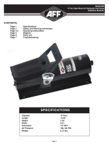
MODEL C
SINGLE-ACTING, SPRING RETURN
HYDRAULIC CYLINDER
Max. Capacity: 55.2 Tons at 10,000 PSI
Parts List
Hydraulic Cylinder
Model 10312

REV0709
Item No. Part No.
No.
Req’d
Description
1
10606
1
Coupler
2
10312-2
2
Spring Retainer
3
10312-3
1
Extension Spring
4
10312-4
1
Transfer Connect
5
10312-5
1
Cylinder Body
6
9575
1
Needle Valve
7
10312-7
1
Square Connect
8
10005
2
Hex. Hd Cap Screw M6*12
9 *10244 2 Lockwasher Φ6
10
35903
1
Handle
11
*12042
2
Copper Washer
12
16110
1
Soc. Hd. Screw 3/8-16*3.5
13
208406
1
Base Plate
14
B1069028
6
machine Screw 3/8-16*1
15
U962127045
1
Front Plate
16
12577
1
Soc. Hd. Screw 3/8-16*3/4
17
*10312-17
1
Wiper
18
10312-18
1
Retainer Nut
19
10312-19
1
Piston
20
*10312-20
1
U-cup Piston Seal
21
*10312-21
1
Seal
*INDICATES PARTS FOUND IN KIT 10312RK

CONTENTS
English ………………………………………………………………………….2-6
Deutsch ………………………………………………………………………...7-11
Français ……………………………………………………………………..12 à 16
Español ……………………………………………………………………….17-21
Italiano ……………………………………………………………………….22-26
Nederlands …………………………………………………………………….27-31
IMPORTANT RECEIVING INSTRUCTIONS
Visually inspect all components for shipping damage. If any shipping damage is
found, notify carrier at once. Shipping damage is NOT covered by warranty. The carrier
is responsible for all repair or replacement cost resulting from damage in shipment.
SAFETY INFORMATION
WARNING
STAY CLEAR OF LOADS SUPPORTED BY HYDRAULICS.
A cylinder, when used as a load lifting device, should never be
used as a load holding device. After the load has been raised,
it should be blocked.
WARNING
DO NOT EXCEED EQUIPMENT RATINGS.
–
–
Never attempt to lift a load weighing more than the capacity
of the cylinder. Overloading causes equipment failure and
possible personal injury.
These cylinders are designed for a maximum pressure o
f
10,000 psi (700 bar). Do not connect these cylinders to a
pump with a higher pressure rating.

WARNING
BE SURE SETUP IS STABLE BEFORE LIFTING LOAD.
– The cylinder should be placed on a flat surface that can support
the load. Where applicable, use a cylinder base for added
stability. Do not weld or otherwise modify the cylinder to
attach a base or other support.
– Avoid situations where loads are not directly centered on the
cylinder plunger. Off-center loads produce considerable
strain on cylinders and plungers. In addition, the load may slip
or fall, causing potentially dangerous results.
– Distribute the load evenly across the entire saddle surface. Tilt
saddles are available to reduce offset loading (except 100
ton models). Always use a saddle to protect the plunger
when threaded attachments are not used.
WARNING
USE ONLY RIGID PIECES TO HOLD LOADS. Carefully
select steel or wood blocks that are capable of supporting the
load. Never use a hydraulic cylinder as a shim or spacer in any
lifting or pressing application.
WARNING
ONLY USE HYDRAULIC CYLINDER IN A
COUPLED SYSTEM.
Never use a cylinder with unconnected couplers. If the cylinder
becomes extremely overloaded, the coupler check ball and/or
hydraulic oil may shoot out of the cylinder causing severe
personal injury.
2

CAUTION
AVOID DAMAGING HYDRAULIC HOSE.
– Avoid sharp bends and kinks when routing hydraulic hoses.
Using a bent or kinked hose will cause severe back-pressure.
Also, sharp bends and kinks will internally damage the hose
leading to premature failure.
– Do not drop heavy objects on hose. A sharp impact may
cause internal damage to hose wire strands. Applying
pressure to a damaged hose may cause it to rupture.
– Do not use the hydraulic hose to carry a hydraulic component
(i.e. pumps, cylinders and valves).
CAUTION
KEEP HYDRAULIC EQUIPMENT AWAY FROM
FLAMES AND HEAT.
Excessive heat will soften packings and seals, resulting in
fluid leaks. Heat also weakens hose materials and packings.
For optimum performance DO NOT expose equipment to
temperatures of 150oF (65oC) or higher. Protect hoses and
cylinders from weld spatter.
3

INSTALLATION
1. Make hydraulic connections. Use a pump with a release
valve or a 3-way valve and one hose for single-acting
cylinders (1). Use a pump with a 4-way valve and two
hoses for double-acting cylinders (2).
IMPORTANT: Double-acting cylinders must have both
couplers connected.
Fully hand-tighten all couplers. Loose coupler connections will block the flow of
oil between the pump and the cylinder.
2. Remove air from the cylinder as shown below.
Single-acting cylinders: Position the cylinder so that the plunger is pointed down and
the cylinder lower than the pump. Fully extend and retract the cylinder 2 or 3 times.
Double-acting cylinders: Lay the cylinder on its side and have the couplers
facing up. Fully extend and retract the cylinder 2 or 3 times.
NOTE: Collar threads are rated for the full capacity of the cylinder when fully
engaged in attachments.
NOTE: The use of cylinder attachments or extensions reduces the cylinder capacity by
at least 50%.
4

OPERATION
WARNING
DO NOT HANDLE PRESSURIZED HOSES. Escaping oil
under pressure can penetrate the skin,
causing serious injury. If oil is injected under the skin, see a
doctor immediately.
Operate the hydraulic pump to advance and retract the cylinder.
Some single-acting cylinders are spring-return, others are load return. The speed of
retraction is affected by the length of the hose and other restrictions in the line. Double-
acting cylinders are powered in both directions by the pump.
The cylinder stop ring is designed to take the full load. However, to reduce cylinder
wear, use less than full stroke when possible.
MAINTENANCE
1. Use dust caps when cylinders are disconnected from the hose. Keep entire
cylinder clean to prolong cylinder life.
2. Store cylinders up-right to prevent seal distortion.
5

TROUBLE SHOOTING
These cylinders should be repaired only by Authorized ESCO Technical Service
Centers. Single-acting cylinders are spring loaded and require special disassembly
techniques to prevent personal injury.
PROBLEM POSSIBLE CAUSES
Pump release valve open.
Coupler not fully tightened.
Oil level in pump is low.
Pump malfunctioning.
Cylinder will not advance.
Load is too heavy for cylinder.
Oil level in pump is low.
Coupler not fully tightened.
Cylinder advances part way.
Cylinder plunger binding.
Air in hydraulic system. Cylinder advances in spurts.
Cylinder plunger binding.
Leaking connection.
Coupler not fully tightened.
Cylinder advances slower than normal.
Pump malfunctioning.
Cylinder seals leaking.
Pump malfunctioning.
Leaking connection.
Cylinder advances but will not hold.
Incorrect system set-up.
Worn or damaged seals.
Internal cylinder damage.
Cylinder leaks oil.
Loose connection.
Pump release valve is closed.
Coupler not fully tightened.
Pump reservoir over-filled.
Narrow hose restricting flow.
Broken or weak retraction spring.
Cylinder will not retract or retracts slower than normal.
Cylinder damaged internally.
Coupler not fully tightened. Oil leaking from external relief valve.
Restriction in return line.
6
/